
Subscribe to Our Youtube Channel
Related Manuals for Vecow SPC-5000


Summary of Contents for Vecow SPC-5000
- Page 1 USER USER SPC-5000 Manual Manual Intel® Core™ i7/i5/i3 SoC (Whiskey Lake) Ultra-Compact Fanless Embedded System, 2 GigE LAN, 4 10G USB 3.1 Gen 2, 2 COM, 9V to 48V, Ignition Control, -40°C to 85°C 1.0.0 Edition 20191212...
- Page 2 Record of Revision Version Date Remark Page Description 0.10 2019/12/05 Preliminary Release 1.00 2019/12/12 Official Release ©Vecow SPC-5000 User Manual...
- Page 3 This manual is released by Vecow Co., Ltd. for reference purpose only. All product offerings and specifications are subject to change without prior notice. It does not represent commitment of Vecow Co., Ltd. Vecow shall not be liable for direct, indirect, special, incidental, or consequential damages arising out of the use of the product or documentation or any infringements upon the rights of third parties, which may result from such use.
- Page 4 4 USB 3.0 Gen2, 4 COM, 1 SIM, 2 PoE LAN, 16 Isolated DIO ® ® SPC-5200, onboard Intel Celeron 4305UE, 4 GigE LAN, 1 SSD, SPC-5200-4305U 4 USB 3.0 Gen2, 4 COM, 1 SIM, 2 PoE LAN, 16 Isolated DIO ©Vecow SPC-5000 User Manual...
- Page 5 DIN-Rail Mounting VESA Mount VESA Mounting Kit for SPC-5200 DIN-RAIL DIN Rail and VESA Mounting Kit for SPC-5200 DIN-RAIL DIN Rail Kit for SPC-5000/5100 4G Module Mini PCIe 4G/GPS Module with Antenna WiFi & Bluetooth ® Intel Mini PCIe WiFi & Bluetooth Module with Antenna Module ©Vecow SPC-5000 User Manual...
-
Page 6: Table Of Contents
1.5 Mechanical Dimension 1.5.1 SPC-5000 Mechanical Drawing 1.5.2 SPC-5100 Mechanical Drawing 1.5.3 SPC-5200 Mechanical Drawing CHAPTER 2 GETTING TO KNOW YOUR SPC-5000 2.1 Packing List 2.2 Front Panel I/O & Functions 2.3 Rear Panel I/O & Functions 2.4 Connector/Jumper Locations 2.5 Main Board Jumper Settings... - Page 7 4.6 Boot Functions 4.7 Save & Exit APPENDIX A : Isolated DIO Guide APPENDIX B : Software Functions APPENDIX C : RAID Functions APPENDIX D : Power Consumption APPENDIX E : Supported Memory & Storage List ©Vecow SPC-5000 User Manual...
-
Page 8: Chapter 1 General Introduction
GENERAL INTRODUCTION 1.1 Overview SPC-5000 is a series of rugged Ultra-compact Fanless Embedded Box PC. ® Powered by Quad-core 8th generation Intel Core™ i7/i5/i3 U-series processor (Whiskey Lake), dual channel DDR4 2133MHz up to 32GB memory; Advanced ® Intel HD Graphics 620 graphics engine supports DirectX 12 and OpenGL 4.5 API, DVI-D and DisplayPort dual display serving up to ultra HD 4K resolution;... -
Page 9: Features
• Compact size, matches 1U one rack unit of height • DisplayPort and DVI-D dual display supports up to 4K display • 2 Independent GigE LAN, iAMT 12.0 supported (SPC-5000/5100) • 4 Independent GigE LAN with 2 PoE (Power over Ethernet), iAMT 12.0 supported (SPC-5200) •... -
Page 10: Product Specification
1.3 Product Specification 1.3.1 Specifications of SPC-5000 System ® Quad Core Intel Core™ i7/i5/i3 U-series Processor Processor (Whiskey Lake) ® Chipset Intel SoC (Cannon Lake) BIOS IT8786E Memory 1 DDR4 2400MHz SO-DIMM, up to 32GB Graphics ® Graphics Processor Intel UHD Graphics 620 •... - Page 11 5% to 95% Humidity, non-condensing Relative Humidity 95% at 70°C • IEC 60068-2-27 Shock • SSD : 50G @wallmount, Half-sine, 11ms • IEC 60068-2-64 Vibration • SSD : 5Grms, 5Hz to 500Hz, 3 Axis CE, FCC, EN50155, EN50121-3-2 ©Vecow SPC-5000 User Manual GENERAL INTRODUCTION...
-
Page 12: Specifications Of Spc-5100
• 1 SUMIT Connector B (Internal, optional) Power Power Input 9V to 48V DC-in Power Interface 3-pin Terminal Block : V+, V-, Frame Ground Ignition Control 16 Mode (Internal) Remote Switch 3-pin Terminal Block : On, Off, IGN ©Vecow SPC-5000 User Manual GENERAL INTRODUCTION... - Page 13 5% to 95% Humidity, non-condensing Relative Humidity 95% at 85°C • IEC 60068-2-27 Shock • SSD : 50G @wallmount, Half-sine, 11ms • IEC 60068-2-64 Vibration • SSD : 5Grms, 5Hz to 500Hz, 3 Axis CE, FCC, EN50155, EN50121-3-2 ©Vecow SPC-5000 User Manual GENERAL INTRODUCTION...
-
Page 14: Specifications Of Spc-5200
16 Isolated DIO : 8 DI, 8 DO Power, HDD, PoE SIM Card 1 SIM Card Socket (Internal) Expansion 2 Mini PCIe Socket : Mini PCIe • 1 Full-Size for PCIe/USB/Internal SIM Card • 1 Full-size for PCIe/USB/Optional mSATA ©Vecow SPC-5000 User Manual GENERAL INTRODUCTION... - Page 15 5% to 95% Humidity, non-condensing Relative Humidity 95% at 70°C • IEC 60068-2-27 Shock • SSD : 50G @wallmount, Half-sine, 11ms • IEC 60068-2-64 Vibration • SSD : 5Grms, 5Hz to 500Hz, 3 Axis CE, FCC, EN50155, EN50121-3-2 ©Vecow SPC-5000 User Manual GENERAL INTRODUCTION...
-
Page 16: Supported Cpu List
Cores Cache Max. Frequency ECC Memory ® Intel Core™ i7-8665UE Up to 4.4GHz ® Intel Core™ i5-8365UE Up to 4.1GHz ® Intel Core™ i3-8145UE Up to 3.9GHz ® Intel Celeron 4305UE Up to 2.0GHz ©Vecow SPC-5000 User Manual GENERAL INTRODUCTION... -
Page 17: Mechanical Dimension
1.5 Mechanical Dimension 1.5.1 SPC-5000 Mechanical Drawing Unit : mm (inch) 185.4 (7.30”) 169.1 (6.66”) 150.4 (5.92”) 1.5.2 SPC-5100 Mechanical Drawing 185.4 (7.30”) Unit : mm (inch) 169.1 (6.66”) 150.4 (5.92”) 1.5.3 SPC-5200 Mechanical Drawing 262.4 (10.33) Unit : mm (inch) 246.1 (9.69) -
Page 18: Chapter 2 Getting To Know Your Spc-5000
GETTING TO KNOW YOUR SPC-5000 2.1 Packing List 2.1.1 SPC-5000 & SPC-5100 Packing List Item Description SPC-5000/5100/Embedded System Driver/User Manual DVD • Wall-mounting bracket (SET) • Terminal block plug pitch 5.0mm 3-pin • Foot Pad Item Description Outlook Usage PHILLPIS... - Page 19 • Terminal block plug pitch 5.0mm 3-pin • Foot Pad Item Description Outlook Usage PHILLPIS M4x16L with Mount 53-24D6416-30B washer, Ni PHILLPIS Mini PCIe 53-2426906-30B M2.5x6L, Ni slot PHILLPIS Mount 53-2426206-80B M3*6L M3x4L SSD/HDD 53-2470000-218 ©Vecow SPC-5000 User Manual GETTING TO KNOW YOUR SPC-5000...
-
Page 20: Front Panel I/O & Functions
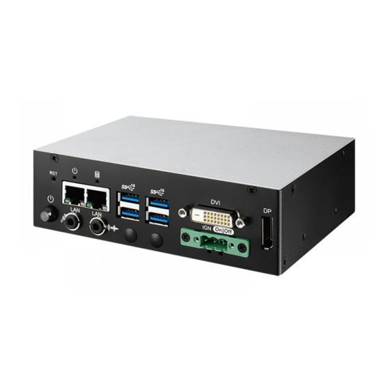
2.2 Front Panel I/O & Functions 2.2.1 SPC-5000/5100 Front I/O & Functions In Vecow's SPC-5000/5100 series family, all I/O connectors are located on the front panel. Most of the general connections to the computer device, such as audio, USB3.1, DVI-D, LAN Jack, and DisplayPort, are placed on the front panel. - Page 21 You will need a DVI-D cable when connecting to a display device. 2.2.1.5 DisplayPort On | Off DisplayPort connection supports up to 4096 x 2304 resolution at 60Hz. ©Vecow SPC-5000 User Manual GETTING TO KNOW YOUR SPC-5000...
- Page 22 On | Off There are 4 USB 3.1 connections available supporting up to 10GB per second data rate in the front side of SPC-5000/5100. It also compliant with the requirements of Super Speed (SS), high speed (HS), full speed (FS) and low speed (LS).
- Page 23 Ignition (IGN) 2.2.2 SPC-5200 Front I/O & Functions In Vecow's SPC-5200 series family, all I/O connectors are located on the front panel. Most of the general connections to the computer device, such as audio, USB3.1, DVI-D, LAN Jack, and DisplayPort, are placed on the front panel.
- Page 24 The DVI output mode supports up to 1920 x 1080 resolution. The DVI is automatically selected according to the display device connected. You will need a DVI-D cable when connecting to a display device. ©Vecow SPC-5000 User Manual GETTING TO KNOW YOUR SPC-5000...
- Page 25 5200. Onboard Realtek ALC892 audio codec supports 5.1 channel HD audio ® and fully complies with Intel High Definition Audio (Azalia) specifications. To utilize the audio function in Windows platform, you need to install corresponding drivers for Realtek ALC892 codec. ©Vecow SPC-5000 User Manual GETTING TO KNOW YOUR SPC-5000...
- Page 26 Another function is provided ignition power control feature for in-vehicle applications. The built-in MCU monitors the ignition signal and turns on/off the system according to pre-defined on/off delay period. Pin No. Definition 1 2 3 Ignition (IGN) ©Vecow SPC-5000 User Manual GETTING TO KNOW YOUR SPC-5000...
- Page 27 DIO_GND DIO_GND External 6V to 36V DC Input GPI SINK Mode Isolated GPI input circuit in SINK mode (NPN) is illustrated as follow : Power Supply +24V Internal Circuit SINK IN_0 ©Vecow SPC-5000 User Manual GETTING TO KNOW YOUR SPC-5000...
- Page 28 Only when PoE port starts to supply power to power devices, the dedicated LED will be lightened. POE LED LED Color POE Status POE_LED1/POE_LED2 Solid Orange POE ON ©Vecow SPC-5000 User Manual GETTING TO KNOW YOUR SPC-5000...
-
Page 29: Rear Panel I/O & Functions
2.3 Rear Panel I/O & Functions 2.3.1 SPC-5000/5100 Rear I/O & Functions 2.3.1.1 Power Terminal Block DC-IN 9V-48V SPC-5000/5100 supports 9V to 48V DC power input. Pin No. Definition 1 2 3 Earth GND 2.3.1.2 Serial Port COM DC-IN 9V-48V Serial port can be configured for RS-232, RS-422, or RS-485 with auto flow control communication. - Page 30 Definition 1 2 3 Earth GND 2.3.2.2 Serial Port COM BIOS Setting Function RS-232 COM 1 RS-422 (5-wire) COM 2 RS-422 (9-wire) COM 3 COM 4 RS-485 RS-485 w/z auto-flow control ©Vecow SPC-5000 User Manual GETTING TO KNOW YOUR SPC-5000...
-
Page 31: Connector/Jumper Locations
2.4 Connector/Jumper Locations 2.4.1 SPC-5000/5100/5200 Main Board Pin Header JSTATUS JP10 CON1 JHDD SYS_FAN1 JP11 JCOM1 JRESET JPWBTN JCOM2 JCOM3 JCOM4 JDIO2 DIMM1 JDIO1 SUMIT_B J80P JUSB2 JUSB1 SUMIT_A CN13 JSEL_DIO JPS2 CN14 CN15 CN11 CN16 ©Vecow SPC-5000 User Manual... - Page 32 Panasonic BR2032 190mAh lithium battery. It is recommended that you not replace the lithium battery on your own, but if the battery needs to be changed, please contact the Vecow RMA service team. ©Vecow SPC-5000 User Manual GETTING TO KNOW YOUR SPC-5000...
- Page 33 Chapter 4 for more details of driver installation. The pinouts of Audio port are listed in the following table : Pin No. Definition Pin No. Definition A_z_MIC1-L GND_A A_z_MIC1-R GND_EARTH A_z_LINEO-R A_z_LINEI-R F_IO_SENSE GND_EARTH A_z_LINEO-L A_z_LINEI-L ©Vecow SPC-5000 User Manual GETTING TO KNOW YOUR SPC-5000...
- Page 34 The pin assignments of JUSB1 and JUSB2 are listed in the following table : Pin No. Definition Pin No. Definition JUSB1 USB_VCC USB_VCC USB_VCC USB_D_4N USB_D_4P USB_D_5N USB_D_5P Pin No. Definition Pin No. Definition JUSB2 USB_VCC USB_VCC USB_VCC USB_D_6N USB_D_6P USB_D_7N USB_D_7P ©Vecow SPC-5000 User Manual GETTING TO KNOW YOUR SPC-5000...
- Page 35 Reserved +3.3Vaux USB_D+ USB_D- PETp0 PETn0 SMB_DATA SMB_CLK +1.5V PERp0 PERn0 +3.3Vaux PERST# Reserved reserved Reserved Mechanical Key Reserved REFCLK+ Reserved REFCLK- Reserved Reserved CLKREQ# Reserved Reserved 1.5V Reserved WAKE# 3.3Vaux ©Vecow SPC-5000 User Manual GETTING TO KNOW YOUR SPC-5000...
- Page 36 Reserved +3.3Vaux USB_D+ USB_D- PETp0 PETn0 SMB_DATA SMB_CLK +1.5V PERp0 PERn0 +3.3Vaux PERST# Reserved reserved Reserved Mechanical Key UIM_VPP REFCLK+ UIM_RESET REFCLK- UIM_CLK UIM_DATA CLKREQ# UIM_PWR Reserved 1.5V Reserved WAKE# 3.3Vaux ©Vecow SPC-5000 User Manual GETTING TO KNOW YOUR SPC-5000...
- Page 37 GND_EARTH GND_EARTH GND_EARTH GND_EARTH ----------- CTS- RXD- RXD- ----------- ----------- CTS+ ----------- 1, 2 3, 4 RXD+ RXD+ ----------- ----------- RTS+ ----------- TXD+ TXD+ DATA+ ----------- RTS- ----------- TXD- TXD- DATA- ©Vecow SPC-5000 User Manual GETTING TO KNOW YOUR SPC-5000...
- Page 38 There are 4 USB 3.1 Gen2 connections available supporting up to 10GB per second data rate in the top side of EMBC-3000. They are also compliant with the requirements of SuperSpeed (SS), high speed (HS), full speed (FS) and low speed (LS). ©Vecow SPC-5000 User Manual GETTING TO KNOW YOUR SPC-5000...
- Page 39 1000Mbps Ethernet network; The left LED will keep twinkling/off when Ethernet data packets are being transmitted/received. LED Location LED Color 10Mbps 100Mbps 1000Mbps Green/ Solid Solid Right Orange Green Orange Twinkling Twinkling Twinkling Left Green Green Green Green ©Vecow SPC-5000 User Manual GETTING TO KNOW YOUR SPC-5000...
- Page 40 The LCD inverter is connected to J3 via a JST 7-pin, 2.5mm connector providing +5V/+12V power to LCD display. The pin assignments are listed in the following table : Pin No. Definition Pin No. Definition +12V +12V LBKLT_CTL LBKLT_EN ©Vecow SPC-5000 User Manual GETTING TO KNOW YOUR SPC-5000...
- Page 41 EMBC-3000 supports single Display Port and up to 4096 x 2304 pixels resolution. CN11 2.4.1.13 CN1 : DC Power input EMBC-3000 supports 9V to 48V DC power input by wire-to-board connector in the top side. Pin No. Definition Pin No. Definition ©Vecow SPC-5000 User Manual GETTING TO KNOW YOUR SPC-5000...
- Page 42 5V (Up to 2A) and 12V (Up to 2A) currents to the hard drive or SSD. The pinassignments of J1 is listed in the following table : Pin No. Definition Pin No. Definition +12V ©Vecow SPC-5000 User Manual GETTING TO KNOW YOUR SPC-5000...
- Page 43 Reserved Reserved Reserved Reserved USB_3+ Reserved USB_3- Reserved Reserved USB_2+ LPC_AD0 USB_2- LPC_AD1 LPC_AD2 USB_1+ LPC_AD3 USB_1- LPC_FRAME# SERIRQ# USB_0+ Reserved USB_0- CLK_33MHz A_PET_P0 A_PER_P0 A_PET_N0 A_PER_N0 PERST# A_CLKP WAKE# A_CLKN ©Vecow SPC-5000 User Manual GETTING TO KNOW YOUR SPC-5000...
- Page 44 B_PER_N0 C_CLKP B_CLKP C_CLKN B_CLKN CPRSNT#/C_PE_CLKREQ# C_PET_P0 C_PER_P0 C_PET_N0 C_PER_N0 C_PET_P1 C_PER_P1 C_PET_N1 C_PER_N1 C_PET_P2 C_PER_P2 C_PET_N2 C_PER_N2 C_PET_P3 C_PER_P3 C_PET_N3 C_PER_N3 PERST# WAKE# Reserves Reserves Reserves +3.3V +3.3V +3.3V +5V_AUX ©Vecow SPC-5000 User Manual GETTING TO KNOW YOUR SPC-5000...
- Page 45 Fan PWM 2.4.1.18 JPS2 : PS/2 Keyboard and Mouse JPS2 JPS2 Keyboard and mouse pin assignment as the following table : Pin No. Definition Pin No. Definition SIO_MCLK SIO_MDAT SIO_KCLK SIO_KDAT VCC5_KBMS ©Vecow SPC-5000 User Manual GETTING TO KNOW YOUR SPC-5000...
- Page 46 SIO_GPO76 SIO_GPI87 SIO_GPO77 +VDIO +VDIO 2.4.1.20 JP11 : IGNITION Control and Remote Power on switch JP11 Pin assignment as the following table : Pin No. Definition Pin No. Definition FP_PWR_BTN_P IGNITION ©Vecow SPC-5000 User Manual GETTING TO KNOW YOUR SPC-5000...
- Page 47 2.4.2 SPC-5000/5100/5200 PCB Bottom Side CPU1 U10 (I219-LM) U11 (I210-IT) HDD_LED PWR_LED Green-PWR_LED : If the LED is solid green, it indicates that the system is powered on. Yellow-HDD_LED : A hard disk LED. If the LED is on, it indicates that the system's storage is functional.
-
Page 48: Main Board Jumper Settings
To "open" a jumper, you remove the clip. Sometimes a jumper will have three pins, labeled 1, 2, and 3. In this case you would connect either pins 1 and 2, or 2 and 3. Open Closed Closed 2-3 ©Vecow SPC-5000 User Manual GETTING TO KNOW YOUR SPC-5000... - Page 49 LVDS power input; closing Pin 2 and Pin 3 is for 5V LVDS power input. Pin No. Definition +3.3V (Default) 2.5.3 JP2 : Clear CMOS, JP10 : Clear ME JP2 JP10 Pin No. Definition Normal Clear CMOS Pin No. Definition JP10 Normal Clear ME ©Vecow SPC-5000 User Manual GETTING TO KNOW YOUR SPC-5000...
- Page 50 2.5.4 JP5 : Power Selection for EXT and INT USB 3.1 Gen2/USB 2.0 Ports Pin No. Power +5V Standby Power +5V System Power 2.5.5 JP9 : Backlight Control Level Selection Pin No. Power 3.3V ©Vecow SPC-5000 User Manual GETTING TO KNOW YOUR SPC-5000...
-
Page 51: Ignition Control
2.6.1 Adjust Ignition Control Modes EMBC-3000 series provides 16 modes of different power on/off delay periods adjustable via SW3 switch. The default rotary switch is set to 0 in ATX/AT power mode. ©Vecow SPC-5000 User Manual GETTING TO KNOW YOUR SPC-5000... - Page 52 5 seconds 30 minutes 5 seconds 1 hour 10 seconds 2 hours 10 seconds 4 hours 10 seconds 6 hours 10 seconds 8 hours 10 seconds 12 hours 10 seconds 24 hours ©Vecow SPC-5000 User Manual GETTING TO KNOW YOUR SPC-5000...
- Page 53 3. For proper ignition control, the power button setting should be "Power Down" mode. In Windows for example, you need to set "When I press the power button" to Shut down. ©Vecow SPC-5000 User Manual GETTING TO KNOW YOUR SPC-5000...
-
Page 54: Chapter 3 System Setup
SYSTEM SETUP 3.1 How to Open Your SPC-5000 3.1.1 SPC-5000 or SPC-5100 Step 1 Remove one F-M3x4 screw. Step 2 Remove two F-M3x4 screw. Step 3 Remove one F-M3x4 screw. ©Vecow SPC-5000 User Manual SYSTEM SETUP... - Page 55 Step 4 Remove one F-M3x4 screw. Step 5 Open bottom Cover. ©Vecow SPC-5000 User Manual SYSTEM SETUP...
- Page 56 3.1.2 SPC-5200 Step 1 Remove eight F-M3x4 screw. Step 2 Open bottom Cover. ©Vecow SPC-5000 User Manual SYSTEM SETUP...
-
Page 57: Installing Ddr4 So-Dimm Module
3.2 Installing DDR4 SO-DIMM Module Step 1 Install DDR4 RAM module Step 2 Install DDR4 RAM module into SO-DIMM slot. into SO-DIMM slot. ©Vecow SPC-5000 User Manual SYSTEM SETUP... -
Page 58: Installing Mini Pcie Card
3.3 Installing Mini PCIe Card Step 1 Install Mini PCIe card into Step 2 Fasten one M2.5 screw. the Mini PCIe slot. ©Vecow SPC-5000 User Manual SYSTEM SETUP... -
Page 59: Installing Antenna Cable
3.4 Installing Antenna Cable Step 1 Check antenna cable and washers. Step 2 Install antenna cable and then fasten washer and nut. ©Vecow SPC-5000 User Manual SYSTEM SETUP... -
Page 60: Installing Sim Card
3.5 Installing SIM Card Step 1 Open the SIM card cover. Step 2 Install SIM card into to the SIM card slot and then close the SIM card cover. ©Vecow SPC-5000 User Manual SYSTEM SETUP... -
Page 61: Installing Ssd/Hdd
3.6 Installing SSD/HDD 3.6.1 Installing SPC-5000 or SPC-5100 SSD/HDD Step 1 Fasten 4 M3 screw. ©Vecow SPC-5000 User Manual SYSTEM SETUP... - Page 62 3.6.2 Installing SPC-5200 SSD/HDD Step 1 Fasten 4 M3 screw. ©Vecow SPC-5000 User Manual SYSTEM SETUP...
-
Page 63: Mounting Your Spc-5000
3.7 Mounting Your SPC-5000 3.8.1 SPC-5000 Fasten four M3 screws. (53-2426206-80B) 3.8.2 SPC-5100 Fasten four M3 screws. (53-2426206-80B) ©Vecow SPC-5000 User Manual SYSTEM SETUP... - Page 64 3.8.3 SPC-5200 Fasten four M3 screws. (53-2426206-80B) ©Vecow SPC-5000 User Manual SYSTEM SETUP...
-
Page 65: Chapter 4 Bios Setup
BIOS provide an interface for user to check and change system configuration. The BIOS setup program is accessed by pressing the <Del> key when POST display output then main BIOS Setup menu screen is displayed. ©Vecow SPC-5000 User Manual BIOS SETUP... -
Page 66: Main Manu
Set the Time. Use Tab to switch between Time elements. 4.3 Advanced Functions Figure 4-3 : BIOS Advanced Menu Select Advanced tab to enter advanced BIOS Setup options such as CPU Configuration, SATA Configuration and USB Configuration. ©Vecow SPC-5000 User Manual BIOS SETUP... - Page 67 Enabled or Disabled Hyper-Threading Technology. Enable/Disable AES (Advanced Encryption Standard). Intel Trusted Execution Technology Enables utilization of additional hardware capabilities provided by Intel Trusted Execution Technology. Changed require a full power cycle to take effect. ©Vecow SPC-5000 User Manual BIOS SETUP...
- Page 68 Deactivate option will set MSR to Nominal and MMIO to Zero. Configurable TDP allows operation in situation where extra cooling is available or situations where a cooler and quieter mode of operation is desired. ©Vecow SPC-5000 User Manual BIOS SETUP...
- Page 69 MEBx Setup. Note : This option does not disable Manageability Features in FW. AMT Configuration Configure Intel Active Management Technology Parameters. ME Unconfig on RTC Clear Disabling this option will cause ME not be unconfigured on RTC clear. ©Vecow SPC-5000 User Manual BIOS SETUP...
- Page 70 Select the highest ACPI sleep state the system will enter when the SUSPEND button is pressed. S3 Video Repost Enable or Disable S3 Video Repost. 4.3.6 SMART Settings Figure 4-3-6 : SMART Settings SMART Self Test Run SMART Self-test on all HDDs during POST. ©Vecow SPC-5000 User Manual BIOS SETUP...
- Page 71 Set Parameters of Serial Port 1 (COM1). Serial Port 2 Configuration Set Parameters of Serial Port 2 (COM2). Serial Port 3 Configuration Set Parameters of Serial Port 3 (COM3). Serial Port 4 Configuration Set Parameters of Serial Port 4 (COM4). ©Vecow SPC-5000 User Manual BIOS SETUP...
- Page 72 Temperature Limit value of Fan Start (Degree C). (Range : 10-80) PWM Start Value (%) Default PWM Value of Fan. (Range : 15%-100%) Full Speed Temperature Temperature Limit value of Fan Full Speed (Degree C). (Range : 50-90) ©Vecow SPC-5000 User Manual BIOS SETUP...
- Page 73 Legacy Console Redirection Settings Legacy Console Redirection Settings Serial Port for Out-of-Band management/Windows Emergency Management Services (EMS) Console Redirection Enable or Disable. 4.3.10 Intel TXT Information Figure 4-3-10 : Intel TXT Information Display Intel TXT information. ©Vecow SPC-5000 User Manual BIOS SETUP...
- Page 74 4.3.12 PCI Subsystem Settings Figure 4-3-12 : PCI Subsystem Settings Above 4G Decoding Globally Enables or Disables 64bit capable Devices to be Decoded in Above 4G Address Space (Only if System Supports 64 bit PCI Decoding). ©Vecow SPC-5000 User Manual BIOS SETUP...
- Page 75 Maximum time the device will take before it properly reports itself to the Host Controller. 'Auto' uses default value : for a Root port it is 100 ms, for a Hub port the delay is taken from Hub descriptor. ©Vecow SPC-5000 User Manual BIOS SETUP...
- Page 76 Controls the execution of UEFI and Legacy Storage OpROM. Video Controls the execution of UEFI and Legacy Video OpROM. Other PCI devices Determines OpROM execution policy for devices other than Network, Storage, or Video. ©Vecow SPC-5000 User Manual BIOS SETUP...
- Page 77 Support to Enable/disable IPSEC certificate for lkev. PXE boot wait time Wait time to press ESC key to abort the PXE boot. Media detect count Number of times presence of media will be checked. ©Vecow SPC-5000 User Manual BIOS SETUP...
-
Page 78: Chipset Functions
VT-d capability. Above 4GB MMIO BIOS assignment Enable/Disable above 4GB MemoryMappedIO BIOS assignment. This is disabled automatically when Aperture Size is set to 2048MB. 4.4.1.1 Memory Configuration Figure 4-4-1-1 : Memory Information Display memory information. ©Vecow SPC-5000 User Manual BIOS SETUP... - Page 79 ME is on at Sx state.). Serial IRQ Mode Configure Serial IRQ Mode. State After G3 Specify what state to go to when power is re-applied after a power failure (G3 state). ©Vecow SPC-5000 User Manual BIOS SETUP...
- Page 80 The control of Active State Power Management of the DMI Link. Native PCIE Enable PCI Express Native Support Enable/Disable. This feature is available in vista and beyond Windows OS. PCI Express device settings BIOS options for PCI Express device setting. ©Vecow SPC-5000 User Manual BIOS SETUP...
- Page 81 On an edge detect from 0 to 1, the PCH starts a COMRESET initialization sequence to the device. SATA Device Type Identify the SATA port is connected to Solid State Drive or Hard Disk Drive. ©Vecow SPC-5000 User Manual BIOS SETUP...
- Page 82 Enable/Disable the PCH BIOS Lock Enable (BLE bit) feature. 4.4.3 LVDS Configuration Figure 4-4-3 : LVDS Panel Settings The LVDS Configuration option will be present if LVDS panel is connected on system. LCD Panel Type Select LCD Panel Resolution. ©Vecow SPC-5000 User Manual BIOS SETUP...
-
Page 83: Security
4.5 Security Figure 4-5 : BIOS Security Menu Administrator Password Set administrator password. User Password Set user password. Secure Boot Secure Boot coonfiguration. ©Vecow SPC-5000 User Manual BIOS SETUP... - Page 84 Secure Boot mode options : Standard or Custom. In Custom mode, Secure Boot Policy variables can be configured by a physically present user without full authentication. Key Management Enables expert users to modify Secure Boot Policy variables without full authentication. ©Vecow SPC-5000 User Manual BIOS SETUP...
-
Page 85: Boot Functions
Select the keyboard NumLock state. Quiet Boot Enables or disables Quiet Boot option. Boot Option #x Sets the system boot order. Hard Drive BBS Priorities Set the order of the legacy devices in this group. ©Vecow SPC-5000 User Manual BIOS SETUP... -
Page 86: Save & Exit
Restore Defaults Restore/Load Default values for all the setup options. Save as User Defaults Save the changes done so far as User Defaults. Restore User Defaults Restore the User Defaults to all the setup options. ©Vecow SPC-5000 User Manual BIOS SETUP... -
Page 87: Appendix A : Isolated Dio Guide
APPENDIX A : Isolated DIO Guide A.1 Function Description The SPC-5000 offers a 16-bit DIO (Isolated/Non-Isolated) 20-pin terminal block connector, and a watchdog timer. DIO definition is shown below : Non-Isolated DIO Non-Isolated DIO Pin No. Pin No. JDIO2 Definition... - Page 88 DIO Connector (NPN, Default) DIO_VDC (Pin 20) 6-48V DC DO (Pin 11-18) DIO_GND (Pin 10, 19) Source Mode Device DIO Connector (PNP) DIO_VDC (Pin 20) 6-48V DC DO (Pin 11-18) DIO_GND (Pin 10, 19) ©Vecow SPC-5000 User Manual Appendix A...
- Page 89 Sample folder include sample program, driver library, and API library. Source folder include sample program source code that compile on Visual Studio 2008. A.4 Sample Sample folder include x32 and x64 versions, as shown below : Sample SPC5K.exe, as shown below : ©Vecow SPC-5000 User Manual Appendix A...
- Page 90 DIO1 group : Isolate check button : DIO type of DIO configuration, isolated/non-isolated, defined in SPC-5000 series user manual. Read button : Set DIO configuration to get DI/DIO input state. DO type check button : User setting, DO type of DIO configuration to setup 8 pins - Source/Sink.
- Page 91 WDT counting by program timer after set WDT. Shown after Write button action. WDT setup day format texts (user setting) : User setting, WDT value, format : day'hour'minute'second. WDT counting day format text (read only) : WDT counting, format : day'hour'minute'second. ©Vecow SPC-5000 User Manual Appendix A...
-
Page 92: Appendix B : Software Functions
Mask ([15:0]) : In/Out, pin setting by hexadecimal bitmask 1 : Output; 0 : Input Return : TRUE (1) : Success; FALSE (0) : Fail (Initial error, or call by pointer error, or hardware problem) ©Vecow SPC-5000 User Manual Appendix B... - Page 93 Set isolated DIO output (DO) DO ([7:0]) : Output state, pin setting by hexadecimal bitmask 1 : High; 0 : Low Return : TRUE (1) : Success; FALSE (0) : Fail (Initial error, or hardware problem) ©Vecow SPC-5000 User Manual Appendix B...
- Page 94 FALSE (0) : Fail (Initial error, or setup 0 error, or hardware problem) BOOL CancelWDT () Cancel watchdog timer Return : TRUE (1) : Success; FALSE (0) : Fail (Initial error, or hardware problem) ©Vecow SPC-5000 User Manual Appendix B...
-
Page 95: Appendix C : Raid Functions
C.3 To Install All Device Drivers of the System The instructions are as follows : 1. To install Chipset driver 2. To install VGA driver 3. To install ME driver (if available) 4. To install Network driver 5. To install Audio driver ©Vecow SPC-5000 User Manual Appendix C... - Page 96 C.6 To Create RAID Volume on "Rapid Storage Technology" Software The system is featured with three SATA HDD's for RAID volume, so there are two options to choose on this page. Let's take RAID 1 as an example, select "RAID 1". ©Vecow SPC-5000 User Manual Appendix C...
- Page 97 Then add "Logical Device" for Windows access. C.8 If One SATA HDD on RAID Volume is Out-of-use After RAID 1 volume created, you can see the figure of SATA device allocation. HDD CAUTION Sign ©Vecow SPC-5000 User Manual Appendix C...
- Page 98 There is a warning will pop-up to ask you if the disk is not a member of original RAID volume. If you press "Rebuild", it will replace the broken SATA HDD to the last one SATA HDD of RAID volume. ©Vecow SPC-5000 User Manual Appendix C...
-
Page 99: Appendix D : Power Consumption
Innodisk 3MG2-P DGS25-64GD81BC1QC 64GB SATA 1 Transcend SSD370 TS64GSSD370 64GB mPCIe 1 UMX-100 mPCIe 2 UMX-100 SUNON PF40281B1-Q000-S99 LAN1 (i219) 1.0Gbps LAN2 (i210) 1.0Gbps Graphics Output Power Plan Balance (Windows10 Power plan) Power Source Chroma 62006P-100-25 ©Vecow SPC-5000 User Manual Appendix D... - Page 100 Run 100% CPU Power usage with 2D usage with 3D Input Current Consumption Current Consumption 2.240A 20.16W 4.270A 38.43W 1.678A 20.13W 3.300A 39.60W Core™ i7- 8665UE 0.836A 20.07W 1.645A 39.48W 0.455A 21.85W 0.847A 40.64W ©Vecow SPC-5000 User Manual Appendix D...
- Page 101 Run 100% CPU Power usage with 2D usage with 3D Input Current Consumption Current Consumption 2.137A 19.23W 3.744A 33.70W 1.646A 19.76W 2.832A 33.99W Core™ i5- 8365UE 0.802A 19.24W 1.395A 33.49W 0.436A 20.93W 0.725A 34.81W ©Vecow SPC-5000 User Manual Appendix D...
- Page 102 Run 100% CPU Power usage with 2D usage with 3D Input Current Consumption Current Consumption 2.040A 18.36W 3.601A 32.41W 1.578A 18.93W 2.666A 31.99W Core™ i3- 8145UE 0.787A 18.88W 1.348A 32.35W 0.414A 19.86W 0.698A 33.49W ©Vecow SPC-5000 User Manual Appendix D...
- Page 103 Innodisk 3MG2-P DGS25-64GD81BC1QC 64GB SATA 1 Transcend SSD370 TS64GSSD370 64GB mPCIe 1 PMX-100 mPCIe 2 UMX-100 DMX-100-E SUNON PF40281B1-Q000-S99 LAN1 (i219) 1.0Gbps LAN2 (i210) 1.0Gbps Graphics Output Power Plan Balance (Windows10 Power plan) Power Source Chroma 62006P-100-25 ©Vecow SPC-5000 User Manual Appendix D...
- Page 104 Run 100% CPU Power usage with 2D usage with 3D Input Current Consumption Current Consumption 2.440A 21.96W 4.471A 40.24W 1.838A 22.06W 3.461A 41.53W Core™ i7- 8665UE 0.911A 21.87W 1.720A 41.28W 0.511A 24.54W 0.903A 43.33W ©Vecow SPC-5000 User Manual Appendix D...
- Page 105 Run 100% CPU Power usage with 2D usage with 3D Input Current Consumption Current Consumption 2.338A 21.04W 3.945A 35.50W 1.807A 21.68W 2.993A 35.91W Core™ i5- 8365UE 0.877A 21.04W 1.470A 35.28W 0.492A 23.62W 0.781A 37.50W ©Vecow SPC-5000 User Manual Appendix D...
- Page 106 Run 100% CPU Power usage with 2D usage with 3D Input Current Consumption Current Consumption 2.240A 20.16W 3.802A 34.22W 1.738A 20.86W 2.826A 33.92W Core™ i3- 8145UE 0.862A 20.68W 1.423A 34.15W 0.470A 22.55W 0.754A 36.18W ©Vecow SPC-5000 User Manual Appendix D...
- Page 107 8GB DDR4-2666 SODIMM M4S0-8GS1NCIK-H03 25ºC innodisk 8GB DDR4-2666 SODIMM M4S0-8GSSOCIK-H03 25ºC innodisk 16GB DDR4-2666 SODIMM M4S0-AGS1OCIK-H03 25ºC innodisk 16GB DDR4-2666 SODIMM M4S0-AGS1O5IK-H03 25ºC SL-Link 16GB DDR4-2666 SODIMM J4AGSH1G8QHFC 25ºC SL-Link 32GB DDR4-2666 SODIMM J4BGSS2G8QHXI 25ºC ©Vecow SPC-5000 User Manual Appendix E...
- Page 108 SSD370 TS64GSSD370 64GB innodisk 3MG2-P DGS25-64GD81BC1QC 64GB Kingston SA400S371120G 120GB Intel SSD E 5400s SSDSC2KR120H6 120GB SATA SSD MEMXPRO M3A MI3MA1212802WN 128GB FORESEE S903S128G 128GB FORESEE S903S256G 256GB LITE-ON K8-L1256 256GB LITE-ON K8-L1512 512GB ©Vecow SPC-5000 User Manual Appendix E...
- Page 109 No part of this publication may be reproduced in any form or by any means, electric, photocopying, or recording, without prior authorization from the publisher. The rights of all the brand names, product names, and trademarks belong to their respective owners. © Vecow Co., Ltd. 2019. All rights reserved.
Need help?
Do you have a question about the SPC-5000 and is the answer not in the manual?
Questions and answers