Sign In
Upload
Download
Table of Contents
Contents
Add to my manuals
Delete from my manuals
Share
URL of this page:
HTML Link:
Bookmark this page
Add
Manual will be automatically added to "My Manuals"
Print this page
×
Bookmark added
×
Added to my manuals
Manuals
Brands
Vecow Manuals
Desktop
RCS-9000
User manual
Vecow RCS-9000 User Manual
Fanless robust computing system
Hide thumbs
1
2
3
4
5
6
Table Of Contents
7
8
9
10
11
12
13
14
15
16
17
18
19
20
21
22
23
24
25
26
27
28
29
30
31
32
33
34
35
36
37
38
39
40
41
42
43
44
45
46
47
48
49
50
51
52
53
54
55
56
57
58
59
60
61
62
63
64
65
66
67
68
69
70
71
72
73
74
75
76
77
78
79
80
81
82
83
84
85
86
87
88
89
90
91
92
93
94
95
96
97
98
99
100
101
102
103
104
105
106
107
108
109
110
111
112
113
114
115
116
117
118
119
120
121
122
123
124
125
126
127
128
129
130
131
132
133
134
135
136
137
138
139
140
141
142
143
144
145
146
147
148
149
150
151
152
153
154
155
156
157
158
159
160
161
162
163
164
165
166
167
168
169
170
171
172
page
of
172
Go
/
172
Contents
Table of Contents
Bookmarks
Table of Contents
Table of Contents
Chapter 1 General Introduction
Overview
Features
Product Specification
Specifications of RCS-9440
Specifications of RCS-9440H
Specifications of RCS-9422
Specifications of RCS-9422H
Specifications of RCS-9404
Specifications of RCS-9404H
Specifications of RCS-9440R
Specifications of RCS-9440RH
Specifications of RCS-9422R
Specifications of RCS-9422RH
Specifications of RCS-9404R
Specifications of RCS-9404RH
Specifications of RCS-9220A
Specifications of RCS-9220AH
Specifications of RCS-9220
Specifications of RCS-9220H
Specifications of RCS-9211
Specifications of RCS-9211H
Specifications of RCS-9430F
Specifications of RCS-9430FH
Specifications of RCS-9430FR
Specifications of RCS-9430FHR
Specifications of RCS-9421F
Specifications of RCS-9421FH
Specifications of RCS-9421FR
Specifications of RCS-9421FHR
Specifications of RCS-9412F
Specifications of RCS-9412FH
Specifications of RCS-9412FR
Specifications of RCS-9412FHR
Supported CPU List
Mechanical Dimension
Dimensions of RCS-9440/RCS-9422/RCS-9404
Dimensions of RCS-9440H/RCS-9422H/RCS-9404H
Dimensions of RCS-9440R/RCS-9422R/RCS-9404R
Dimensions of RCS-9440RH/RCS-9422RH/RCS-9404RH
Dimensions of RCS-9220A/RCS-9220/RCS-9211
Dimensions of RCS-9220AH/RCS-9220H/RCS-9211H
Dimensions of RCS-9400F
Dimensions of RCS-9400FH
Dimensions of RCS-9400FR
Dimensions of RCS-9400FHR
Chapter 2 Getting to Know Your Rcs-9000
Packing List
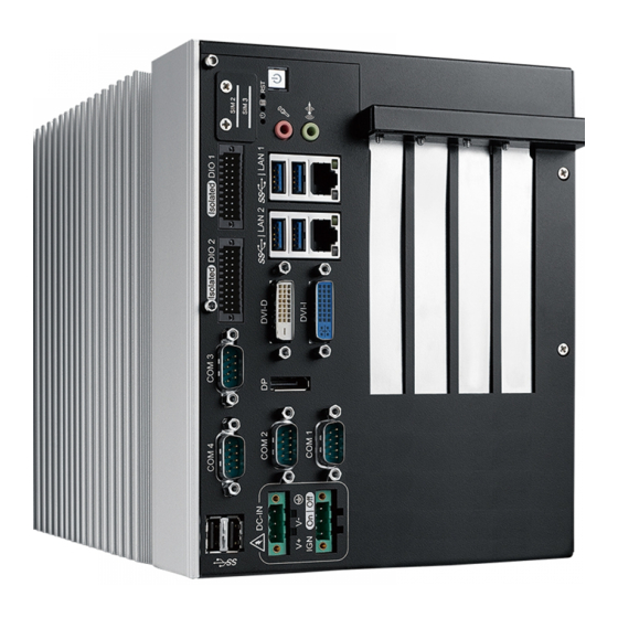
Front Panel I/O Functions
Main Board Expansion Connectors
Main Board Jumper Settings
Ignition Control
Chapter 3 System Setup
How to Open Your RCS-9000/9000F
How to Open Your RCS-9000
How to Open Your RCS-9000F
Installing CPU
Installing DDR4 SO-DIMM Modules
Installing Mini Pcie Card
Installing Antenna Cable
Installing Cfast Card
Installing SIM Card
Installing Pci/Pcie Card
Installing SSD/HDD
Mounting RCS-9000
Chapter 4 Bios and Driver Setting
BIOS Settings
Main Menu
Advanced Function
Chipset Functions
Security
Boot
Save & Exit
APPENDIX A : Isolated DIO Guide
APPENDIX B : Software Functions
APPENDIX C : RAID Installation Guide
APPENDIX D1 : Power Consumption
D2 : Power Consumption
With GTX-1080
APPENDIX E : Supported Memory & Storage List
APPENDIX F : Graphics Performance
APPENDIX G : Install Win11 (BIOS TPM Setting)
Advertisement
Quick Links
Download this manual
RCS-9000
Intel
®
Xeon
®
/Core™ i7/i5/i3 Fanless Robust Computing System
High Performance, Flexible, Expandable, Extended Temperature
USER
USER
Manual
Manual
1.9.0 Edition 20220525
Table of
Contents
Previous
Page
Next
Page
1
2
3
4
5
Advertisement
Table of Contents
Need help?
Do you have a question about the RCS-9000 and is the answer not in the manual?
Ask a question
Questions and answers
Related Manuals for Vecow RCS-9000
Desktop Vecow RCS-70000 User Manual
Fanless robust computing system with 4 pci/pcie slots, 3rd gen. intel core i7/ i5/ i3 mobile processor (106 pages)
Desktop Vecow RCS-9430F-GTX1080 User Manual
Intel xeon/core i7 gpu computing system with nvidia geforce gtx1080 workstation-grade performance, expandable, independent graphics, rcs-9000f gtx1080 series (142 pages)
Desktop Vecow RCX-1000 User Manual
Intel, xeon, core i7/i5/i3 expandable robust computing system workstation-grade, flexible, fanless, extended temperature (160 pages)
Desktop Vecow RMS-1000 User Manual
Intel core i7/i5/i3 soc whiskey lake 1u rackmount fanless computing system, 8 gige lan w/6 x-coded m12, 4 10g usb, ignition control, -40 degrees c to 70 degrees c (73 pages)
Desktop Vecow RCX-1500 PEG User Manual
Intel xeon/core i7/i5/i3 dual gpu ai computing system workstation-grade, nvidia tesla/quadro/geforce graphics (112 pages)
Desktop Vecow RCS-9211 User Manual
Fanless robust computing system (172 pages)
Desktop Vecow RAC-1000 Series User Manual
Nvidia jetson agx orin rugged ai computing system 6 gige lan with 4 poe+, 8 gmsl2, 1 pcie x8, -25 c to 70 c operation (34 pages)
Desktop Vecow ECS-9000 User Manual
Quad core intel core i7/i5/i3 w/c236 fanless embedded system high performance, rugged, -40c to 75c extended temp (127 pages)
Desktop Vecow MTC-6000 User Manual
Intel core i7/i5/i3 fanless multi-touch computer, 6 gigabit lan with 4 poe+/2 pd lan, 2 sim socket, 5 usb 3.0 (118 pages)
Desktop Vecow EVS-2000 Series User Manual
Intel 10th gen. xeon/core i9/i7/i5/i3 fanless ai computing system with nvidia/amd mxm gpu graphics, high performance expandable (131 pages)
Desktop Vecow ECS-9755-505MGTX950 User Manual
Gpu computing systems (111 pages)
Desktop Vecow ECX-2600 PEG User Manual
10th gen intel xeon/core i9/i7/i5/i3 ai computing system workstation-grade, nvidia tesla/quadro/geforce graphics (144 pages)
Desktop Vecow EAC-5000 User Manual
(65 pages)
Desktop Vecow ECS-9740-505M-GTX1050 User Manual
Quad core intel xeon / core i7 processor embedded system with intel cm236 & nvidia geforce gtx1050 ti / gtx1050 graphics, high performance, independent graphics, all-in-one integrated (111 pages)
Desktop Vecow MTC-4021 User Manual
21.5” fanless multi-touch computer, 6 gbe lan with 4 poe+, 2 sim, 4 usb, intel core i7/i5/i3 processor (broadwell-u) (73 pages)
Desktop Vecow TGS-1000 User Manual
Intel core ultra processor ultra-compact stackable ai pc 2.5g lan, usb 3.2 type-c, dc12v to 24v, 0c to 55c (111 pages)
This manual is also suitable for:
Rcs-9440
Rcs-9440h
Rcs-9422
Rcs-9422h
Rcs-9404
Rcs-9404h
...
Show all
Rcs-9440r
Rcs-9440rh
Rcs-9422r
Rcs-9422rh
Rcs-9404r
Rcs-9404rh
Rcs-9220a
Rcs-9220ah
Rcs-9220
Rcs-9220h
Rcs-9211
Rcs-9211h
Rcs-9430f
Rcs-9430fh
Rcs-9430fr
Rcs-9430fhr
Rcs-9421f
Rcs-9421fh
Rcs-9421 fr
Rcs-9421 fhr
Rcs-9412f
Rcs-9412fh
Rcs-9412fr
Rcs-9412fhr
Table of Contents
Print
Rename the bookmark
Delete bookmark?
Delete from my manuals?
Login
Sign In
OR
Sign in with Facebook
Sign in with Google
Upload manual
Upload from disk
Upload from URL


Need help?
Do you have a question about the RCS-9000 and is the answer not in the manual?
Questions and answers