Table of Contents

Related Manuals for Vecow ECS-9200


Summary of Contents for Vecow ECS-9200
- Page 1 USER USER ECS-9200/9100 GTX950 Manual Manual Quad Core Intel ® Xeon ® / Core ™ i7 Processor Embedded System with Intel ® C236 Chipset & NVIDIA GEFORCE ® GTX 950 Graphics High Performance, Independent Graphics, EN50155 1.1.0 Edition 20170718...
- Page 2 Record of Revision Version Date Page Description Remark 05/25/2017 Official Release 07/18/2017 22,76-77 Update...
-
Page 3: Declaration Of Conformity
This manual is released by Vecow Co., Ltd. for reference purpose only. All product offerings and specifications are subject to change without prior notice. It does not represent commitment of Vecow Co., Ltd. Vecow shall not be liable for direct, indirect, special, incidental, or consequential damages arising out of the use of the product or documentation or any infringements upon the rights of third parties, which may result from such use. - Page 4 Order Information Part Number Description ® ECS-9200, NVIDIA GeForce GTX 950, 6 GigE LAN w/4 X-coded ECS-9204MX- M12 PoE , 2 SSD Tray, 8 USB 3.0, 4 COM, 1 M2DOM, 3 SIM, GTX950 32 Isolated DIO ® ECS-9200, NVIDIA GeForce...
- Page 5 Order Accessories Part Number Description ® ® E3-1275 v6 7th Generation Intel Xeon E3-1275 v6 Processor (8M Cache, up to 4.20 GHz, 80W) ® ® E3-1275 v5 6th Generation Intel Xeon E3-1275 v5 Processor (8M Cache, up to 4.00 GHz, 80W) ®...
-
Page 6: Table Of Contents
2.4 Main Board Expansion Connectors 2.5 Main Board Jumper & Deep Switch Settings 2.6 Ignition Control CHAPTER 3 SYSTEM SETUP 3.1 How to Open Your ECS-9200/9100 GTX950 3.2 Installing CPU 3.3 Installing DDR4 SO-DIMM Modules 3.4 Installing Mini PCIe Card... - Page 7 3.5 Installing CFast Card 3.6 Installing SIM Card 3.7 Installing SSD/HDD 3.8 Installing M.2 3.9 Installing M2DOM 3.10 Mounting Your ECS-9200/9100 GTX950 CHAPTER 4 BIOS SETUP 4.1 Entering BIOS SETUP 4.2 Main 4.3 Advanced 4.4 Chipset 4.5 Security 4.6 Boot 4.7 Save &...
-
Page 8: Chapter 1 General Introduction
OpenCL 2.0 API, featuring multiple DVI-D, DVI-I, DisplayPort and HDMI display interfaces support up to 7 independent HD displays and even 5 independent Ultra HD 4K displays, ECS-9200/9100 GTX950 offers more than 460% improved graphics performance than the one without an independent graphics engine;... -
Page 9: Features
4 COM RS-232/422/485 w/auto flow control (ESD 8KV) • 8 USB 3.0 (External) • 1 USB 2.0 (Internal) Isolated DIO 32 Isolated DIO (16 DI, 16 DO) Power, HDD, Wireless, PoE SIM Card 3 External SIM Card Socket ©Vecow ECS-9200/9100 GTX950 User Manual GENERAL INTRODUCTION... - Page 10 Expansion Mini PCIe 3 Full-size for PCIe/USB/External SIM Card/mSATA 1 M.2 Socket (Key ID : M) Graphics ® Processor • Intel HD Graphics 630/530 ® ® • NVIDIA GeForce GTX 950 Interface 8 Display interfaces : • 1 DVI-D : Up to 1920 x1200 @ 60 Hz •...
-
Page 11: Specifications Of Ecs-9204M Gtx950
® Processor Quad Core 7th/6th Generation Intel Xeon /Core™ i7 Processor (Kaby Lake-S/Skylake-S) ® Chipset Intel C236 BIOS IT8786E Memory • DDR4 2133MHz • Up to 32GB • 2 260-pin SO-DIMM Socket (ECC/Non-ECC) ©Vecow ECS-9200/9100 GTX950 User Manual GENERAL INTRODUCTION... - Page 12 I/O Interface Serial 4 COM RS-232/422/485 w/auto flow control (ESD 8KV) • 8 USB 3.0 (External) • 1 USB 2.0 (Internal) Isolated DIO 32 Isolated DIO (16 DI, 16 DO) Power, HDD, Wireless, PoE SIM Card 3 External SIM Card Socket Expansion Mini PCIe 3 Full-size for PCIe/USB/External SIM Card/mSATA...
- Page 13 Relative Humidity 95% at 60°C Shock • IEC 60068-2-27 • SSD : 50G @ Wallmount, Half-sine, 11ms Vibration • IEC 60068-2-64 • SSD : 5Grms, 5Hz to 500Hz, 3 Axis CE, FCC, EN50155, EN50121-3-2 ©Vecow ECS-9200/9100 GTX950 User Manual GENERAL INTRODUCTION...
-
Page 14: Specifications Of Ecs-9240 Gtx950
1.3.3 Specifications of ECS-9240 GTX950 System ® ® Processor Quad Core 7th/6th Generation Intel Xeon /Core™ i7 Processor (Kaby Lake-S/Skylake-S) ® Chipset Intel C236 BIOS IT8786E Memory • DDR4 2133MHz • Up to 32GB • 2 260-pin SO-DIMM Socket (ECC/Non-ECC) I/O Interface Serial 4 COM RS-232/422/485 w/auto flow control (ESD 8KV) - Page 15 140°F) 65W TDP CPU : Core™ i7 : -40°C to 55°C (-40°F to 131°F) 80W TDP CPU : ® Xeon E3-1275 v6, E3-1275 v5, E3-1225 v5 : -40°C to 45°C (-40°F to 113°F) ©Vecow ECS-9200/9100 GTX950 User Manual GENERAL INTRODUCTION...
-
Page 16: Specifications Of Ecs-9100 Gtx950
Storage Temperature -40°C to 85°C (-40°F to 185°F) Humidity 5% to 95% Humidity, non-condensing Relative Humidity 95% at 60°C Shock • IEC 60068-2-27 • SSD : 50G @ Wallmount, Half-sine, 11ms Vibration • IEC 60068-2-64 • SSD : 5Grms, 5Hz to 500Hz, 3 Axis CE, FCC, EN50155, EN50121-3-2 1.3.4 Specifications of ECS-9100 GTX950 System... - Page 17 Mechanical Dimensions (WxDxH) 260mm x 215mm x 79mm (10.2" x 8.5" x 3.1") Weight 4.5 kg (9.92 lb) Mounting • Wallmount by mounting bracket • DIN Rail Mount (Optional) • 2U Rackmount (Optional) ©Vecow ECS-9200/9100 GTX950 User Manual GENERAL INTRODUCTION...
-
Page 18: Supported Cpu List
Environment Operating Temperature 35W TDP CPU : ® Xeon E3-1268L v5, Core™ i7 : -40°C to 60°C (-40°F to 140°F) 65W TDP CPU : Core™ i7 : -40°C to 55°C (-40°F to 131°F) 80W TDP CPU : ® Xeon E3-1275 v6, E3-1275 v5, E3-1225 v5 : -40°C to 45°C (-40°F to 113°F) Storage Temperature -40°C to 85°C (-40°F to 185°F) -
Page 19: Mechanical Dimension
1.5 Mechanical Dimension 1.5.1 Dimensions of ECS-9204MX GTX950 297.0 (11.69”) 282.0 (11.10”) 260.0 (10.24”) Unit: mm (inch) 1.5.2 Dimensions of ECS-9204M GTX950 297.0 (11.69”) 282.0 (11.10”) 260.0 (10.24”) Unit: mm (inch) ©Vecow ECS-9200/9100 GTX950 User Manual GENERAL INTRODUCTION... -
Page 20: Dimensions Of Ecs-9240 Gtx950
1.5.3 Dimensions of ECS-9240 GTX950 297.0 (11.69”) 282.0 (11.10”) 260.0 (10.24”) Unit: mm (inch) 1.5.4 Dimensions of ECS-9100 GTX950 297.0 (11.69”) 282.0 (11.10”) 260.0 (10.24”) Unit: mm (inch) GETTING TO KNOW YOUR ECS-9200/9100 GTX950... -
Page 21: Ecs-9200/9100 Gtx950
2.1 Packing List Item Description ECS-9200/9100 GTX950 Embedded System (According to the configuration you order, the ECS-9200/9100 GTX950 series may contain SSD/HDD and DDR4 SO-DIMM. Please verify these items if necessary.) ECS-9204M/9204MX GTX950 Accessory box, which contains ● Vecow Drivers & Utilities DVD ●... -
Page 22: Front Panel I/O & Functions
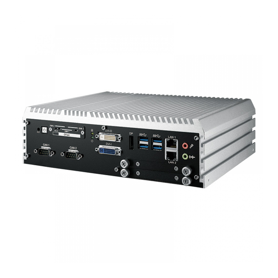
2.2 Front Panel I/O & Functions In Vecow ECS-9200/9100 GTX950 series family, all I/O connectors are located on the front panel and the rear panel. Most of the general connections to computer device, such as USB, LAN Jack, Audio, Display Port, DVI-I, DVI-D and other additional storage, are placed on the front panel. -
Page 23: Cfast Card
It is implemented by a SATA III Port from C236 PCH. Be sure to disconnect the power source and unscrew the CFast socket cover before installing a CFast card. The ECS-9200/9100 GTX950 does not support the CFast hot swap and PnP (Plug and Play) functions. It is necessary to remove power source first before inserting or removing the CFast card. - Page 24 DVI signal. The DVI output mode supports up to 1920 x 1200 resolution and the DVI is automatically selected according to the display device connected. You will need a DVI-D cable when connecting to a display device. GETTING TO KNOW YOUR ECS-9200/9100 GTX950...
- Page 25 LAN 2 Onboard Display Port supports auxiliary channel dual mode and the connection supports up to 4096 x 2304 resolution at 60 Hz. Multi-Stream Transport Display Resolutions Table as follows: ©Vecow ECS-9200/9100 GTX950 User Manual GETTING TO KNOW YOUR ECS-9200/9100 GTX950...
-
Page 26: Ethernet Port
There are 4 USB 3.0 connections available supporting up to 5GB per second data rate in the front side of ECS-9200/9100 GTX950. It is also compliant with the requirements of Super Speed (SS), High Speed (HS), Full Speed (FS) and Low Speed (LS). -
Page 27: Audio Jack
HD audio and fully complies with Intel High Definition Audio (Azalia) specifications. To utilize the audio function in Windows platform, you need to install the corresponding drivers for both Intel C236 chipset and Realtek ALC892 codec. ©Vecow ECS-9200/9100 GTX950 User Manual GETTING TO KNOW YOUR ECS-9200/9100 GTX950... - Page 28 Mini PCIe Slot/SIM Slot/WLAN LED Mapping Table : Mini PCIe Mini PCIe 1 SIM 1 (CN12) Mini PCIe 2 SIM 2 (CN13) Mini PCIe 3 SIM 3 (CN11) Mini PCIe 3 Mini PCIe 2 Mini PCIe 1 CN11 CN12 CN13 GETTING TO KNOW YOUR ECS-9200/9100 GTX950...
-
Page 29: System Fan
DVI-I LAN 2 There is a system FAN on front side for airflow direction outward. You can adjust the FAN Speed from Vecow BIOS Setting. (refer to 4.3.6_Hardware Monitor_FAN PWM Value) ©Vecow ECS-9200/9100 GTX950 User Manual GETTING TO KNOW YOUR ECS-9200/9100 GTX950... -
Page 30: Rear Panel I/O & Functions
You could turn on or off the system power by using this contact. This terminal block supports dual functions of soft power-on/power-off (instant off or delay 4 second) and suspend mode. Pin No. Definition Pin No. Definition Ignition External Power Button V+ External Power Button V- GETTING TO KNOW YOUR ECS-9200/9100 GTX950... -
Page 31: Com Ports
(9-wire) (3-wire) TXD- TXD- DATA- TXD+ TXD+ DATA+ RXD+ RXD+ ----------- RXD- RXD- ----------- 1 to 4 ----------- RTS- ----------- ----------- RTS+ ----------- ----------- CTS+ ----------- ----------- CTS- ----------- ©Vecow ECS-9200/9100 GTX950 User Manual GETTING TO KNOW YOUR ECS-9200/9100 GTX950... - Page 32 COM3 & COM 4 MB connector table: COM Port MB Connector COM Port MB Connector COM 3 COM 4 CN10 COM 3 & COM 4 MB connector pin out: Pin No. Signal Name Chassis GND CN9 (COM3) CN10 (COM4) CN10 GETTING TO KNOW YOUR ECS-9200/9100 GTX950...
- Page 33 There are 4 USB 3.0 connections available supporting up to 5GB per second data rate in the rear side of ECS-9200/9100 GTX950. It is also compliant with the requirements of Super Speed (SS), High Speed (HS), Full Speed (FS) and Low Speed (LS).
- Page 34 Green Light: PD installed & powered green LAN4 Green Off: Non PD Green Light: PD installed & powered green LAN5 Green Off: Non PD Green Light: PD installed & powered green LAN6 Green Off: Non PD GETTING TO KNOW YOUR ECS-9200/9100 GTX950...
- Page 35 DIO1_GND OUTPUT 0 SIO_GPO70 OUTPUT 1 SIO_GPO71 OUTPUT 2 SIO_GPO72 OUTPUT 3 SIO_GPO73 OUTPUT 4 SIO_GPO74 OUTPUT 5 SIO_GPO75 OUTPUT 6 SIO_GPO76 OUTPUT 7 SIO_GPO77 DIO1_GND DIO1_VDC (6~48V Input) ©Vecow ECS-9200/9100 GTX950 User Manual GETTING TO KNOW YOUR ECS-9200/9100 GTX950...
- Page 36 DIO2_VDC (6~48V Input) DI reference circuit: Sink Mode (NPN) Power DIO Connector Supply DI_COM (Pin 9) 6-48V DC DI (Pin1-8) Source Mode (PNP) Power DIO Connector Supply DI_COM (Pin 9) 6-48V DC DI (Pin1-8) GETTING TO KNOW YOUR ECS-9200/9100 GTX950...
- Page 37 You could have 4 independent displays as your wish from these 5 display ports. Also, you could have four 4K resolution displays, the 3 Display Port and a HDMI, from these 5 ports. ©Vecow ECS-9200/9100 GTX950 User Manual GETTING TO KNOW YOUR ECS-9200/9100 GTX950...
-
Page 38: Main Board Expansion Connectors
2.4 Main Board Expansion Connectors 2.4.1 Inside View of ECS-9200/9100 GTX950 Main Board With Connector Location CN10 CN15 CN25 FAN2 JP10 CN18 SATA2 SATA1 FAN1 SODIMM 2 SODIMM 1 Mini PCIe 2 Mini PCIe 3 M2_CN2 Mini PCIe 1 BIOS... - Page 39 LED indicator, reset button, power LED indicator, and power-on/ off button, which already can be accessed by front panel and top panel. The pin-outs of Miscellaneous port are listed in following table: ©Vecow ECS-9200/9100 GTX950 User Manual GETTING TO KNOW YOUR ECS-9200/9100 GTX950...
- Page 40 2.4.4 DDR4 Slot There are 2 DDR4 channel onboard supporting DDR4 2133/1866 and up to 32GB. (Each channel 16GB) SODIMM 2 SODIMM 1 Slot Description Slot Description SODIMM_1 DDR4 Channel A SODIMM_2 DDR4 Channel B GETTING TO KNOW YOUR ECS-9200/9100 GTX950...
-
Page 41: Sata Connector
2.4.5 BIOS Socket If the BIOS needs to be changed, please contact the Vecow RMA service team. BIOS 2.4.6 SATA Connector Standard 7 PIN SATA Connector There are 2 onboard high performance Serial ATA III. It supports higher storage capacity with less cabling effort and smaller required space. - Page 42 2.4.8 Internal USB2.0 Standard Vertical USB2.0 Connector The ECS-9200/9100 GTX950 main board provides one expansion USB port using plug-and-play for Dongle Key or LCD touch Panel. The USB interface supports 480 Mbps transfer rate complied with high speed USB specification Rev.
- Page 43 Support hot removal: The removal of a SATA device from a powered backplane, without first being placed in a quiescent state. M2_CN1 Model No. Definition S20 / S30 16GB M2DOM 3ME3 S20 / S30 32GB S20 / S30 64GB 128GB ©Vecow ECS-9200/9100 GTX950 User Manual GETTING TO KNOW YOUR ECS-9200/9100 GTX950...
- Page 44 Standard Type 2280 M.2 (M key) slot: M2_CN2 Pin Out: Pin No. Function Pin No. Function +3.3V +3.3V PEDET (NC-PCIe/GND- +3.3V SATA) Mechanical Key REFCLKp REFCLKn WAKE# CLKREQ# PETp0 /SATA-A+ PERST# PETn0 /SATA-A- PERp0 /SATA-B- PERn0 /SATA-B+ PETp1 DEVSLP PETn1 GETTING TO KNOW YOUR ECS-9200/9100 GTX950...
- Page 45 PETp3 +3.3V PETn3 +3.3V DAS/DSS# (I/O)/LED1# (I)(0/3.3V) PERp3 PERn3 +3.3V +3.3V 2.4.11 Mini PCIe Standard full length Mini PCIe slot: Mini PCIe 2 Mini PCIe 3 Mini PCIe 1 ©Vecow ECS-9200/9100 GTX950 User Manual GETTING TO KNOW YOUR ECS-9200/9100 GTX950...
- Page 46 Reserved Reserved +3.3Vaux Reserved +3.3Vaux USB_D+ USB_D- PETp0 PETn0 SMB_DATA SMB_CLK +1.5V PERn0 PERp0 +3.3Vaux PERST# Reserved reserved Reserved Mechanical Key UIM_VPP REFCLK+ UIM_RESET REFCLK- UIM_CLK UIM_DATA CLKREQ# UIM_PWR Reserved 1.5V Reserved WAKE# 3.3Vaux GETTING TO KNOW YOUR ECS-9200/9100 GTX950...
- Page 47 The system’s real-time clock is powered by a lithium battery. It is equipped with Panasonic BR2032 190mAh lithium battery. It is recommended that you do not have to get the lithium battery on your own. If the battery needs to be changed, please contact the Vecow RMA service team. Battery 2.4.13 FAN Header Fan power connector supports for additional thermal requirements.
- Page 48 2.4.14 LPC Port 80 Header ECS-9200/9100 GTX950 provides a LPC Port 80 Header for Debug Card. Pin out: Pin No. Function Pin No. Function SERIRQ LFRAME# +3.3V LAD0 RESET# Ground LAD1 CLOCK LAD2 Ground 2.4.15 LAN IEEE 1588 Header ECS-9200 GTX950 provides a LAN header for IEEE 1588.
- Page 49 Pin No. Function Pin No. Function SPD0 SPD1 SPD2 SPD3 Ground Ground 2.4.16 COM Port Header ECS-9200/9100 GTX950 provides 4 COM port headers for internal COM port cable. CN10 Pin out: CN9: CN10: Pin No. Description Port Pin No. Description...
-
Page 50: Main Board Jumper & Deep Switch Settings
Battery M2_CN1 The figure below is the top view of ECS-9200/9100 GTX950 main board which is the main board. It shows the location of the jumpers and the switches. You may configure your card to match the needs of your application by setting jumpers. - Page 51 1 : ON 1 : ON 2 : OFF 2 : OFF 2 : ON 2.5.2 USB Power Jumper Jumper Setting Function Supported Wake Up(Default) Non Wake Up support ©Vecow ECS-9200/9100 GTX950 User Manual GETTING TO KNOW YOUR ECS-9200/9100 GTX950...
- Page 52 COM2 +12V (0.5A max.) RI (Default) Pin Header Pin No. Description +5V (1A max.) COM3 +12V (0.5A max.) RI (Default) Pin Header Pin No. Description +5V (1A max.) COM4 +12V (0.5A max.) RI (Default) GETTING TO KNOW YOUR ECS-9200/9100 GTX950...
- Page 53 POE power on at standby power ready JP10 POE power on after system power on (Default) 2.5.5 Clear CMOS/ME Switch Jumper Setting Function *Normal(Default) Clear CMOS Jumper Setting Function *Normal(Default) Clear ME ©Vecow ECS-9200/9100 GTX950 User Manual GETTING TO KNOW YOUR ECS-9200/9100 GTX950...
-
Page 54: Ignition Control
2.6 Ignition Control ECS-9200/9100 GTX950 series provides ignition power control feature for in- vehicle applications. The built-in MCU monitors the ignition signal and turns on/ off the system according to pre-defined on/off delay period. 2.6.1 Adjust Ignition Control Modes ECS-9200/9100 GTX950 series provides 16 modes of different power on/off delay periods adjustable via SW2 switch. - Page 55 30 minutes 5 seconds 1 hour 10 seconds 2 hours 10 seconds 4 hours 10 seconds 6 hours 10 seconds 8 hours 10 seconds 12 hours 10 seconds 24 hours ©Vecow ECS-9200/9100 GTX950 User Manual GETTING TO KNOW YOUR ECS-9200/9100 GTX950...
- Page 56 Note: 1. DC power source and IGN share the same ground. 2. ECS-9200/9100 GTX950 supports 6V~36V wide range DC power input in ATX/AT mode. In Ignition mode, the input voltage is fixed to 12V/24V for car battery scenario.
- Page 57 The Low Battery Detection is implemented in the ignition control MCU FW and as a default function. Note: Battery Voltage Thresholds 10.5~15V 21.5~30V ©Vecow ECS-9200/9100 GTX950 User Manual GETTING TO KNOW YOUR ECS-9200/9100 GTX950...
-
Page 58: Chapter 3 System Setup
SYSTEM SETUP 3.1 How to Open Your ECS-9200/9100 GTX950 Step 1 Remove hole plugs. Step 2 Remove two F#6-32 screws (circled in red) and two F-M3 screws (circled in yellow) on the bottom side. HARDWARE INSTALLATION... - Page 59 Step 3 Finish Step1 and 2. Step 4 Remove one KHS#6-32x6 screw. Step 5 Open the module. ©Vecow ECS-9200/9100 GTX950 User Manual HARDWARE INSTALLATION...
- Page 60 Step 6 Finish. Step 7 Remove two F-#6-32 screws at the bottom side. Step 8 Remove the cover. Remove one screw KHS-#6-32 and SSD/ HDD tray at front panel. HARDWARE INSTALLATION...
- Page 61 Step 9 Remove SSD/HDD module. Step 10 Be careful pulling out SATA(yellow), power SATA(blue) and COM cables(red) . Step 11 Remove four KHS-#6-32 screws at the rear panel. ©Vecow ECS-9200/9100 GTX950 User Manual HARDWARE INSTALLATION...
-
Page 62: Installing Cpu
Step 12 Finish. 3.2 Installing CPU Step 1 Remove one F #6-32 and pick up chock bracket. Step 2 Remove eight PH-M3 and four M3x11 spring screws and pick up mother board. HARDWARE INSTALLATION... - Page 63 Step 3 CPU socket. Step 4 Open the CPU socket. (Be careful CPU pins) ©Vecow ECS-9200/9100 GTX950 User Manual HARDWARE INSTALLATION...
- Page 64 Step 5 Install CPU on the socket. Step 6 Finish. Step 7 Close CPU socket and finish. HARDWARE INSTALLATION...
-
Page 65: Installing Ddr4 So-Dimm Modules
3.3 Installing DDR4 SO-DIMM Modules Step 1 DDR4 RAM module into SO-DIMM slot. Step 2 Make sure the RAM module is locked by the memory slot. ©Vecow ECS-9200/9100 GTX950 User Manual HARDWARE INSTALLATION... -
Page 66: Installing Mini Pcie Card
3.4 Installing Mini PCIe Card Step 1 Install Mini PCIe card into the Mini PCIe socket. Step 2 Fasten one M2.5 screw. HARDWARE INSTALLATION... -
Page 67: Installing Cfast Card
Step 2 Before inserting CFast & SIM Cards, make sure the system power is not plugged. Step 3 Insert CFast card and push to lock. Step 4 Insert CFast card and push to lock. ©Vecow ECS-9200/9100 GTX950 User Manual HARDWARE INSTALLATION... -
Page 68: Installing Sim Card
3.6 Installing SIM Card Step 1 Remove 2 pcs F-M3x4 screws on CFast & SIM Cards. Step 2 Before inserting CFast & SIM Cards, make sure the system power is not plugged. Step 3 Insert SIM card and push to lock. Step 4 Insert SIM card and push to lock. -
Page 69: Installing Ssd/Hdd
3.7 Installing SSD/HDD Step 1 Trigger and open SSD/HDD tray. Step 2 Insert 2.5” SSD/HDD in the tray and fasten two F-M3x4 screws. ©Vecow ECS-9200/9100 GTX950 User Manual HARDWARE INSTALLATION... - Page 70 Step 3 Finish. Step 4 Installing SSD/HDD. HARDWARE INSTALLATION...
-
Page 71: Installing
3.8 Installing M.2 Step 1 M.2 slot. Step 2 Fasten one M3 screw. ©Vecow ECS-9200/9100 GTX950 User Manual HARDWARE INSTALLATION... -
Page 72: Installing M2Dom
3.9 Installing M2DOM Step 1 M2DOM slot. Step 2 M2DOM module. HARDWARE INSTALLATION... - Page 73 Step 3 Install M2DOM module with slot. Step 4 Lock two M2 screws with slot. ©Vecow ECS-9200/9100 GTX950 User Manual HARDWARE INSTALLATION...
-
Page 74: Mounting Your Ecs-9200/9100 Gtx950
3.10 Mounting Your ECS-9200/9100 GTX950 3.10.1 Wall Mount Bracket Step 1 Ensure the screw holes on the right and left side of the upper case match the ones on ECS-9200/9100 GTX950 wall mount bracket. HARDWARE INSTALLATION... -
Page 75: Vesa Mount
Step 2 Fasten 4pcs KHS#6-32 screws and then finish. 3.10.2 VESA Mount Step 1 ECS-9200/9100 GTX950 and VESA Mount. ©Vecow ECS-9200/9100 GTX950 User Manual HARDWARE INSTALLATION... - Page 76 Step 2 Take ECS-9200/9100 GTX950 and VESA Mount with fasten 4pcs KHS#6-32 screws. Step 3 Fasten four KHS#6-32 screws and then finish. HARDWARE INSTALLATION...
- Page 77 Step 4 Finish. Step 5 There are two sizes of VESA, 75x75mm(red) and 100x100mm(yellow). ©Vecow ECS-9200/9100 GTX950 User Manual HARDWARE INSTALLATION...
- Page 78 3.10.3 Din Rail Kit Step 1 ECS-9200/9100 GTX950 and Din Rail Kit. Step 2 Take ECS-9200/9100 GTX950 and Din Rail Kit and fasten four KHS#6-32 screws in the four marked corners. HARDWARE INSTALLATION...
- Page 79 Step 3 Fasten four KHS#6-32 screws and then finish. Step 4 Finish. Step 5 ECS-9200/9100 GTX950 With Din Rail. ©Vecow ECS-9200/9100 GTX950 User Manual HARDWARE INSTALLATION...
-
Page 80: Chapter 4 Bios Setup
BIOS SETUP 4.1 Entering BIOS SETUP Figure 4-1: Entering Setup Screen BIOS provides an interface for users to check and change system configuration. The BIOS setup program is accessed by pressing the <Del> key when POST display output is shown. BIOS AND DRIVER SETTING... -
Page 81: Main
Set the time. Use <Tab> to switch between time elements. 4.3 Advanced Figure 4 3: BIOS Advanced Menu Select advanced tab to enter advanced BIOS setup options such as CPU configuration, SATA configuration, and USB configuration. ©Vecow ECS-9200/9100 GTX950 User Manual BIOS AND DRIVER SETTING... -
Page 82: Acpi Settings
4.3.1 ACPI Settings Figure 4 3-1: ACPI Settings Enable Hibernation Enables or disables system's ability to hibernate (OS/S4 sleep state). This option may not be effective with some OS. ACPI Sleep State Selects the highest ACPI sleep state the system will enter when the SUSPEND button is pressed. - Page 83 4.3.5 IT8786 Super IO Configuration Figure 4-3-5: Super IO Settings Serial Port 1 Configuration Set parameters of serial port 1 (COM 1). Serial Port 2 Configuration Set parameters of serial port 2 (COM 2). ©Vecow ECS-9200/9100 GTX950 User Manual BIOS AND DRIVER SETTING...
-
Page 84: Hardware Monitor
Serial Port 3 Configuration Set parameters of serial port 3 (COM 3). Serial Port 4 Configuration Set parameters of serial port 4 (COM 4). 4.3.6 Hardware Monitor Figure 4 3-6: Hardware Monitor Settings The IT8786 SIO features an enhanced hardware monitor providing thermal, fan speed, and system voltages' status monitoring. - Page 85 Enable/disable CPU Advanced Encryption Standard instructions. Boot performance mode Select the performance state that the BIOS will set before OS handoff. Intel(R) SpeedStep(tm) Allows more than two frequency ranges to be supported. Turbo Mode Turbo Mode. ©Vecow ECS-9200/9100 GTX950 User Manual BIOS AND DRIVER SETTING...
-
Page 86: Sata Configuration
CPU C state Enable or disable CPU C states. Enhanced C-states Enable/disable C1E. When enabled, CPU will switch to minimum speed when all cores enter C-State. Package C State limit Package C State limit. Intel TXT(LT) Support Enables or disables Intel (R) TXT (LT) support. 4.3.9 Intel TXT Information Figure 4 3-9: Intel TXT Information Display Intel TXT information. - Page 87 Identifies that the SATA port is connected to solid state drive or hard disk drive. 4.3.11 Acoustic Management Configuration Figure 4 3-11: Acoustic Management Settings Acoustic Management Configuration Option to enable or disable automatic acoustic management. ©Vecow ECS-9200/9100 GTX950 User Manual BIOS AND DRIVER SETTING...
- Page 88 4.3.12 CSM Configuration Figure 4 3-12: CSM Settings CSM Support Enable/disable CSM support GateA20 Active UPON REQUEST - GA20 can be disabled using BIOS services. ALWAYS - do not allow GA20 to be disabled; this option is useful when any RT code is executed above 1MB.
- Page 89 Maximum time the device will take before it properly reports itself to the Host Controller. 'Auto' uses default value, for a root port it is 100 ms, for a hub port the delay is taken from the hub descriptor. ©Vecow ECS-9200/9100 GTX950 User Manual BIOS AND DRIVER SETTING...
-
Page 90: Chipset
4.4 Chipset Figure 4-4: BIOS Chipset Menu System Agent (SA) Configuration System Agent (SA) parameters. PCH-IO Configuration PCH parameters. GPIOManager Configuration GPIOManager parameters. 4.4.1 System Agent (SA) Configuration Figure 4-4-1: System Agent Settings VT-d VT-d capability. GMM Device (B0:D8:F0) Enable/disable SA GMM device. Above 4GB MMIO BIOS assignment Enable/disable above 4GB MemoryMappedIO BIOS assignment. - Page 91 Select DVMT5.0 Total Graphic Memory size used by the Internal Graphics Device. Cd Clock Frequency Select the highest Cd Clock frequency supported by the platform. 4.4.3 PEG Port Configuration (SA) Figure 4-4-3: PEG Port Configuration PEG port options for PCIe device. ©Vecow ECS-9200/9100 GTX950 User Manual BIOS AND DRIVER SETTING...
- Page 92 4.4.4 Memory Information of System Agent (SA) Figure 4-4-4: Memory Information Displays memory information. 4.4.5 PCH-IO Configuration Figure 4-4-5: PCH-IO Settings PCH LAN Controller Enable or disable onboard NIC. Wake on LAN Enable or disable integrated LAN to wake the system. (The wake On LAN cannot be disabled if ME is on at Sx state.) Serial IRQ Mode Configure serial IRQ mode.
- Page 93 PCI Express Native Support Enable/Disable. This feature is available in vista and beyond Windows OS. 4.4.7 BIOS Security Configuration of PCH-IO Figure 4-4-7: BIOS Security Settings BIOS Lock Enable/disable the PCH BIOS Lock Enable (BLE bit) feature. ©Vecow ECS-9200/9100 GTX950 User Manual BIOS AND DRIVER SETTING...
- Page 94 4.4.8 SB Porting Configuration of PCH-IO Figure 4-4-8: RAID ROM Settings SATA RAID ROM Legacy ROM: Legacy option ROM UEFI Driver: UEFI Raid Driver Both: Run the Legacy Option ROM and UEFI driver. 4.4.9 GPIO Manager Configuration Figure 4-4-9: GPIO Manager Settings VGA Enable Enable: VGA display output enabled Disable: VGA display output disabled...
-
Page 95: Security
Discard or save changes option in setup does not have any impact on HDD when password is set or removed. If the 'Set HDD User Password' option is gray, do power cycle to enable the option again. ©Vecow ECS-9200/9100 GTX950 User Manual BIOS AND DRIVER SETTING... -
Page 96: Boot
4.6 Boot Figure 4-6: BIOS Boot Menu Setup Prompt Timeout Number of seconds to wait for setup activation key. 65535(0xFFFF) means indefinite waiting. Bootup NumLock State Select the keyboard NumLock state. Quiet Boot Enables or disables Quiet Boot option. Boot Option Sets the system boot order. -
Page 97: Save & Exit
Restore/load default values for all the setup options. Save as User Defaults Save the changes done so far as user defaults. Restore User Defaults Restore the user defaults to all the setup options. ©Vecow ECS-9200/9100 GTX950 User Manual BIOS AND DRIVER SETTING... -
Page 98: Appendix A : Isolated Dio Guide
APPENDIX A : Isolated DIO Guide A.1 Function Description The ECS-9700 GTX950 offers two 16-bit DIO (8-DI/ 8-DO) 20-pin terminal block connector. Each bit of DI and DO equipped with a photo-coupler for isolated protection. All IO pins are fixed by Hardware design and cannot change in/out direction in runtime process. - Page 99 Runtime folder include head file for software developer or System Integration. Sample folder include Sample program, Driver package, and Driver API library. Source folder include Sample program source code that compile on Visual Studio 2008. Appendix A ©Vecow ECS-9200/9100 GTX950 User Manual...
- Page 100 Sure you OS before you install it. A.4 DIO Demo Tool Execute DIO demo tool (ECS9K2.exe). ECS-9200 Demo Utility DIO Utilities with driver Operation on DIO / WDT / PoE Demo tool utility. Click “Isolate” checked button for isolate / non-isolated DIO setup (customized version);...
-
Page 101: Appendix B : Software Functions
TRUE (1): Success; FALSE (0): Fail (driver not work, or hardware problem) BOOL GetDI2(BYTE *DI); Get DIO2 input DI: DIO2 input (DI[7:0]) Return: TRUE (1): Success; FALSE (0): Fail (driver not work, or hardware problem) Appendix B ©Vecow ECS-9200/9100 GTX950 User Manual... - Page 102 BOOL SetDO2(BYTE DO); Set DIO2 output DO: DIO2 output (DO[7:0]) Return: TRUE (1): Success; FALSE (0): Fail (driver not work, or hardware problem) BOOL GetDO2(BYTE *DO); Get DIO2 output DO: DIO2 output (DO[7:0]) Return: TRUE (1): Success; FALSE (0): Fail (driver not work, or hardware problem) BOOL GetWDT(DWORD *WDT);...
- Page 103 DO_NPN: DIO2 output NPN mode 1: PNP (Source) mode for European rule; 0: NPN (Sink) mode for Japanese rule Return: TRUE (1): Success; FALSE (0): Fail (driver not work, or hardware problem) Appendix B ©Vecow ECS-9200/9100 GTX950 User Manual...
- Page 104 BOOL Set DIO2Config(BYTE Isolate_Type, BYTE DI_NPN, BYTE DO_NPN); Set DIO2 configuration Isolate_Type: DIO2 Isolate Type 1: Isolated DIO; 0: Non-Isolated DIO DI_NPN: DIO2 input NPN mode (DI_NPN[7:0]) 1: PNP (Source) mode for European rule; 0: NPN (Sink) mode for Japanese rule DO_NPN: DIO2 output NPN mode 1: PNP (Source) mode for European rule;...
-
Page 105: Appendix C : Raid Installation Guide
Please select SATA device to RAID mode on BIOS menu. Advanced → SATA Configuration → SATA Mode Selection C.2 OS Installation ECS-9200/9100 GTX950 is featured with six SATA, include two internal SATA, three mSATA and one CFast. You can select one of SATA ports for OS installation We used CFast card for Windows 10 OS installation as an example. - Page 106 C.6 Create RAID Volume on “Rapid Storage Technology” Software ECS-9200/9100 GTX950 is featured with four SATA HDDs for RAID volume, so there are three options for choose on this page. Let’s take RAID 1 as example, please select ”RAID 1”.
- Page 107 Then add “Logical Device” for Windows access. C.8 If One SATA HDD on RAID Volume is Out-of-use After RAID 1 volume created, you can see the figure of SATA device allocation. HDD CAUTION Sign Appendix C ©Vecow ECS-9200/9100 GTX950 User Manual...
- Page 108 C.9 Recovery and Auto Re-build When Using the SAME RAID HDD C.10 Recovery and Auto Re-build When Using DIFFERENT RAID HDD There is a warning will pop-up to ask you if the disk is not a member of original RAID volume. If you press “Rebuild”, it will replace the broken SATA HDD to the last one SATA HDD of RAID volume.
-
Page 109: Appendix D : Power Consumption
LAN 2 (i210) 1.0 Gbps LAN3 (i210) 1.0 Gbps LAN4 (i210) 1.0 Gbps LAN5 (i210) 1.0 Gbps LAN6 (i210) 1.0 Gbps Graphics Output Power Plan Balance (Windows10 Power Plan) Power Source Chroma 62006P-100-25 Appendix D ©Vecow ECS-9200/9100 GTX950 User Manual... - Page 110 D.1 Intel® Core™ i7-6700 (8M Cache, up to 4.00 GHz) Power on and boot to Win 10 64-bit Idle Status : Sleep Mode CPU usage less 3% Power Input Current Consumption Current Consumption Core™ i7- 0.296A 04.44W 1.794A 26.91W 6700 Core™...
-
Page 111: Appendix E : Supported Memory & Storage List
ECS-9200 GTX950 Memory Test version: 5.1 BurnInTest V8.1 E.2 Test Item Remove Channel Memory Test Burn In Flash BIOS Battery PASS PASS PASS PASS *1(Socket 1) PASS PASS PASS *1(Socket 2) PASS PASS PASS Appendix E ©Vecow ECS-9200/9100 GTX950 User Manual... - Page 112 E.3 NON-ECC Test Temp. Brand Info NOTE & S\N (Celsius) Kingston 16GB BKMM1641607 25ºC 2Rx8 2Gx64-Bit KVR21S15D8/16 BKMM1661618 25ºC PC4-2133 Memxpro 4GB 01611170040001 25ºC DDR4-2133-15 D4S4GHIOFEI 01611170040002 25ºC Wild Temp. Memxpro 8GB 01611150020001 25ºC DDR4-2133-15 D4S8GHIOFFI 01611150020002 25ºC Wild Temp. Memxpro 8GB 01611170030001 25ºC...
- Page 113 M3B MD3MB1164GS1SN 64GB M3B MD3MB11128D2WN 128GB Memxpro SATA SSD M3B MD3MB11128D2SN 128GB M3B MP3MB12256S4WN 256GB M3B MP3MB12256S4SN 256GB ME4ME01128D4SN-M0 128GB M.2 PCIe Memxpro ME4AE02128D4SNR 128GB Transcend CFX600 32GB CFast Silicon SP128GICFX311NV0 128GB Power Appendix E ©Vecow ECS-9200/9100 GTX950 User Manual...
-
Page 114: Appendix F : Graphics Performance
PASS PASS PASS PASS PASS PASS PASS PASS PASS PASS PASS Testing Equipment ® CPU : Intel Core™ i7-6700 IMB : ECS-9200 Memory : MEMXPRO 8GB*2 ** If more help is needed, please contact Vecow technical support ** Appendix F... - Page 115 No part of this publication may be reproduced in any form or by any means, electric, photocopying, or recording, without prior authorization from the publisher. The rights of all the brand names, product names, and trademarks belong to their respective owners. © Vecow Co., Ltd. 2017. All rights reserved.
Need help?
Do you have a question about the ECS-9200 and is the answer not in the manual?
Questions and answers