
Subscribe to Our Youtube Channel
Related Manuals for Vecow VCM-1000


Summary of Contents for Vecow VCM-1000
- Page 1 USER USER VCM-1000 Manual Manual 13th/12th Gen Intel ® Core™ i9/i7/i5/i3 Compact Embedded System 6 GigE LAN w/4 PoE+, 12 USB, DC 24V, -25°C to 75°C Operation Temp. 1.0.0 Edition 20230703...
- Page 2 Record of Revision Version Date Page Description Remark 2023/07/03 Official Release ©Vecow VCM-1000 User Manual...
- Page 3 This manual is released by Vecow Co., Ltd. for reference purpose only. All product offerings and specifications are subject to change without prior notice. Vecow Co., Ltd. is under no legal commitment to the details of this document. Vecow shall not be liable for direct, indirect, special, incidental, or consequential damages arising out of the use of this document, the products, or any third party infringements, which may result from such use.
- Page 4 Order Information Part Number Description VCM-1000, 2 GigE LAN, 2 COM, 4 USB 3.2, 1 SSD Bracket, VCM-1000 Fanless VCM-1000F VCM-1000F, 2 GigE LAN, 2 COM, 4 USB 3.2, 1 SSD Bracket, Fan VCM-1100F, 6 GigE LAN w/4 PoE+, 2 COM, 8 USB 3.2, 28 Isolated...
- Page 5 ® Intel Core™ i3-13100TE ® Intel Core™ i9-12900E ® Intel Core™ i9-12900TE ® Intel Core™ i7-12700E ® Intel Core™ i7-12700TE Intel ® Core™ i5-12500E ® Intel Core™ i5-12500TE ® Intel Core™ i3-12100E ® Intel Core™ i3-12100TE ©Vecow VCM-1000 User Manual...
- Page 6 VESA Mount VESA Mounting Kit DIN-RAIL Kit DIN Rail Kit and VESA Mounting Kit M.2 Storage M.2 Key M Storage Module Module 4G Module 4G/GPS Module with Antenna WiFi & Bluetooth WiFi & Bluetooth Module with Antenna ©Vecow VCM-1000 User Manual...
-
Page 7: Table Of Contents
1.5 Mechanical Dimension 1.5.1 Dimensions of VCM-1000 1.5.2 Dimensions of VCM-1000F 1.5.3 Dimensions of VCM-1100F CHAPTER 2 GETTING TO KNOW YOUR VCM-1000 2.1 Packing List 2.2 Front Panel I/O Functions 2.3 Main Board Expansion Connectors 2.4 Main Board Jumper Settings 2.5 Ignition Control... - Page 8 4.7 Save & Exit APPENDIX A : Isolated DIO Guide APPENDIX B : Software Functions APPENDIX C : Power Consumption (VCM-1100) APPENDIX D : Power Consumption (VCM-1000) APPENDIX E : Supported Memory & Storage List ©Vecow VCM-1000 User Manual viii...
-
Page 9: Chapter 1 General Introduction
4 IEEE 802.3at PoE+, 2 COM ports, and support for up to 12 USB 3.2 connections. Additionally, to meet the growing storage demands of advanced IoT applications, the VCM-1000 Series is equipped with 2 2.5" SSD/HDD slots and 1 M.2 Key M socket. This configuration provides a faster, smaller, and more efficient solution for data-rich applications. -
Page 10: Features
• Software Ignition Control, TPM 2.0, Intel • Compact 2U half-rack design, -25°C to 75°C wide range operating temperature • Optional VHub AIoT Solution Service supports OpenVINO based AI accelerator and advanced Edge AI application ©Vecow VCM-1000 User Manual GENERAL INTRODUCTION... -
Page 11: Product Specification
1.3 Product Specification 1.3.1 Specifications of VCM-1000 System ® • Intel 13th Generation Core™ i9/i7/i5/i3 Processor (Raptor Lake-S) Processor ® • Intel 12th Generation Core™ i9/i7/i5/i3 Processor (Alder Lake-S) ® Chipset Intel H610E BIOS IT8786E • 2 DDR5 4800MHz (Non-ECC) Memory •... - Page 12 5% to 95% humidity, non-condensing Relative Humidity 95% at 60°C • IEC 60068-2-27 Shock • SSD : 50G @ wallmount, Half-sine, 11ms • IEC 60068-2-64 Vibration • SSD : 5Grms, 5Hz to 500Hz, 3 Axis CE, FCC ©Vecow VCM-1000 User Manual GENERAL INTRODUCTION...
-
Page 13: Specifications Of Vcm-1000F
I210 GigE LAN Power Input Voltage 24V DC-in (±5%) Power Interface 3-pin Terminal Block : V+, V-, Frame Ground Ignition Control 16 Mode Software Ignition Control Remote Switch 3-pin Terminal Block : On, Off, IGN ©Vecow VCM-1000 User Manual GENERAL INTRODUCTION... - Page 14 -40°C to 85°C (-40°F to 185°F) Humidity 5% to 95% humidity, non-condensing Relative Humidity 95% at 75°C • IEC 61373 : 2010 Shock/ Vibration • Railway Applications : Rolling Stock Equipment, Shock and Vibration Test CE, FCC ©Vecow VCM-1000 User Manual GENERAL INTRODUCTION...
-
Page 15: Specifications Of Vcm-1100F
I350 ® LAN 4 GigE IEEE 802.3at (25.5W/48V) PoE+ by Intel I350 ® LAN 5 GigE IEEE 802.3at (25.5W/48V) PoE+ by Intel I350 ® LAN 6 GigE IEEE 802.3at (25.5W/48V) PoE+ by Intel I350 ©Vecow VCM-1000 User Manual GENERAL INTRODUCTION... - Page 16 -40°C to 85°C (-40°F to 185°F) Humidity 5% to 95% humidity, non-condensing Relative Humidity 95% at 75°C • IEC 61373 : 2010 Shock/ Vibration • Railway Applicatioans : Rolling Stock Equipment, Shock and Vibration Test CE, FCC ©Vecow VCM-1000 User Manual GENERAL INTRODUCTION...
-
Page 17: Supported Cpu List
Core™ i3-13100TE ® Intel Core™ i9-12900E ® Intel Core™ i9-12900TE ® Intel Core™ i7-12700E ® Intel Core™ i7-12700TE ® Intel Core™ i5-12500E ® Intel Core™ i5-12500TE ® Intel Core™ i3-12100E Intel ® Core™ i3-12100TE ©Vecow VCM-1000 User Manual GENERAL INTRODUCTION... -
Page 18: Mechanical Dimension
1.5 Mechanical Dimension 1.5.1 Dimensions of VCM-1000 Unit : mm (inch) 248.6 (9.79”) 228.6 (9.00”) 200.0 (7.87”) 1.5.2 Dimensions of VCM-1000F Unit : mm (inch) 248.6 (9.79”) 228.6 (9.00”) 200.0 (7.87”) ©Vecow VCM-1000 User Manual GENERAL INTRODUCTION... -
Page 19: Dimensions Of Vcm-1100F
1.5.3 Dimensions of VCM-1100F Unit : mm (inch) 248.6 (9.79”) 228.6 (9.00”) 200.0 (7.87”) ©Vecow VCM-1000 User Manual GENERAL INTRODUCTION... -
Page 20: Chapter 2 Getting To Know Your Vcm-1000
2.1 Packing List 2.1.1 VCM-1000/VCM-1000F Item Description VCM-1000 Compact Embedded System (According to the configuration of you order, the VCM-1000 series may contain SSD/ HDD and DDR5 SO-DIMM. Please verify these items if necessary.) VCM-1000/VCM-1000F accessory box, which contains: Item Description... - Page 21 2.1.2 VCM-1100F Item Description VCM-1100F Compact Embedded System (According to the configuration of you order, the VCM-1000 series may contain SSD/ HDD and DDR5 SO-DIMM. Please verify these items if necessary.) VCM-1100F accessory box, which contains: Item Description Outlook Usage...
-
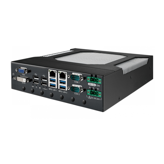
Page 22: Front Panel I/O Functions
2.2 Front Panel I/O Functions In Vecow VCM-1000 series family, all I/O connectors are located on front panel. Most of the general connections to computer device, such as USB, LAN Jack, VGA, DVI-D, DIO Port and Serial ports, are placed on the front panel. - Page 23 It is a hardware reset switch. Use this switch to reset the system without power off the system. Press the Reset Switch for a few seconds, then reset will be enabled. ©Vecow VCM-1000 User Manual GETTING TO KNOW YOUR VCM-1000...
- Page 24 Yellow-HDD LED: A hard disk LED. If the LED is on, it indicates that the system's storage is functional. If it is off, it indicates that the system's storage is not functional. If it is flashing, it indicates data access activities are in progress. ©Vecow VCM-1000 User Manual GETTING TO KNOW YOUR VCM-1000...
- Page 25 COM2 is RS-232, if you want to change to RS-422 or RS-485, you can find the setting in BIOS. BIOS Setting Function RS-232 RS-422 (5-wire) COM 1 COM 2 RS-485 RS-485 w/z auto-flow control ©Vecow VCM-1000 User Manual GETTING TO KNOW YOUR VCM-1000...
- Page 26 1920 x 1200 resolution. The DVI is automatically selected according to the display device connected. You will need a DVI-D cable when connecting to a display device. ©Vecow VCM-1000 User Manual GETTING TO KNOW YOUR VCM-1000...
- Page 27 There are 4 USB 3.2 connections available supporting up to 5Gbps/10Gbps per second data rate in the front side of VCM-1000. It also compliant with the requirements of Super Speed (SS), high speed (HS), full speed (FS) and low speed (LS).
- Page 28 LAN 3 There are 4 USB 2.0 ports available supporting up to 480Mbps per second data rate in the front side of VCM-1000. They are also compliant with the requirements of high speed (HS), full speed (FS) and low speed (LS).
- Page 29 Left Solid Green Solid Orange Orange CN_LAN1 Twinkling Twinkling Twinkling Right Yellow Yellow Yellow Yellow Green/ Left Solid Green Solid Orange Orange CN_LAN2 Twinkling Twinkling Twinkling Right Yellow Yellow Yellow Yellow ©Vecow VCM-1000 User Manual GETTING TO KNOW YOUR VCM-1000...
- Page 30 LAN 4 LAN 3 There are 4 RJ45 connectors in the front side of VCM-1000. It supports IEEE 802.3at (PoE+) Power over Ethernet (PoE) connection delivering up to 37W/54V per port and 1000BASE-T gigabit data signals over standard Ethernet Cat 5/Cat 6 cable.
- Page 31 LED Color POE Status LED 1 - 4 Solid Green POE ON Each LAN port is supported by standard RJ-45 connector with LED indicators to present Active/Link/Speed status of the connection. ©Vecow VCM-1000 User Manual GETTING TO KNOW YOUR VCM-1000...
- Page 32 • 4242-VPK Basic Isolation per DIN V VDE V 0884-10 and DIN EN 61010-1 • 3-KVRMS Isolation for 1 minute per UL 1577 • CSA Component Acceptance Notice 5A, IEC 60950-1 and IEC 61010-1 End Equipment Standards • GB4943.1-2011 CQC Certified ©Vecow VCM-1000 User Manual GETTING TO KNOW YOUR VCM-1000...
- Page 33 SIO_GPO75 EXT_OUT6 SIO_GPO76 EXT_OUT7 SIO_GPO77 EXT_OUT8 SIO_GPO80 EXT_OUT9 SIO_GPO81 EXT_OUT10 SIO_GPO82 EXT_OUT11 SIO_GPO83 EXT_OUT12 SIO_GPO84 EXT_OUT13 SIO_GPO85 EXT_OUT14 SIO_GPO86 EXT_OUT15 SIO_GPO87 +VDIO_EXT Notice: +VDIO_EXT is external 6-40VDC (NPN) or external 6-48VDC(PNP). ©Vecow VCM-1000 User Manual GETTING TO KNOW YOUR VCM-1000...
- Page 34 DO Signal circuit in SINK mode (NPN) Source (PNP) DIO_VDC LOAD 7.2K ISOLATION 6-40V (300mA) 1.5K GNDI GNDO GNDO Internal Circuit External Device GNDO DO Signal circuit in source mode (PNp) ©Vecow VCM-1000 User Manual GETTING TO KNOW YOUR VCM-1000...
- Page 35 SIO_GPO92 SIO_GPO72 SIO_GPO93 SIO_GPO73 SIO_GPO94 SIO_GPO74 SIO_GPO95 SIO_GPO75 SIO_GPO96 SIO_GPO76 SIO_GPO97 SIO_GPO77 SIO_GPI63 SIO_GPO80 SIO_GPI64 SIO_GPO81 SIO_GPI65 SIO_GPO82 SIO_GPI66 SIO_GPO83 SIO_GPO84 SIO_GP60 (Reserve) SIO_GPO85 SIO_GP61 (Reserve) SIO_GPO86 ------ SIO_GPO87 ------ ------ ©Vecow VCM-1000 User Manual GETTING TO KNOW YOUR VCM-1000...
- Page 36 There are 4 USB 3.2 connections available supporting up to 5Gbps per second data rate in the front side of VCM-1000. It also compliant with the requirements of Super Speed (SS), high speed (HS), full speed (FS) and low speed (LS).
-
Page 37: Main Board Expansion Connectors
2.3 Main Board Expansion Connectors 2.3.1 Top View (Component Side) of VCM-1000 Main Board With Connector Location CPU_FAN1 CPU_FAN1 M2B_MH2 CPU_MH1 CPU_MH2 CPU1 M2B_MH1 CPU1 DDR5_A1 DDR5_A2 CPU_MH3 CPU_MH4 PCH1 USB3_LAN1 USB3_LAN2 COM1_2 DCIN_CN1 DVI_VGA1 DCIN_CN1 USB2_1 USB2_2 PWR_BTN1 ©Vecow VCM-1000 User Manual... - Page 38 2.3.2 Bottom View (Solder Side) of VCM-1000 Main Board With Connector Location M2M_MH1 SYS_FAN1 JUSB2 SYS_FAN1 JUSB1 JUSBPWR1 HWIGN_SW1 JIGNMODE1 JIGN_FW1 M2B_SIM1 JIGN_FW1 M2B_SIM1 JUSB1 M2B_CN1 COM12_SW1 JDEBUG1 M2B_CN1 BIOS_CN2 M2M_CN1 JCMOS1 BAT1 M2E_MH1 JPOE_PWR1 B2B_IO_CN1 IO_MH1 B2B_IO_CN1 IO_MH2 IO_MH3...
- Page 39 JCMOS1 BAT1 M2E_MH1 JPOE_PWR1 IO_MH1 There are 2 onboard high performance Serial ATA III (SATA III) on VCM-1000. It B2B_IO_CN1 supports higher storage capacity with less cabling effort and smaller required space. IO_MH2 IO_MH3 The pin assignments of SATA1 and SATA2 are listed in the following table : IO_MH4 Pin No.
- Page 40 M2B_SIM1 JUSB1 M2B_CN1 COM12_SW1 JDEBUG1 The vcm-1000 also equip with a SATA power connector. The one port supports JCMOS1 5V (Up to 2A) and 12V (Up to 2A) current to the hard drive or SSD. The pin BAT1 M2E_MH1 JPOE_PWR1...
- Page 41 2.3.8 BIOS_CN1 : BIOS Socket JUSB1 M2B_CN1 COM12_SW1 JDEBUG1 BIOS_CN2 JCMOS1 BAT1 M2E_MH1 JPOE_PWR1 If the BIOS needs to be changed, please contact the Vecow RMA service team. IO_MH1 B2B_IO_CN1 IO_MH2 IO_MH3 IO_MH4 ©Vecow VCM-1000 User Manual GETTING TO KNOW YOUR VCM-1000 RST_SW1 M2B_LED1...
- Page 42 The system’s provide a ESPI Port 80 Header for Debug Card. B2B_IO_CN1 IO_MH2 IO_MH3 Pin No. Definition Pin No. Definition IO_MH4 +V3.3S Port 80_ESPI_CS# Port 80_ESPI_IO0 Port 80_ESPI_IO1 Port 80_ESPI_IO2 Port 80_ESPI_IO3 RST_SW1 M2B_LED1 M2E_LED1 HDD_LED1 PWR_LED1 Port 80_ESPI_CLK RST 80_ESPI_RST# ©Vecow VCM-1000 User Manual GETTING TO KNOW YOUR VCM-1000...
- Page 43 JCMOS1 BAT1 M2E_MH1 JPOE_PWR1 IO_MH1 The VCM-1000's real-time clock is powered by a lithium battery. It is equipped with B2B_IO_CN1 Panasonic BR2032 190mAh lithium battery. It is recommended that you not replace the IO_MH2 IO_MH3 lithium battery on your own, but if the battery needs to be changed, please contact the IO_MH4 Vecow RMA service team.
- Page 44 M.2 key M connector is suitable for applications that use Host I/Fs supported by either PCIe B2B_IO_CN1 Module card , and NVMe or SATA SSD that types include 22110 (2280 with iron sheet). IO_MH2 IO_MH3 IO_MH4 RST_SW1 M2B_LED1 M2E_LED1 HDD_LED1 PWR_LED1 ©Vecow VCM-1000 User Manual GETTING TO KNOW YOUR VCM-1000...
- Page 45 The Mini SIM card socket is support locked type. Please make sure to unplug the system BAT1 M2E_MH1 power before inserting the Mini SIM card. JPOE_PWR1 IO_MH1 B2B_IO_CN1 IO_MH2 IO_MH3 IO_MH4 RST_SW1 M2B_LED1 M2E_LED1 HDD_LED1 PWR_LED1 ©Vecow VCM-1000 User Manual GETTING TO KNOW YOUR VCM-1000...
-
Page 46: Main Board Jumper Settings
You may configure your card to match the needs of your application by DIP switch. As below show the DIP switch on and off. 1 : OFF 1 : ON 1 : ON 2 : OFF 2 : OFF 2 : ON ©Vecow VCM-1000 User Manual GETTING TO KNOW YOUR VCM-1000... - Page 47 LAN 2 DC-IN 24V IO_MH4 WLAN Isolated LAN 6 LAN 5 LAN 4 LAN 3 RST_SW1 M2B_LED1 M2E_LED1 HDD_LED1 PWR_LED1 Location Description Function Supported Wake Up(Default) JSBPWR1 Non Wake Up support ©Vecow VCM-1000 User Manual GETTING TO KNOW YOUR VCM-1000...
- Page 48 1 - 2 Normal (Default) JCMOS1 2 - 3 Clear CMOS Enable security measures defined in the Flash Descriptor. (Default) RST_SW1 JHDA_ M2B_LED1 M2E_LED1 HDD_LED1 PWR_LED1 SDO1 Disable Flash Descriptor Security (Flash ME) ©Vecow VCM-1000 User Manual GETTING TO KNOW YOUR VCM-1000...
- Page 49 DCD / RXD Termination 120R Enable COM1 1(OFF) DCD / RXD Termination 120R Disable(default) COM12_ RST_SW1 M2B_LED1 M2E_LED1 HDD_LED1 PWR_LED1 2(ON) DCD / RXD Termination 120R Enable COM2 2(OFF) DCD / RXD Termination 120R Disable(default) ©Vecow VCM-1000 User Manual GETTING TO KNOW YOUR VCM-1000...
-
Page 50: Ignition Control
2.5.1 Adjust Ignition Control Modes VCM-1000 series provides 16 modes of different power on/off delay periods adjustable via HWIGN_SW1 switch. The default rotary switch is set to 0 in ATX/AT power mode. HWIGN_SW1 : Ignition Control... - Page 51 5 seconds 60 seconds 5 seconds 90 seconds 5 seconds 120 seconds 10 seconds 10 seconds 10 seconds 30 seconds 10 seconds 60 seconds 10 seconds 90 seconds 10 seconds 120 seconds ©Vecow VCM-1000 User Manual GETTING TO KNOW YOUR VCM-1000...
- Page 52 Note : 1. DC power source and IGN share the same ground. 2. VCM-1000 supports 24V DC power input in ATX/AT mode. In Ignition mode, the input voltage is fixed to 12V/24V for car battery scenario. 3. For proper ignition control, the power button setting should be “Power Down” mode.
-
Page 53: Chapter 3 System Setup
SYSTEM SETUP 3.1 How to Open Your VCM-1000 3.1.1 VCM-1000 / VCM-1000F Step 1 Remove bottom side four flat head M3x4L screws both side four flat head M3x4L screws, and take out bottom cover. Step 2 After take out bottom cover. - Page 54 3.1.2 VCM-1100F Step 1 Remove front and rear four flat head M3x4L screws both side four flat head M3x4L screws, and take out bottom cover. Step 2 After take out bottom cover. ©Vecow VCM-1000 User Manual SYSTEM SETUP...
-
Page 55: Installing Cpu
3.2 Installing CPU 3.2.1 VCM-1000 Step 1 Remove two pan head M3x4L screws, and take out sink cover. Step 2 Remove three I head M3x6L screws, and take out heat sink. ©Vecow VCM-1000 User Manual SYSTEM SETUP... - Page 56 Step 3 CPU slot. Step 4 Remove CPU mylar. ©Vecow VCM-1000 User Manual SYSTEM SETUP...
- Page 57 Step 5 Open CPU independent loading mechanism (ILM) Step 6 Install CPU. (Be careful CPU pin). Step 7 Close CPU independent loading Mechanism (ILM) and finish. ©Vecow VCM-1000 User Manual SYSTEM SETUP...
- Page 58 3.2.2 VCM-1000F/VCM-1100F Step 1 Remove two pan head M3x4L screws, and take out fan cover. Step 2 Remove three I head M3x6L screws, fan header and take out heat sink. ©Vecow VCM-1000 User Manual SYSTEM SETUP...
- Page 59 Step 3 CPU slot. Step 4 Remove CPU mylar. ©Vecow VCM-1000 User Manual SYSTEM SETUP...
- Page 60 Step 5 Open CPU independent loading mechanism (ILM) Step 6 Install CPU. (Be careful CPU pin). Step 7 Close CPU independent loading Mechanism (ILM) and finish. ©Vecow VCM-1000 User Manual SYSTEM SETUP...
-
Page 61: Installing Ddr5 So-Dimm Modules
3.3 Installing DDR5 SO-DIMM Modules Step 1 DDR5 SO-DIMM slot. Step 2 Install DDR5 RAM module into SO-DIMM socket. ©Vecow VCM-1000 User Manual SYSTEM SETUP... - Page 62 Step 3 Make sure RAM module is locked by the memory slot. ©Vecow VCM-1000 User Manual SYSTEM SETUP...
-
Page 63: Installing Mini Pcie Card
3.4 Installing Mini PCIe Card Step 1 SIM slot. Step 2 Push SIM card slot cover open and install SIM card. ©Vecow VCM-1000 User Manual SYSTEM SETUP... - Page 64 Step 3 Close the cover. ©Vecow VCM-1000 User Manual SYSTEM SETUP...
-
Page 65: Installing Ssd/Hdd
3.5 Installing SSD/HDD 3.5.1 VCM-1000/VCM-1000F Step 1 SSD/HDD bracket for VCM-1000/VCM-1000F. Step 2 Put SSD/HDD into bracket and fasten four flat head M3x4L screws. ©Vecow VCM-1000 User Manual SYSTEM SETUP... - Page 66 Step 3 Connector SATA data, SATA power cable to SSD/HDD and fasten four pan head M3x4L screws. 3.5.2 VCM-1100F Step 1 SSD/HDD bracket for VCM-1100F. ©Vecow VCM-1000 User Manual SYSTEM SETUP...
- Page 67 Step 2 Put SSD/HDD into bracket and fasten eithgt flat head M3x4L screws. (Four on the bottom, four on the side.) Step 3 Connector SATA data, SATA power cable to SSD/HDD and fasten four pan head M3x4L screws. ©Vecow VCM-1000 User Manual SYSTEM SETUP...
-
Page 68: Installing
3.6.1 M.2 Key E 2230 Install M.2 Key E 2230 into slot and fasten one pan head M3x4L screw. 3.6.2 M.2 Key B 2242/3042 Install M.2 Key B 2242/3042 into slot and fasten one pan head M3x4L screw. ©Vecow VCM-1000 User Manual SYSTEM SETUP... - Page 69 3.6.3 M.2 Key B 3052 Step 1 Change the stud position. Step 2 M.2 extender bracket to 2280 slot. (Brack off excess size.) ©Vecow VCM-1000 User Manual SYSTEM SETUP...
- Page 70 Step 3 Install M.2 key b 3052 module on extender bracket and fasten one pan head M3x4L screw. Step 4 Install M.2 Key B 3052 with extender bracket into slot and fasten one pan head M3x4L screw. ©Vecow VCM-1000 User Manual SYSTEM SETUP...
- Page 71 3.6.4 M.2 Key B 2280 Step 1 Change the stud position. Step 2 Install M.2 Key B 2280 into slot and fasten one pan head M3x4L screw. ©Vecow VCM-1000 User Manual SYSTEM SETUP...
- Page 72 M.2 Key B 22110 into slot and fasten one pan head M3x4L screw. 3.6.6 M.2 Key M 2280 Step 1 Install M.2 key M 2280 module on extender bracket and fasten one pan head M3x4L screw. ©Vecow VCM-1000 User Manual SYSTEM SETUP...
- Page 73 Step 2 Install M.2 Key B 2280 with extender bracket into slot and fasten one pan head M3x4L screw.. ©Vecow VCM-1000 User Manual SYSTEM SETUP...
-
Page 74: Installing Antenna Cable
3.7 Installing Antenna Cable Step 1 Remove the rubber corks on the panel. VCM-1000/VCM-1000F VCM-1100F Step 2 Put antenna cable connector into the hole on panel. ©Vecow VCM-1000 User Manual SYSTEM SETUP... - Page 75 Step 3 Fasten washer on the antenna cable connector. ©Vecow VCM-1000 User Manual SYSTEM SETUP...
-
Page 76: Mount Your Vcm-1000
3.8 Mount Your VCM-1000 3.8.1 Wall mount Fasten six flat head #6-32x6L screws. 3.8.2 VESA mount Fasten six flat head #6-32x6L screws. ©Vecow VCM-1000 User Manual SYSTEM SETUP... - Page 77 3.8.3 Din rail mount Fasten six flat head #6-32x6L screws. ©Vecow VCM-1000 User Manual SYSTEM SETUP...
-
Page 78: Chapter 4 Bios Setup
Figure 4-1 : Entering Setup Screen BIOS provides an interface for users to check and change system configuration. The BIOS setup program is accessed by pressing the <Del> key when POST display output is shown. ©Vecow VCM-1000 User Manual BIOS SETUP... -
Page 79: Main Menu
Set the Date. Use Tab to switch between Date elements. Default Ranges: Year: 1998-9999 Months: 1-12 Days: Dependent on month Range of Years may vary. System Time Set the Time. Use Tab to switch between Time elements. ©Vecow VCM-1000 User Manual BIOS SETUP... -
Page 80: Advanced Functions
4.3 Advanced Functions Figure 4-3 : BIOS Advanced Menu Select advanced tab to enter advanced BIOS setup options, such as CPU configuration, ACPI settings, and Super IO configuration. 4.3.1 CPU Configuration Figure 4-3-1 : CPU Configuration ©Vecow VCM-1000 User Manual BIOS SETUP... - Page 81 Cores and E-cores are looked at together. When both are {0,0}, Pcode will enable all cores. Hyper-Threading Enable or Disable Hyper-Threading Technology. Enable/Disable AES (Advanced Encryption Standard). 4.3.2 PCH-FW Configuration Figure 4 3-2: PCH-FW Configuration PTT Configuration Configure PTT. ©Vecow VCM-1000 User Manual BIOS SETUP...
- Page 82 Disables PTT is SkuMgr Warning! PTT/dTPM will be disabled and all data saved on it will be lost. 4.3.3 Trusted Computing Figure 4 3-3: Trusted Computing Control the TPM device status and display related information if TPM chip is present. ©Vecow VCM-1000 User Manual BIOS SETUP...
- Page 83 Figure 4-3-5-1: Serial Port X Configuration Serial Port Enable or Disable Serial Port (COM). Device Mode Select Device Mode. PPS Mode Enable or Disable PPS. High Speed Mode Enable or Disable Serial Port High Speed. (Serial Port 1 only). ©Vecow VCM-1000 User Manual BIOS SETUP...
- Page 84 Fan full speed temperature limit Fan will full speed when temperature higher than this limit. Fan start PWM Fan will start with this PWM value. Manual PWM Setting Fan will work with this Manual PWM Value. ©Vecow VCM-1000 User Manual BIOS SETUP...
- Page 85 Wait time in seconds to press ESC key to abort the PXE boot. Use either +/- or numeric keys to set the value. Media detect count Number of times the presence of media will be checked. Use either +/- or numeric keys to set the value. ©Vecow VCM-1000 User Manual BIOS SETUP...
-
Page 86: Chipset Functions
(SA) Configuration, PCH-IO Configuration, and SW Ignition Configuration. 4.4.1 System Agent (SA) Configuration Figure 4-4-1: System Agent (SA) Configuration Above 4GB MMIO BIOS assignment Enable/Disable above 4GB MemoryMappedIO BIOS assignment This is enabled automatically when Aperture Size is set to 2048MB. ©Vecow VCM-1000 User Manual BIOS SETUP... - Page 87 GTT Size Select the GTT Size. Aperture Size Select the Aperture Size. Note : Above 4GB MMIO BIOS assignment is automatically enabled when selecting > 2048MB aperture. To use this feature, please disable CSM Support. ©Vecow VCM-1000 User Manual BIOS SETUP...
- Page 88 Specify what state to go to when power is re-applied after a power failure (G3 state). 4.4.2.1 SATA Configuration Figure 4-4-2-1: SATA Configuration SATA Controller(s) Enable/Disable SATA Device. 4.4.3 Module Management Figure 4-4-3: Module Management M2B_CN1 Type Select M2B_CN1 Type. ©Vecow VCM-1000 User Manual BIOS SETUP...
-
Page 89: Security Function
The delay time after user trigger ignition off signal (Seconds). Force Shutdown Timer (Minutes) Used to force cut off system power when OS unable gracefully shutdown system successfully. 4.5 Security Function Figure 4-5 : BIOS Security Menu Administrator Password Set Administrator Password. ©Vecow VCM-1000 User Manual BIOS SETUP... - Page 90 Discard or Save changes option in setup does not have any impact on HDD when password is set or removed. If the 'Set HDD User Password' option is hidden, do power cycle to enable the option again. Set Master Password Set Master Password. ©Vecow VCM-1000 User Manual BIOS SETUP...
- Page 91 Force System to User Mode. Install factory default Secure Boot key databases Reset To Setup Mode Delete all Secure Boot key databases from NVRAM. Key Management Enables expert users to modify Secure Boot Policy variables without variable authentication. ©Vecow VCM-1000 User Manual BIOS SETUP...
-
Page 92: Boot Function
Figure 4-7: Bios Save and Exit Menu Save Changes Reset Reset the system after saving the changes. Discard Changes and Reset Reset system setup without saving any changes. Restore Defaults Restore/Load Default values for all the setup options. ©Vecow VCM-1000 User Manual BIOS SETUP... -
Page 93: Appendix A : Isolated Dio Guide
APPENDIX A : Isolated DIO Guide A.1 Function Description The VCM-1000 offers a 24bit DO/ 4bit DI (Isolated) 40-pin terminal block connector, a watchdog timer, and a 4-port POE. Isolated DIO pins are fixed by Hardware design that cannot change in/out direction in runtime process. - Page 94 SIO_GP61 (Reserve) SIO_GPO86 ------ SIO_GPO87 ------ ------ POE definition is shown below : LAN 6 LAN 5 LAN 4 LAN 3 Port No. Definition Port No. Definition POE 1 POE 3 POE 2 POE 4 ©Vecow VCM-1000 User Manual Appendix A...
- Page 95 DIO Connector (NPN, Default) 6-48V DC DIO_VDC (Pin 20) DO (Pin 11-18) DIO_GND (Pin 10, 19) Source Mode Device DIO Connector (PNP) 6-48V DC DIO_VDC (Pin 20) DO (Pin 11-18) DIO_GND (Pin 10, 19) ©Vecow VCM-1000 User Manual Appendix A...
- Page 96 Manual folder include API description. Sample folder include sample program, driver library, and API library for Windows/Linux Source folder include sample program source code that compile on Visual Studio 2008/ubuntu16.04. A.4 Sample Execute demo tool. Windows Linux ©Vecow VCM-1000 User Manual Appendix A...
- Page 97 Vecow_DIO_VCM Vecow_POE_VCM Vecow_WDT ©Vecow VCM-1000 User Manual Appendix A...
-
Page 98: Appendix B : Software Functions
APPENDIX B : Software Functions B.1 Driver API Guide In Header folder, Vecow.h and VecowLinux.h contain usabled API for Windows/Linux. BOOL initial_SIO(BYTE Isolate_Type, BYTE DIO_NPN) Initial machine for IO and watch dogtimer. Isolate_Type : DIO type. 1 : Isolated DIO;... - Page 99 DO ([23:0]) : Output state, pin setting by hexadecimal bitmask. 1 : High; 0 : Low. Return : TRUE (1) : Success. FALSE (0) : Fail (Initial error or hardware problem). 1 : High; 0 : Low. ©Vecow VCM-1000 User Manual Appendix B...
- Page 100 Mask ([3:0]) : DC Enable/Disable, pin setting by hexadecimal bitmask. 1 : Enable; 0 : Disable. Return : TRUE (1) : Success. FALSE (0) : Fail (Initial error, or out of range error, or call by pointer error, or hardware problem) ©Vecow VCM-1000 User Manual Appendix B...
- Page 101 POE ([3:0]) : POE state, pin setting by hexadecimal bitmask. 1 : On; 0 : Off. Return : TRUE (1) : Success. FALSE (0) : Fail (Initial error, or out of range error, or call by pointer error, or hardware problem). ©Vecow VCM-1000 User Manual Appendix B...
-
Page 102: Appendix C : Power Consumption (Vcm-1100)
LAN 3 (i350) 1.0 Gbps LAN 4 (i350) 1.0 Gbps LAN 5 (i350) 1.0 Gbps LAN 6 (i350) 1.0 Gbps Graphics Output Power Plan Balance (Windows10 Power plan) Power Source Chroma 62006P-100-25 Test Program BurnInTest ©Vecow VCM-1000 User Manual Appendix C... - Page 103 Power on and boot to Win10 (64-bit) Run 100% CPU Run 100% CPU Power usage with 2D usage with 3D Input Current Consumption Current Consumption ® Intel Core™ i9- 2.439A 58.53W 3.462A 83.09W 13900E ©Vecow VCM-1000 User Manual Appendix C...
- Page 104 Power on and boot to Win10 (64-bit) Run 100% CPU Run 100% CPU Power usage with 2D usage with 3D Input Current Consumption Current Consumption ® Intel Core™ i7- 1.888A 45.32W 2.233A 53.58W 13700TE ©Vecow VCM-1000 User Manual Appendix C...
-
Page 105: Appendix D : Power Consumption (Vcm-1000)
SATA 0 Innodisk DGS25-64GD81BC1QC 64GB SATA 1 Transcend TS128GSSD230S 128GB LAN 1 (i219-V) 1.0 Gbps LAN 2 (i210) 1.0 Gbps Graphics Output Power Plan Balance (Windows10 Power plan) Power Source Chroma 62006P-100-25 Test Program BurnInTest ©Vecow VCM-1000 User Manual Appendix D... - Page 106 Power on and boot to Win10 (64-bit) Run 100% CPU Run 100% CPU Power usage with 2D usage with 3D Input Current Consumption Current Consumption ® Intel Core™ i7- 1.557A 37.37W 2.105A 50.51W 13700TE ©Vecow VCM-1000 User Manual Appendix D...
-
Page 107: Appendix E : Supported Memory & Storage List
*1(DIMM 1) PASS PASS PASS *1(DIMM 2) PASS PASS PASS E.2 Supported Non-ECC Memory List Test Temp. Brand Info (Celsius) SMART 32G DDR5 4800 SO-DIMM SR4G6SO5285-SB 25ºC SLLINK 32G DDR5 4800 SO-DIMM J5BGSH2G8A4FC 25ºC ©Vecow VCM-1000 User Manual Appendix E... - Page 108 DGS25-64GD81BC1QC Toshiba KXG50ZNV512G 512GB Kingston SA2000MB 250GB 970 EVO PLUS M.2 PCIe 250GB MZ-V7S250 SAMSUNG 980 EVO PRO 250GB MZ-V8P250BW SMART FDMP8960GTCXA111 960GB ** If more help is needed, please contact Vecow Technical Support.** ©Vecow VCM-1000 User Manual Appendix E...
- Page 109 No part of this publication may be reproduced in any form or by any means, electric, photocopying, or recording, without prior authorization from the publisher. The rights of all the brand names, product names, and trademarks belong to their respective owners. © Vecow Co., Ltd. 2023. All rights reserved.
Need help?
Do you have a question about the VCM-1000 and is the answer not in the manual?
Questions and answers