
Related Manuals for Vecow RCX-1000


Summary of Contents for Vecow RCX-1000
- Page 1 USER USER RCX-1000 Manual Manual Intel ® Xeon ® /Core™ i7/i5/i3 Expandable Robust Computing System Workstation-grade, Flexible, Fanless, Extended Temperature 1.1.0 Edition 20190418...
- Page 2 Record of Revision Version Date Remark Page Description 0.10 2019/03/26 Preliminary Release 1.00 2019/04/17 Official Release 2019/04/18 48, 49 Update ©Vecow RCX-1000 User Manual...
- Page 3 This manual is released by Vecow Co., Ltd. for reference purpose only. All product offerings and specifications are subject to change without prior notice. It does not represent commitment of Vecow Co., Ltd. Vecow shall not be liable for direct, indirect, special, incidental, or consequential damages arising out of the use of the product or documentation or any infringements upon the rights of third parties, which may result from such use.
- Page 4 RCX-1430FR 1 PCIe x4, 1 PCIe x1, 4 COM, 6 USB 3.0, 2 SIM, 32 Isolated DIO RCX-1000, 2 GigE LAN, 1 PCIe x16, 1 PCIe x4, 1 PCIe x1, 4 COM, RCX-1430F 6 USB 3.0, 2 SIM, 32 Isolated DIO...
- Page 5 600W, 24V, 90V AC to 305V AC Power Supply 600W, 28.8V, 90V AC to 305V AC Power Supply, Wide PWS-600W-WT Temperature -40°C to +70°C FAN Module Fan Module for RCX-1000 Series FAN Sink Fan Sink for RCX-1000 Series PCIE HOLD-DOWN Kit Hold Down Module for PCIe Card TMK2-20P-100...
-
Page 6: Table Of Contents
1.3.20 Specifications of RCX-1412FR RTX2080 1.3.21 Specifications of RCX-1412F RTX2080 1.4 Supported CPU List 1.5 Mechanical Dimension 1.5.1 Dimensions of RCX-1400FR/RCX-1000FR RTX 1.5.2 Dimensions of RCX-1400F/RCX-1000F RTX 1.5.3 Dimensions of RCX-1440R/RCX-1422R/RCX-1404R 1.5.4 Dimensions of RCX-1440/RCX-1422/RCX-1404 1.5.5 Dimensions of RCX-1220A/RCX-1220/RCX-1211 ©Vecow RCX-1000 User Manual... - Page 7 CHAPTER 2 GETTING TO KNOW YOUR RCX-1000 2.1 Packing List 2.2 Front Panel I/O Functions 2.3 Main Board Expansion Connectors 2.4 Main Board Jumper Settings 2.5 Ignition Control CHAPTER 3 SYSTEM SETUP 3.1 How to open your RCX-1000 3.2 Installing CPU 3.3 Installing DDR4 SO-DIMM Modules...
- Page 8 APPENDIX A : Isolated DIO Guide APPENDIX B : Software Functions APPENDIX C : RAID Functions APPENDIX D : Power Consumption APPENDIX E : Supported Memory & Storage List APPENDIX F : How to Install Power Supply ©Vecow RCX-1000 User Manual viii...
-
Page 9: Chapter 1 General Introduction
GENERAL INTRODUCTION 1.1 Overview RCX-1000 is a high-performance, flexible and rugged computing engine for AIoT and Industry 4.0 applications. LGA1151 Socket supports 6-core 8th ® ® Generation Intel Xeon /Core™ i7/i5/i3 processor (Coffee Lake-S) running with ® workstation-grade Intel C246 chipset; 4 SO-DIMM support dual channel DDR4 ®... -
Page 10: Features
AI computing (RCX-1000 RTX Series only) • 7 displays : 1 DVI, 1 HDMI, and 5 DisplayPort, up to 8K resolution (RCX-1000 RTX Series only) • 2 independent GigE LAN, iAMT 12.0 supported •... -
Page 11: Product Specification
• 1 M.2 Key M Socket Audio Audio Codec Realtek ALC892, 5.1 Channel HD Audio Audio Interface 1 Mic-in, 1 Line-out Ethernet ® LAN 1 Intel I219LM Gigabit LAN supports iAMT 12.0 LAN 2 Intel ® I210 Gigabit LAN ©Vecow RCX-1000 User Manual GENERAL INTRODUCTION... - Page 12 5% to 95% humidity, non-condensing Relative Humidity 95% at 75°C • IEC 60068-2-27 Shock • SSD : 50G @wallmount, Half-sine, 11ms • IEC 60068-2-64 Vibration • SSD : 5Grms, 5Hz to 500Hz, 3 Axis CE, FCC, EN50155, EN50121-3-2 ©Vecow RCX-1000 User Manual GENERAL INTRODUCTION...
-
Page 13: Specifications Of Rcx-1430F
• 1 M.2 Key M Socket Audio Audio Codec Realtek ALC892, 5.1 Channel HD Audio Audio Interface 1 Mic-in, 1 Line-out Ethernet ® LAN 1 Intel I219LM Gigabit LAN supports iAMT 12.0 ® LAN 2 Intel I210 Gigabit LAN ©Vecow RCX-1000 User Manual GENERAL INTRODUCTION... - Page 14 5% to 95% humidity, non-condensing Relative Humidity 95% at 75°C • IEC 60068-2-27 Shock • SSD : 50G @wallmount, Half-sine, 11ms • IEC 60068-2-64 Vibration • SSD : 5Grms, 5Hz to 500Hz, 3 Axis CE, FCC, EN50155, EN50121-3-2 ©Vecow RCX-1000 User Manual GENERAL INTRODUCTION...
-
Page 15: Specifications Of Rcx-1421Fr
• 1 M.2 Key M Socket Audio Audio Codec Realtek ALC892, 5.1 Channel HD Audio Audio Interface 1 Mic-in, 1 Line-out Ethernet ® LAN 1 Intel I219LM Gigabit LAN supports iAMT 12.0 ® LAN 2 Intel I210 Gigabit LAN ©Vecow RCX-1000 User Manual GENERAL INTRODUCTION... - Page 16 5% to 95% humidity, non-condensing Relative Humidity 95% at 75°C • IEC 60068-2-27 Shock • SSD : 50G @wallmount, Half-sine, 11ms • IEC 60068-2-64 Vibration • SSD : 5Grms, 5Hz to 500Hz, 3 Axis CE, FCC, EN50155, EN50121-3-2 ©Vecow RCX-1000 User Manual GENERAL INTRODUCTION...
-
Page 17: Specifications Of Rcx-1421F
• 1 M.2 Key M Socket Audio Audio Codec Realtek ALC892, 5.1 Channel HD Audio Audio Interface 1 Mic-in, 1 Line-out Ethernet ® LAN 1 Intel I219LM Gigabit LAN supports iAMT 12.0 ® LAN 2 Intel I210 Gigabit LAN ©Vecow RCX-1000 User Manual GENERAL INTRODUCTION... - Page 18 5% to 95% humidity, non-condensing Relative Humidity 95% at 75°C • IEC 60068-2-27 Shock • SSD : 50G @wallmount, Half-sine, 11ms • IEC 60068-2-64 Vibration • SSD : 5Grms, 5Hz to 500Hz, 3 Axis CE, FCC, EN50155, EN50121-3-2 ©Vecow RCX-1000 User Manual GENERAL INTRODUCTION...
-
Page 19: Specifications Of Rcx-1412Fr
• 1 M.2 Key M Socket Audio Audio Codec Realtek ALC892, 5.1 Channel HD Audio Audio Interface 1 Mic-in, 1 Line-out Ethernet ® LAN 1 Intel I219LM Gigabit LAN supports iAMT 12.0 ® LAN 2 Intel I210 Gigabit LAN ©Vecow RCX-1000 User Manual GENERAL INTRODUCTION... - Page 20 5% to 95% humidity, non-condensing Relative Humidity 95% at 75°C • IEC 60068-2-27 Shock • SSD : 50G @wallmount, Half-sine, 11ms • IEC 60068-2-64 Vibration • SSD : 5Grms, 5Hz to 500Hz, 3 Axis CE, FCC, EN50155, EN50121-3-2 ©Vecow RCX-1000 User Manual GENERAL INTRODUCTION...
-
Page 21: Specifications Of Rcx-1412F
• 1 M.2 Key M Socket Audio Audio Codec Realtek ALC892, 5.1 Channel HD Audio Audio Interface 1 Mic-in, 1 Line-out Ethernet ® LAN 1 Intel I219LM Gigabit LAN supports iAMT 12.0 ® LAN 2 Intel I210 Gigabit LAN ©Vecow RCX-1000 User Manual GENERAL INTRODUCTION... - Page 22 5% to 95% humidity, non-condensing Relative Humidity 95% at 75°C • IEC 60068-2-27 Shock • SSD : 50G @wallmount, Half-sine, 11ms • IEC 60068-2-64 Vibration • SSD : 5Grms, 5Hz to 500Hz, 3 Axis CE, FCC, EN50155, EN50121-3-2 ©Vecow RCX-1000 User Manual GENERAL INTRODUCTION...
-
Page 23: Specifications Of Rcx-1440R
• 1 M.2 Key M Socket Audio Audio Codec Realtek ALC892, 5.1 Channel HD Audio Audio Interface 1 Mic-in, 1 Line-out Ethernet ® LAN 1 Intel I219LM Gigabit LAN supports iAMT 12.0 ® LAN 2 Intel I210 Gigabit LAN ©Vecow RCX-1000 User Manual GENERAL INTRODUCTION... - Page 24 5% to 95% humidity, non-condensing Relative Humidity 95% at 75°C Shock • IEC 60068-2-27 • SSD : 50G @wallmount, Half-sine, 11ms Vibration • IEC 60068-2-64 • SSD : 5Grms, 5Hz to 500Hz, 3 Axis CE, FCC, EN50155, EN50121-3-2 ©Vecow RCX-1000 User Manual GENERAL INTRODUCTION...
-
Page 25: Specifications Of Rcx-1440
• 1 M.2 Key M Socket Audio Audio Codec Realtek ALC892, 5.1 Channel HD Audio Audio Interface 1 Mic-in, 1 Line-out Ethernet ® LAN 1 Intel I219LM Gigabit LAN supports iAMT 12.0 ® LAN 2 Intel I210 Gigabit LAN ©Vecow RCX-1000 User Manual GENERAL INTRODUCTION... - Page 26 5% to 95% humidity, non-condensing Relative Humidity 95% at 75°C • IEC 60068-2-27 Shock • SSD : 50G @wallmount, Half-sine, 11ms • IEC 60068-2-64 Vibration • SSD : 5Grms, 5Hz to 500Hz, 3 Axis CE, FCC, EN50155, EN50121-3-2 ©Vecow RCX-1000 User Manual GENERAL INTRODUCTION...
-
Page 27: Specifications Of Rcx-1422R
• 1 M.2 Key M Socket Audio Audio Codec Realtek ALC892, 5.1 Channel HD Audio Audio Interface 1 Mic-in, 1 Line-out Ethernet ® LAN 1 Intel I219LM Gigabit LAN supports iAMT 12.0 ® LAN 2 Intel I210 Gigabit LAN ©Vecow RCX-1000 User Manual GENERAL INTRODUCTION... - Page 28 5% to 95% humidity, non-condensing Relative Humidity 95% at 75°C Shock • IEC 60068-2-27 • SSD : 50G @wallmount, Half-sine, 11ms Vibration • IEC 60068-2-64 • SSD : 5Grms, 5Hz to 500Hz, 3 Axis CE, FCC, EN50155, EN50121-3-2 ©Vecow RCX-1000 User Manual GENERAL INTRODUCTION...
-
Page 29: Specifications Of Rcx-1422
• 1 M.2 Key M Socket Audio Audio Codec Realtek ALC892, 5.1 Channel HD Audio Audio Interface 1 Mic-in, 1 Line-out Ethernet ® LAN 1 Intel I219LM Gigabit LAN supports iAMT 12.0 LAN 2 Intel ® I210 Gigabit LAN ©Vecow RCX-1000 User Manual GENERAL INTRODUCTION... - Page 30 5% to 95% humidity, non-condensing Relative Humidity 95% at 75°C • IEC 60068-2-27 Shock • SSD : 50G @wallmount, Half-sine, 11ms • IEC 60068-2-64 Vibration • SSD : 5Grms, 5Hz to 500Hz, 3 Axis CE, FCC, EN50155, EN50121-3-2 ©Vecow RCX-1000 User Manual GENERAL INTRODUCTION...
-
Page 31: Specifications Of Rcx-1404R
• 1 M.2 Key M Socket Audio Audio Codec Realtek ALC892, 5.1 Channel HD Audio Audio Interface 1 Mic-in, 1 Line-out Ethernet ® LAN 1 Intel I219LM Gigabit LAN supports iAMT 12.0 LAN 2 Intel ® I210 Gigabit LAN ©Vecow RCX-1000 User Manual GENERAL INTRODUCTION... - Page 32 5% to 95% humidity, non-condensing Relative Humidity 95% at 75°C • IEC 60068-2-27 Shock • SSD : 50G @wallmount, Half-sine, 11ms • IEC 60068-2-64 Vibration • SSD : 5Grms, 5Hz to 500Hz, 3 Axis CE, FCC, EN50155, EN50121-3-2 ©Vecow RCX-1000 User Manual GENERAL INTRODUCTION...
-
Page 33: Specifications Of Rcx-1404
• 1 M.2 Key M Socket Audio Audio Codec Realtek ALC892, 5.1 Channel HD Audio Audio Interface 1 Mic-in, 1 Line-out Ethernet ® LAN 1 Intel I219LM Gigabit LAN supports iAMT 12.0 LAN 2 Intel ® I210 Gigabit LAN ©Vecow RCX-1000 User Manual GENERAL INTRODUCTION... - Page 34 5% to 95% humidity, non-condensing Relative Humidity 95% at 75°C • IEC 60068-2-27 Shock • SSD : 50G @wallmount, Half-sine, 11ms • IEC 60068-2-64 Vibration • SSD : 5Grms, 5Hz to 500Hz, 3 Axis CE, FCC, EN50155, EN50121-3-2 ©Vecow RCX-1000 User Manual GENERAL INTRODUCTION...
-
Page 35: Specifications Of Rcx-1220A
• 1 M.2 Key M Socket Audio Audio Codec Realtek ALC892, 5.1 Channel HD Audio Audio Interface 1 Mic-in, 1 Line-out Ethernet ® LAN 1 Intel I219LM Gigabit LAN supports iAMT 12.0 LAN 2 Intel ® I210 Gigabit LAN ©Vecow RCX-1000 User Manual GENERAL INTRODUCTION... - Page 36 5% to 95% humidity, non-condensing Relative Humidity 95% at 75°C • IEC 60068-2-27 Shock • SSD : 50G @wallmount, Half-sine, 11ms • IEC 60068-2-64 Vibration • SSD : 5Grms, 5Hz to 500Hz, 3 Axis CE, FCC, EN50155, EN50121-3-2 ©Vecow RCX-1000 User Manual GENERAL INTRODUCTION...
-
Page 37: Specifications Of Rcx-1220
• 1 M.2 Key M Socket Audio Audio Codec Realtek ALC892, 5.1 Channel HD Audio Audio Interface 1 Mic-in, 1 Line-out Ethernet ® LAN 1 Intel I219LM Gigabit LAN supports iAMT 12.0 ® LAN 2 Intel I210 Gigabit LAN ©Vecow RCX-1000 User Manual GENERAL INTRODUCTION... - Page 38 5% to 95% humidity, non-condensing Relative Humidity 95% at 75°C • IEC 60068-2-27 Shock • SSD : 50G @wallmount, Half-sine, 11ms • IEC 60068-2-64 Vibration • SSD : 5Grms, 5Hz to 500Hz, 3 Axis CE, FCC, EN50155, EN50121-3-2 ©Vecow RCX-1000 User Manual GENERAL INTRODUCTION...
-
Page 39: Specifications Of Rcx-1211
• 1 M.2 Key M Socket Audio Audio Codec Realtek ALC892, 5.1 Channel HD Audio Audio Interface 1 Mic-in, 1 Line-out Ethernet ® LAN 1 Intel I219LM Gigabit LAN supports iAMT 12.0 ® LAN 2 Intel I210 Gigabit LAN ©Vecow RCX-1000 User Manual GENERAL INTRODUCTION... - Page 40 5% to 95% humidity, non-condensing Relative Humidity 95% at 75°C • IEC 60068-2-27 Shock • SSD : 50G @wallmount, Half-sine, 11ms • IEC 60068-2-64 Vibration • SSD : 5Grms, 5Hz to 500Hz, 3 Axis CE, FCC, EN50155, EN50121-3-2 ©Vecow RCX-1000 User Manual GENERAL INTRODUCTION...
-
Page 41: Specifications Of Rcx-1430Fr Rtx2080
2 SATA III (Mini PCIe Type, 6Gbps) • 4 Front-access 2.5" SSD/HDD Tray Storage Device • 1 M.2 Key M Socket Audio Audio Codec Realtek ALC892, 5.1 Channel HD Audio Audio Interface 1 Mic-in, 1 Line-out ©Vecow RCX-1000 User Manual GENERAL INTRODUCTION... - Page 42 5% to 95% humidity, non-condensing Relative Humidity 95% at 45°C • IEC 60068-2-27 Shock • SSD : 50G @wallmount, Half-sine, 11ms • IEC 60068-2-64 Vibration • SSD : 5Grms, 5Hz to 500Hz, 3 Axis CE, FCC, EN50155, EN50121-3-2 ©Vecow RCX-1000 User Manual GENERAL INTRODUCTION...
-
Page 43: Specifications Of Rcx-1430F Rtx2080
2 SATA III (Mini PCIe Type, 6Gbps) • 4 2.5" SSD/HDD Bracket (Internal) Storage Device • 1 M.2 Key M Socket Audio Audio Codec Realtek ALC892, 5.1 Channel HD Audio Audio Interface 1 Mic-in, 1 Line-out ©Vecow RCX-1000 User Manual GENERAL INTRODUCTION... - Page 44 5% to 95% humidity, non-condensing Relative Humidity 95% at 45°C • IEC 60068-2-27 Shock • SSD : 50G @wallmount, Half-sine, 11ms • IEC 60068-2-64 Vibration • SSD : 5Grms, 5Hz to 500Hz, 3 Axis CE, FCC, EN50155, EN50121-3-2 ©Vecow RCX-1000 User Manual GENERAL INTRODUCTION...
-
Page 45: Specifications Of Rcx-1421Fr Rtx2080
2 SATA III (Mini PCIe Type, 6Gbps) Storage Device • 4 Front-access 2.5" SSD/HDD Tray • 1 M.2 Key M Socket Audio Audio Codec Realtek ALC892, 5.1 Channel HD Audio Audio Interface 1 Mic-in, 1 Line-out ©Vecow RCX-1000 User Manual GENERAL INTRODUCTION... - Page 46 5% to 95% humidity, non-condensing Relative Humidity 95% at 45°C Shock • IEC 60068-2-27 • SSD : 50G @wallmount, Half-sine, 11ms Vibration • IEC 60068-2-64 • SSD : 5Grms, 5Hz to 500Hz, 3 Axis CE, FCC, EN50155, EN50121-3-2 ©Vecow RCX-1000 User Manual GENERAL INTRODUCTION...
-
Page 47: Specifications Of Rcx-1430F Rtx2080
2 SATA III (Mini PCIe Type, 6Gbps) Storage Device • 4 2.5" SSD/HDD Bracket (Internal) • 1 M.2 Key M Socket Audio Audio Codec Realtek ALC892, 5.1 Channel HD Audio Audio Interface 1 Mic-in, 1 Line-out ©Vecow RCX-1000 User Manual GENERAL INTRODUCTION... - Page 48 5% to 95% humidity, non-condensing Relative Humidity 95% at 45°C Shock • IEC 60068-2-27 • SSD : 50G @wallmount, Half-sine, 11ms Vibration • IEC 60068-2-64 • SSD : 5Grms, 5Hz to 500Hz, 3 Axis CE, FCC, EN50155, EN50121-3-2 ©Vecow RCX-1000 User Manual GENERAL INTRODUCTION...
-
Page 49: Specifications Of Rcx-1412Fr Rtx2080
2 SATA III (Mini PCIe Type, 6Gbps) • 4 Front-access 2.5" SSD/HDD Tray Storage Device • 1 M.2 Key M Socket Audio Audio Codec Realtek ALC892, 5.1 Channel HD Audio Audio Interface 1 Mic-in, 1 Line-out ©Vecow RCX-1000 User Manual GENERAL INTRODUCTION... - Page 50 5% to 95% humidity, non-condensing Relative Humidity 95% at 45°C • IEC 60068-2-27 Shock • SSD : 50G @wallmount, Half-sine, 11ms • IEC 60068-2-64 Vibration • SSD : 5Grms, 5Hz to 500Hz, 3 Axis CE, FCC, EN50155, EN50121-3-2 ©Vecow RCX-1000 User Manual GENERAL INTRODUCTION...
-
Page 51: Specifications Of Rcx-1412F Rtx2080
2 SATA III (Mini PCIe Type, 6Gbps) • 4 2.5" SSD/HDD Bracket (Internal) Storage Device • 1 M.2 Key M Socket Audio Audio Codec Realtek ALC892, 5.1 Channel HD Audio Audio Interface 1 Mic-in, 1 Line-out ©Vecow RCX-1000 User Manual GENERAL INTRODUCTION... - Page 52 5% to 95% humidity, non-condensing Relative Humidity 95% at 45°C • IEC 60068-2-27 Shock • SSD : 50G @wallmount, Half-sine, 11ms • IEC 60068-2-64 Vibration • SSD : 5Grms, 5Hz to 500Hz, 3 Axis CE, FCC, EN50155, EN50121-3-2 ©Vecow RCX-1000 User Manual GENERAL INTRODUCTION...
-
Page 53: Supported Cpu List
Core™ i5-8500T up to 3.5GHz ® Intel Core™ i3-8100 up to 3.6GHz ® Intel Core™ i3-8100T up to 3.1GHz 1.5 Mechanical Dimension 1.5.1 Dimensions of RCX-1400FR/RCX-1000FR RTX 210.0 (8.27”) 160.0 (6.30”) Unit : mm (inch) ©Vecow RCX-1000 User Manual GENERAL INTRODUCTION... -
Page 54: Dimensions Of Rcx-1400F/Rcx-1000F Rtx
1.5.2 Dimensions of RCX-1400F/RCX-1000F RTX 210.0 (8.27”) 160.0 (6.30”) Unit : mm (inch) 1.5.3 Dimensions of RCX-1440R/RCX-1422R/RCX-1404R 210.0 (8.27”) 160.0 (6.30”) Unit : mm (inch) ©Vecow RCX-1000 User Manual GENERAL INTRODUCTION... -
Page 55: Dimensions Of Rcx-1440/Rcx-1422/Rcx-1404
1.5.4 Dimensions of RCX-1440/RCX-1422/RCX-1404 210.0 (8.27”) 160.0 (6.30”) Unit : mm (inch) 1.5.5 Dimensions of RCX-1220A/RCX-1220/RCX-1211 210.0 (8.27”) 160.0 (6.30”) Unit : mm (inch) ©Vecow RCX-1000 User Manual GENERAL INTRODUCTION... -
Page 56: Chapter 2 Getting To Know Your Rcx-1000
Item Description RCX-1000 Fanless Robust Computing System (According to the configuration you order, the RCX-1000 series may contain SSD/HDD and DDR4 SO-DIMM. Please verify these items if necessary.) RCX-1400FR Series Accessory box, which contains • Vecow Drivers & Utilities DVD •... - Page 57 Item Description RCX-1400R Series Accessory box, which contains • Vecow Drivers & Utilities DVD • Wall-mounting bracket • F#6-32x6 screw for wall-mounting bracket • PH-M2.5x6 screw for Mini PCIe Slot • PH-M4x16.5 for Din Rail • M3x11 Spring screws for CPU •...
-
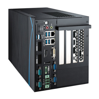
Page 58: Front Panel I/O Functions
COM 2 The item circled red is a hardware reset switch. Use this switch to reset the system without powering off the RCX-1000. Press and hold the reset switch for a few seconds, then reset will be enabled. ©Vecow RCX-1000 User Manual... - Page 59 S3, S5 Suspend to RAM, System off with standby power To power on RCX-1000, press the power button which will light the blue LED. To power off RCX-1000, you can either command shutdown by OS operation or simply press the power button. If system error appears, press and hold the power button for four seconds to shut down the machine directly.
- Page 60 The VGA output mode supports up to 1920x1200 resolution. If use VGA function will need a DVII to VGA module connecting to DVI-I device. Right is the DVII to VGA module picture ©Vecow RCX-1000 User Manual GETTING TO KNOW YOUR RCX-1000...
- Page 61 There are 6 USB 3.1 connections available supporting up to 10GB per second data rate in the front side of RCX-1000 series. It also compliant with the requirements of Super Speed (SS), high speed (HS), full speed (FS) and low speed (LS).
- Page 62 COM 1 COM 2 There are two 8-pin RJ-45 jacks supporting 10/100/1000 Mbps Ethernet ® connections on the front side of RCX-1000. LAN 1 is powered by Intel I219LM ® Ethernet engine, and LAN 2 is powered by Intel I210 Ethernet engine. When LAN 1 works in normal status, iAMT 11.0 function is enabled.
- Page 63 To utilize the audio function on the Windows platform, you need to install ® corresponding drivers for both Intel C246 chipset and Realtek ALC892 codec. Please refer to chapter four for more details on driver installation. ©Vecow RCX-1000 User Manual GETTING TO KNOW YOUR RCX-1000...
- Page 64 COM 1 COM 2 2.2.10 Front-access SSD/HDD Tray There are four front-access 2.5" SSD/HDD trays on the front side of RCX-1000. Press the trigger to open the SSD/HDD tray which has up to 8TB available. 2.2.11 Power Terminal Block COM 3...
- Page 65 • 3-KVRMS Isolation for 1 minute per UL 1577 • CSA Component Acceptance Notice 5A, IEC 60950-1 and IEC 61010-1 End Equipment Standards PIN 1 ~ 8 PIN 11 ~ 18 • GB4943.1-2011 CQC Certified ©Vecow RCX-1000 User Manual GETTING TO KNOW YOUR RCX-1000...
- Page 66 OUTPUT 8 SIO_GPO0 OUTPUT 9 SIO_GPO1 OUTPUT 10 SIO_GPO2 OUTPUT 11 SIO_GPO3 OUTPUT 12 SIO_GPO4 OUTPUT 13 SIO_GPO5 OUTPUT 14 SIO_GPO6 OUTPUT 15 SIO_GPO7 GND_ISO_DIO2 External 6-40VDC (NPN) External 6-48VDC (PNP) ©Vecow RCX-1000 User Manual GETTING TO KNOW YOUR RCX-1000...
- Page 67 DO Signal circuit in SINK mode (NPN) Source (PNP) DIO_VDC (20) LOAD 7.2K ISOLATION 6-40V (11) (300mA) 1.5K GNDI GNDO GNDO (10.19) Internal Circuit External Device GNDO DO Signal circuit in source mode (PNp) ©Vecow RCX-1000 User Manual GETTING TO KNOW YOUR RCX-1000...
- Page 68 (5-wire) (9-wire) (3-wire) TXD- TXD- DATA- TXD+ TXD+ DATA+ RXD+ RXD+ ----------- RXD- RXD- ----------- 1, 2 3, 4 ----------- RTS- ----------- ----------- RTS+ ----------- ----------- CTS+ ----------- ----------- CTS- ----------- ©Vecow RCX-1000 User Manual GETTING TO KNOW YOUR RCX-1000...
-
Page 69: Main Board Expansion Connectors
2.3 Main Board Expansion Connectors 2.3.1 Front View of RCX-1000 Main Board With Connector Location SODIMM 2 SODIMM 1 CN10 JCOM2 SATA4 SATA3 JCOM1 SODIMM 4 SODIMM 3 JBAT1 SATA1 SATA2 JUSB1 JDEBUG1 BIOS HDD_PWR1 HDD_PWR2 SYS_FAN2 SYS_FAN1 Super I/O... - Page 70 2.3.2 Rear View of RCX-1000 Main Board With Connector Location CN17 ©Vecow RCX-1000 User Manual GETTING TO KNOW YOUR RCX-1000...
- Page 71 Fan PWM 2.3.4 JBAT1 : Battery The RCX-1000's real-time clock is powered by a lithium battery. It is equipped with Panasonic BR2032 190mAh lithium battery. It is recommended that you do not replace the lithium battery on your own. If the battery needs to be changed, please contact the Vecow RMA service team.
- Page 72 +V3.3S +V3.3S Reserved +V3.3S +V3.3A PLTRST_PCIE# WAKE# Reserved CLKOUT_100M_X4_P0 CLKOUT_100M_X4_N0 PCIE_TXP21 PCIE_TXN21 PCIE_RXP21 PCIE_RXN21 Reserved Reserved PCIE_TXP22 PCIE_TXN22 PCIE_RXP22 PCIE_RXN22 PCIE_TXP23 PCIE_TXN23 PCIE_RXP23 PCIE_RXN23 PCIE_TXP24 PCIE_TXN24 PCIE_RXP24 PCIE_RXN24 CLKOUT_100M_X4_P1 CLKOUT_100M_X4_N1 Reserved ©Vecow RCX-1000 User Manual GETTING TO KNOW YOUR RCX-1000...
- Page 73 Pin No. Definition Pin No. Definition Reserved +V12S +V12S +V12S +V12S +V12S CLKOUT_100M_X16_P2 SM_SLOT_CLK CLKOUT_100M_X16_N2 SM_SLOT_DAT USB_P8_DP USB_P8_DN +V3.3S +V3.3S +V3.3S +V3.3A PLTRST_PCIE# WAKE# Reserved CLKOUT_100M_X16_P0 CLKOUT_100M_X16_N0 PEG_TXP_0 PEG_TXN_0 PEG_RXP_0 PEG_RXN_0 Reserved ©Vecow RCX-1000 User Manual GETTING TO KNOW YOUR RCX-1000...
- Page 74 PEG_TXN_2 PEG_RXP_2 PEG_RXN_2 PEG_TXP_3 PEG_TXN_3 PEG_RXP_3 PEG_RXN_3 PCIE_RXP7 PCIE_RXN7 CLKOUT_100M_X16_P1 CLKOUT_100M_X16_N1 PEG_TXP_4 PEG_TXN_4 PEG_RXP_4 PEG_RXN_4 PEG_TXP_5 PEG_TXN_5 PEG_RXP_5 PEG_RXN_5 PEG_TXP_6 PEG_TXN_6 PEG_RXP_6 PEG_RXN_6 PEG_TXP_7 PEG_TXN_7 PEG_RXP_7 PEG_RXN_7 Reserved Reserved PEG_TXP_8 PEG_TXN_8 ©Vecow RCX-1000 User Manual GETTING TO KNOW YOUR RCX-1000...
- Page 75 PEG_RXN_8 PEG_TXP_9 PEG_TXN_9 PEG_RXP_9 PEG_RXN_9 PEG_TXP_10 PEG_TXN_10 PEG_RXP_10 PEG_RXN_10 PEG_TXP_11 PEG_TXN_11 PEG_RXP_11 PEG_RXN_11 PEG_TXP_12 PEG_TXN_12 PEG_RXP_12 PEG_RXN_12 PEG_TXP_13 PEG_TXN_13 PEG_RXP_13 PEG_RXN_13 PEG_TXP_14 PEG_TXN_14 PEG_RXP_14 PEG_RXN_14 PEG_TXP_15 PEG_TXN_15 PEG_RXP_15 PEG_RXN_15 PCIE_TXP7 PCIE_TXN7 ©Vecow RCX-1000 User Manual GETTING TO KNOW YOUR RCX-1000...
- Page 76 1000. It supports higher storage capacity with less cabling effort and smaller required space. The pin assignments of SATA1, SATA2, SATA3, and SATA4 are listed in the following table : Pin No. Definition Pin No. Definition ©Vecow RCX-1000 User Manual GETTING TO KNOW YOUR RCX-1000...
- Page 77 HDD_PWR1 HDD_PWR2 The RCX-1000 is also equipped with two SATA power connectors. It supports 5V (Up to 3A) and 12V (Up to 3A) currents to the hard drive or SSD. The pin assignments of HDD_PWR1 and HDD_PWR2 are listed in the following table : Pin No.
- Page 78 2.3.11 JUSB1 : Internal Dual Port USB 2.0 JUSB1 The RCX-1000 main board provides up to two expansion USB ports using plug-and-play for Dongle Key or LCD touch panel. The USB interface supports 480Mbps transfer rate which complies with high speed USB specification Rev.
- Page 79 0. The pin assignments of MPCIE1, MPCIE2 are listed in the following table : Pin No. Definition Pin No. Definition Reserved +3.3Vaux Reserved Reserved +1.5V Reserved Reserved Status Reserved ©Vecow RCX-1000 User Manual GETTING TO KNOW YOUR RCX-1000...
- Page 80 Reserved +3.3Vaux USB_D+ USB_D- PETp0 PETn0 SMB_DATA SMB_CLK +1.5V PERp0 PERn0 +3.3Vaux PERST# Reserved reserved Reserved Mechanical Key Reserved REFCLK+ Reserved REFCLK- Reserved Reserved CLKREQ# Reserved Reserved 1.5V Reserved WAKE# 3.3Vaux ©Vecow RCX-1000 User Manual GETTING TO KNOW YOUR RCX-1000...
- Page 81 COM 1 COM 2 RCX-1000-12 only 12V DC power input, CN6 support 12V output. RCX-1000 24V to 36V DC power input, CN6 support 12V output. The pin assignments of CN6 are listed in the following table : Pin No. Definition Pin No.
- Page 82 The pin assignments of J2 are listed in the following table : Group Pin No. Definition HDD_LED_P HDD LED HDD_LED_N FP_RST_BTN_N RESET BUTTON Ground PWR_LED_P POWER LED PWR_LED_N FP_PWR_BTN_IN POWER BUTTON Ground 2.3.15 SODIMM1, SODIMM2, SODIMM3, SODIMM4 SODIMM2 SODIMM1 SODIMM4 SODIMM3 ©Vecow RCX-1000 User Manual GETTING TO KNOW YOUR RCX-1000...
- Page 83 SODIMM_2 SODIMM_2 SODIMM_4 SODIMM_2 SODIMM_1 SODIMM_2 SODIMM_1 SODIMM_4 SODIMM_4 SODIMM_3 SODIMM Quantity Location SODIMM_2 SODIMM_2, SODIMM_4 SODIMM_2, SODIMM_4, SODIMM_1 SODIMM_2, SODIMM_4, SODIMM_1, SODIMM_3 ©Vecow RCX-1000 User Manual GETTING TO KNOW YOUR RCX-1000...
- Page 84 RESERVED/PETp1 ALERT# (O)(0/3.3V) 12C_CLK (I)(0/3.3V) RESERVED/PERn1 12C_DATA (I/O)(0/3.3V) RESERVED/PERp1 PEWAKE0# (I/O) (0/3.3V) PERST0# (I)(0/3.3V) CLKREQ0# (I/O) (0/3.3V) REFCLKn0 REFCLKp0 PETn0 PETp0 PERn0 PERp0 Module Key Module Key Module Key Module Key ©Vecow RCX-1000 User Manual GETTING TO KNOW YOUR RCX-1000...
- Page 85 PCIe or SATA, or Solid State Storage Devices (SSD). Module card types include 2242, 2260, 2280 Pin Out : Pin No. Definition Pin No. Definition 3.3V 3.3V 3.3V SCUSCLK (3.2KHz)(O) PEDET (NC-PCIe/GND- (0/3.3V) SATA) Connector Key ©Vecow RCX-1000 User Manual GETTING TO KNOW YOUR RCX-1000...
- Page 86 PERST# (I/O)(O)(0/3.3V) or N/C PETp0/SATA-A+ PETn0/SATA-A- PERp0/SATA-B- PERp0/SATA-B+ DEVSLP (O) PETp1 PETn1 PERp1 PERn1 PETp2 PETn2 3.3V PERp2 3.3V PERn2 3.3V 3.3V PETp3 DAS/DDS# (I/O)/LED1# (I) PETn3 (0/3.3V) PERp3 3.3V PERn3 3.3V ©Vecow RCX-1000 User Manual GETTING TO KNOW YOUR RCX-1000...
- Page 87 UIM_VPP_2 SIO_GPI80 DIO2_GPI0 SIO_GPI81 DIO2_GPI1 SIO_GPI82 DIO2_GPI2 SIO_GPI83 DIO2_GPI3 SIO_GPI84 DIO2_GPI4 SIO_GPI85 DIO2_GPI5 SIO_GPI86 DIO2_GPI6 SIO_GPI87 DIO2_GPI7 SIO_GPO70 DIO2_GPO0 SIO_GPO71 DIO2_GPO1 SIO_GPO72 DIO2_GPO2 SIO_GPO73 DIO2_GPO3 SIO_GPO74 DIO2_GPO4 SIO_GPO75 DIO2_GPO5 SIO_GPO76 DIO2_GPO6 ©Vecow RCX-1000 User Manual GETTING TO KNOW YOUR RCX-1000...
- Page 88 UART4_MODE0 UART3_MODE1 UART4_MODE1 UART3_MODE2 UART4_MODE2 SP338E_TERM_COM3 SP338E_TERM_COM4 +V3.3S +V3.3S +V3.3S +V3.3S SIO_GP60 SIO_GP47 SIO_GP61 SIO_GP62 USB3_PCH_RXN1 USB3_PCH_RXN2 USB3_PCH_RXP1 USB3_PCH_RXP2 USB3_PCH_TXN1 USB3_PCH_TXN2 USB3_PCH_TXP1 USB3_PCH_TXP2 USB_P1_DP USB_P2_DP USB_P1_DN USB_P2_DN +V5A +V5A +V5A +V5A ©Vecow RCX-1000 User Manual GETTING TO KNOW YOUR RCX-1000...
-
Page 89: Main Board Jumper Settings
You may configure your card to match the needs of your application by DIP switch. As below show the deep switch on and off. 1 : OFF 1 : ON 1 : ON 2 : OFF 2 : OFF 2 : ON ©Vecow RCX-1000 User Manual GETTING TO KNOW YOUR RCX-1000... - Page 90 2.4.3 JP1 : CPU PCIe x 16 (CN9) Configuration JCFG1 CPU PCIe x 16 (CN9) configuration table as follows : PCIe Configuration Header 1 x8, 2 x4 (3-5) (4-6) 2 x 8 (3-5) (2-4) 1 x16 (1-3) (2-4) ©Vecow RCX-1000 User Manual GETTING TO KNOW YOUR RCX-1000...
- Page 91 2.4.5 JUSB_PWR1 Pin Header : USB Wake Up JUSB_PWR1 Pin No. Definition (1-2) USB 3.0 and USB 2.0 Wake Up Enable (Default) (2-3) USB 3.0 and USB 2.0 Wake Up Disable ©Vecow RCX-1000 User Manual GETTING TO KNOW YOUR RCX-1000...
- Page 92 2.4.6 FAN2 Header FAN2 Pin No. Definition (1-2) SYS_FAN2 : PCH PWM Control (Default) (2-3) SYS_FAN2 : Full Speed ©Vecow RCX-1000 User Manual GETTING TO KNOW YOUR RCX-1000...
-
Page 93: Ignition Control
2.5 Ignition Control 2.5.1 SW1 : Ignition Control The RCX-1000 series provide ignition power control feature for in-vehicle applications. The built-in MCU monitors the ignition signal and turns on/off the system according to pre-defined on/off delay period. ©Vecow RCX-1000 User Manual... - Page 94 2.5.2 Adjust Ignition Control Modes The RCX-1000 series provide sixteen modes of different power on/off delay periods adjustable via rotary switch. The default rotary switch is set to 0 in ATX/ AT power mode. The modes are listed in the following table :...
- Page 95 Note : 1. DC power source and IGN share the same ground. 2. RCX-1000 supports 6V to 36V wide range DC power input in ATX/AT mode. In Ignition mode, the input voltage is fixed to 12V/24V for car battery scenario.
-
Page 96: Chapter 3 System Setup
SYSTEM SETUP 3.1 How to open your RCX-1000 3.1.1 RCX-1400FR/1400F Remove F-Head 6#-32 screws (circled in red) on the top cover. (12 places) 3.1.2 RCX-1400R/1400 Remove F-Head 6#-32 screws (circled in red) on the top cover. (9 places) ©Vecow RCX-1000 User Manual... -
Page 97: Installing Cpu
3.1.3 RCX-1200 3.2 Installing CPU Step 1 Remove PH M3x6L screws (10 places) ©Vecow RCX-1000 User Manual SYSTEM SETUP... -
Page 98: Installing Ddr4 So-Dimm Modules
3.3 Installing DDR4 SO-DIMM Modules Step 1 Install DDR4 RAM module Step 2 Make sure the RAM module into SO-DIMM slot. is locked by the memory slots (red). ©Vecow RCX-1000 User Manual SYSTEM SETUP... -
Page 99: Installing Mini Pcie Card
Step 1 Install Mini PCIe card into Step 2 Fasten one M2.5 screws. the Mini PCIe slot. 3.5 Installing M.2 (Key E/Key M) Step 1 Install M.2 card into the Mini PCIe slot. Step 2 Fasten one M3 screws. ©Vecow RCX-1000 User Manual SYSTEM SETUP... -
Page 100: Installing Antenna Cable
3.6 Installing Antenna Cable Step 1 Remove one rubber cork from the rear panel (pick the location you want). RCX-1400FR/1400F/1400R/1400 RCX-1200 ©Vecow RCX-1000 User Manual SYSTEM SETUP... -
Page 101: Installing Sim Card
Step 3 Fasten washer 1, washer 2, and on Antenna cable connector 3.7 Installing Sim Card Step 1 Remove SIM cover Step 2 Install SIM card in the (Remove 6#-32 x 5L screws). marked yellow area. ©Vecow RCX-1000 User Manual SYSTEM SETUP... -
Page 102: Installing Pci/Pcie Card
RCX-1400 series : supports the maximum length 230 mm (without card bracket) of PCI/PCIe expansion card. RCX-1200 series : supports the maximum length 220 mm (without card bracket) of PCI/PCIe expansion card. Step 1 Remove M3x5L screws and PCI bracket. ©Vecow RCX-1000 User Manual SYSTEM SETUP... - Page 103 Step 2 Install the PCI/PCIe Card and lock it in place. Step 3 Fasten one M3x5L screws. Notice : For RCX-1400FR/1400F/1400R/1400 Series, please press the clip before removing the card. unlock ©Vecow RCX-1000 User Manual SYSTEM SETUP...
-
Page 104: Installing Ssd/Hhd
3.9.1 External SSD/HDD for RCX-1400FR/1400R Series Step 1 Open SSD/HDD Door Step 2 Insert 2.5" SSD/HDD into the tray. Step 3 Push back and close the Step 4 Lock the SSD/HDD tray SSD/HDD tray. with the key. unlock lock ©Vecow RCX-1000 User Manual SYSTEM SETUP... - Page 105 3.9.2 Internal SSD/HDD for RCX-1400F/1400 Step 1 Remove 6#-32 x 5L screws. Step 2 Open the HDD door and Insert 2.5" SSD/HDD into the tray. Step 3 Fasten four F Head M3x4L screws (1 set). ©Vecow RCX-1000 User Manual SYSTEM SETUP...
- Page 106 3.9.3 Internal SSD/HDD for RCX-1200 Step 1 Open bottom case Step 2 Remove two 6#-32 x 5L screws and two M3 x 4L screws. ©Vecow RCX-1000 User Manual SYSTEM SETUP...
- Page 107 Step 3 Remove HDD tray. Step 4 Remove cable (yellow mark) and screws (red mark). ©Vecow RCX-1000 User Manual SYSTEM SETUP...
-
Page 108: Mounting Your Rcx-1000
3.10 Mounting Your RCX-1000 Step 1 Install wall mount to RCX-1000 bottom. Step 2 Install four F head #6-32x6L screws. ©Vecow RCX-1000 User Manual SYSTEM SETUP... -
Page 109: Cleaning The Air Filter Of Rcx-1400Fr/1400F
3.11 Cleaning the Air filter of RCX-1400FR/1400F Step 1 Remove two F-Head 6#-32 screws (circled in red) on the top cover. Step 2 Take out the removable filter. (Cleaning the filter by toothbrush is recommended.) ©Vecow RCX-1000 User Manual SYSTEM SETUP... -
Page 110: Installing The Hold Down Bar For Rcx-1400F/1400 Series
Step 2 Adjust the plate left or right to fix the card and then fasten two screws on the marked yellow area. Step 3 Turn the screw (circle in red) left or right with Phillips screwdriver to adjust the pad up and down. down ©Vecow RCX-1000 User Manual SYSTEM SETUP... -
Page 111: Chapter 4 Bios Setup
Figure 4-1 : Entering Setup Screen BIOS provides an interface for users to check and change system configuration. The BIOS setup program is accessed by pressing the <Del> key when POST display output is shown. ©Vecow RCX-1000 User Manual BIOS SETUP... -
Page 112: Main
Set the time. Use <Tab> to switch between time elements. 4.3 Advanced Figure 4-3 : BIOS Advanced Menu Select advanced tab to enter advanced BIOS setup options, such as CPU configuration, SATA configuration, and USB configuration. ©Vecow RCX-1000 User Manual BIOS SETUP... - Page 113 Technology). When disabled only one thread per core is enabled. Enable/disable CPU Advanced Encryption Standard instructions. Intel Trusted Execution Technology ® Enables utilization of additional hardware capabilities provided by Intel Trusted Execution Technology. Changes require a full power cycle to take effect. ©Vecow RCX-1000 User Manual BIOS SETUP...
- Page 114 CPPCv2 interface to allow for hardware controlled P-states. Turbo Mode Turbo Mode. C states Enable or disable CPU C states. Enhanced C-states Enable/disable C1E. When enabled, CPU will switch to minimum speed when all cores enter C-State. ©Vecow RCX-1000 User Manual BIOS SETUP...
- Page 115 When disabled AMT BIOS Features are no longer supported and user is no longer able to access MEBx Setup. AMT Configuration ® Configure Intel Active Management Technology Parameters. ME Unconfig on RTC Clear State Disabling this option will cause ME not to unconfigure on RTC clear. ©Vecow RCX-1000 User Manual BIOS SETUP...
- Page 116 Enables or disables S3 video repost. 4.3.6 SMART Settings Figure 4-3-6 : SMART Settings SMART Self Test Run SMART self test on all HDDs during POST. 4.3.7 IT8786 Super IO Configuration Figure 4-3-7 : IT8786 Super IO Settings ©Vecow RCX-1000 User Manual BIOS SETUP...
- Page 117 Temperature Limit value of Fan Start (Degree C). (Range : 10~80) PWM Start Value (%) Default PWM Value of Fan. (Range : 15%~100%) Full Speed Temperature Temperature Limit value of Fan Full Speed (Degree C). (Range : 50~90) ©Vecow RCX-1000 User Manual BIOS SETUP...
- Page 118 Legacy Console Redirection Legacy Console Redirection Settings. Serial Port for Out-of-Band Management/Windows Emer ency Management Services (EMS) Console redirection enable or disable. 4.3.10 Intel TXT Information Figure 4-3-10 : Intel TXT Information Display Intel TXT information. ©Vecow RCX-1000 User Manual BIOS SETUP...
- Page 119 Globally Enables or Disables Hot-Plug support for the entire System. If system has Hot-Plug Capable Slots and this option set to Enabled, it provides a Setup screen for selecting PCI resource padding for Hot-Plug. ©Vecow RCX-1000 User Manual BIOS SETUP...
- Page 120 IP6 Configuration Policy Set IP6 Configuration Policy. PXE boot wait time Wait time to press ESC key to abort the PXE boot. Media detect count Number of times presence of media will be checked. ©Vecow RCX-1000 User Manual BIOS SETUP...
- Page 121 Controls the execution of UEFI and Legacy Storage OpROM. Video Allows more than two frequency ranges to be supported. Other PCI devices Determines OpROM execution policy for devices other than network, storage, or video. ©Vecow RCX-1000 User Manual BIOS SETUP...
- Page 122 Maximum time the device will take before it properly reports itself to the Host Controller. 'Auto' uses default value, for a root port it is 100 ms, for a hub port the delay is taken from the hub descriptor. ©Vecow RCX-1000 User Manual BIOS SETUP...
-
Page 123: Chipset
VT-d capability. Above 4GB MMIO BIOS assignment Enable/disable above 4GB MemoryMappedIO BIOS assignment. This is disabled automatically when aperture size is set to 2048MB. 4.4.1.1 Memory Configuration Figure 4-4-1-1 : Memory Information Displays memory information. ©Vecow RCX-1000 User Manual BIOS SETUP... - Page 124 2048MB aperture. To use this feature, please disable CSM Support. DVMT Pre-Allocated Select DVMT 5.0 Pre-Allocated (Fixed) Graphics Memory size used by the Internal Graphics Device. DVMT Total Gfx Mem Select DVMT5.0 Total Graphic Memory size used by the Internal Graphics Device. ©Vecow RCX-1000 User Manual BIOS SETUP...
- Page 125 Specify what state to go to when power is re-applied after a power failure (G3 state). S0 State : Always turn-on the system when power source plugged-in. S5 State : Always turn-off the system when power source plugged-in. ©Vecow RCX-1000 User Manual BIOS SETUP...
- Page 126 Enable/Disable the control of Active State Power Management on SA side of the DMI Link. Native PCIE Enable PCIE Express Native Support Enable/Disable. PCI Express device settings Bios options for PCI Express device setting. ©Vecow RCX-1000 User Manual BIOS SETUP...
- Page 127 On an edge detect from 0 to 1, the PCH starts a COMRESET initialization sequence to the device. SATA Device Type Identifies that the SATA port is connected to solid state drive or hard disk drive. ©Vecow RCX-1000 User Manual BIOS SETUP...
- Page 128 System Fan 2 speed control (High/Mid/Low). HDMI 4K Support (Digital Display Port) Enable HDMI 4K support for Digital Display Port only [Disable] : DP support 2160P HDMI support 1080P [Enable] : DP not support HDMI support 2160P ©Vecow RCX-1000 User Manual BIOS SETUP...
-
Page 129: Security
4.5 Security Figure 4-5 : BIOS Security Menu Administrator Password Set administrator password. User Password Set user password. Secure Boot Customizable Secure Boot Settings. ©Vecow RCX-1000 User Manual BIOS SETUP... - Page 130 User/Deployed, and CSM function is disabled. Secure Boot Mode Secure Boot mode selector Standard/Custom. In custom mode Secure Boot Variables can be configured without authentication. Key Management Enables expert users to modify Secure boot policy variables without full authentication. ©Vecow RCX-1000 User Manual BIOS SETUP...
-
Page 131: Boot
Boot Option Sets the system boot order. New Boot Option Policy Controls the placement of newly detected UEFI boot options. Hard Drive BBS Priorities Set the order of the Legacy devices in this group. ©Vecow RCX-1000 User Manual BIOS SETUP... -
Page 132: Save & Exit
Restore Defaults Restore/Load Default values for all the setup options. Save as User Defaults Save the changes done so far as User Defaults. Restore User Defaults Restore the User Defaults to all the setup options. ©Vecow RCX-1000 User Manual BIOS SETUP... -
Page 133: Appendix A : Isolated Dio Guide
APPENDIX A : Isolated DIO Guide A.1 Function Description The RCX-1000 offers two 16-bit Isolated DIO 20-pin terminal block connector, a watchdog timer. Isolated DIO pins are fix by Hardware design that cannot change in/out direction in runtime process. DIO definition is shown below :... - Page 134 DIO Connector (NPN, Default) 6-48V DC DIO_VDC (Pin 20) DO (Pin 11-18) DIO_GND (Pin 10, 19) Source Mode Device DIO Connector (PNP) 6-48V DC DIO_VDC (Pin 20) DO (Pin 11-18) DIO_GND (Pin 10, 19) ©Vecow RCX-1000 User Manual Appendix A...
- Page 135 Sample folder include sample program, driver library, and API library. Source folder include sample program source code that compile on Visual Studio 2008. A.4 Sample Sample folder include x32 and x64 versions, as shown right : Sample RCX1K.exe, as shown below : ©Vecow RCX-1000 User Manual Appendix A...
- Page 136 DO/DIO pin writable check button (pin 18 ~ pin 11/pin 18 ~ pin 11, pin 8 ~ pin 1) : User setting, DO/DIO pin writable of DIO configuration. Use for Read (DIO)/Write button activate. ©Vecow RCX-1000 User Manual Appendix A...
- Page 137 WDT counting by program timer after set WDT. Shown after Write button action. WDT setup day format texts (user setting) : User setting, WDT value, format : day'hour'minute'second. WDT counting day format text (read only) : WDT counting, format : day'hour'minute'second. ©Vecow RCX-1000 User Manual Appendix A...
-
Page 138: Appendix B : Software Functions
Mask ([15:0]) : In/Out, pin setting by hexadecimal bitmask 1 : Output; 0 : Input Return : TRUE (1) : Success; FALSE (0) : Fail (Initial error, or call by pointer error, or hardware problem) ©Vecow RCX-1000 User Manual Appendix B... - Page 139 Set isolated DIO output (DO) DO ([7:0]) : Output state, pin setting by hexadecimal bitmask 1 : High; 0 : Low Return : TRUE (1) : Success; FALSE (0) : Fail (Initial error, or hardware problem) ©Vecow RCX-1000 User Manual Appendix B...
- Page 140 FALSE (0) : Fail (Initial error, or setup 0 error, or hardware problem) BOOL CancelWDT () Cancel watchdog timer Return : TRUE (1) : Success; FALSE (0) : Fail (Initial error, or hardware problem) ©Vecow RCX-1000 User Manual Appendix B...
-
Page 141: Appendix C : Raid Functions
1. Please select SATA device to RAID mode on BIOS menu. Advanced → SATA Configuration → SATA Mode Selection → RAID (Skylake platform)/Intel RST Premium (Kaby Lake/Coffee Lake platform) 2. Please select Software Feature Mask Configuration on BIOS menu. ©Vecow RCX-1000 User Manual Appendix C... - Page 142 3. Use RST Legacy OROM → Disabled → Save Changes and Reset. 4. Into BIOS menu again, select Intel(R) Rapid Storage Technology on BIOS menu. 5. Select Create RAID Volume on BIOS menu. ©Vecow RCX-1000 User Manual Appendix C...
- Page 143 You can get the software from driver CD. Also, you can find the latest information and software directly from Intel's website. http://www.intel.com/p/en_US/support/highlights/chpsts/imsm The RAID environment has been done if you completed the steps above. ©Vecow RCX-1000 User Manual Appendix C...
- Page 144 "RAID 1". C.7 Disk Management : Partition the Disk After RAID 1 volume is created, you can see the figure of SATA device allocation. You will find "Volume_0000" in SATA device at BIOS menu. ©Vecow RCX-1000 User Manual Appendix C...
- Page 145 Then add "Logical Device" for Windows access. C.8 If One SATA HDD on RAID Volume is Out-of-use After RAID 1 volume is created, you can see the figure of SATA device allocation. HDD CAUTION Sign ©Vecow RCX-1000 User Manual Appendix C...
- Page 146 A warning will pop-up to ask you if the disk is not a member of the original RAID volume. If you press "Rebuild", it will replace the broken SATA HDD to the last SATA HDD of RAID volume. ©Vecow RCX-1000 User Manual Appendix C...
-
Page 147: Appendix D : Power Consumption
Transcend SATA SSD420 128GB SATA 1 Seagate HDD 500GB LAN1 (i219) 1.0 Gbps LAN2 (i210) 1.0 Gbps Graphics output Power plan Balance(Windows10 Power plan) Power Source Chroma 62006P-100-25 Test Program-1 BurnInTest Test Program-2 FurMark ©Vecow RCX-1000 User Manual Appendix D... - Page 148 Power without 2D without 3D Input Current Consumption Current Consumption Core™ i7-8700T 4.720A 42.48W 5.880A 52.92W Core™ i7-8700T 3.394A 40.73W 3.949A 47.39W Core™ i7-8700T 1.898A 45.54W 2.282A 54.76W Core™ i7-8700T 1.251A 45.03W 1.898A 68.32W ©Vecow RCX-1000 User Manual Appendix D...
- Page 149 Power without 2D without 3D Input Current Consumption Current Consumption Core™ i7-8700 6.453A 58.08W 8.803A 79.23W Core™ i7-8700 4.686A 56.23W 5.904A 70.85W Core™ i7-8700 2.587A 62.08W 3.092A 74.20W Core™ i7-8700 1.764A 63.51W 2.055A 73.98W ©Vecow RCX-1000 User Manual Appendix D...
- Page 150 3D Input Current Consumption Current Consumption ® Xeon E-2176G 8.490A 76.41W 10.409A 93.68W ® Xeon E-2176G 6.471A 77.65W 7.392A 88.71W ® Xeon E-2176G 3.344A 80.25W 4.209A 101.03W ® Xeon E-2176G 2.358A 84.88W 3.043A 109.56W ©Vecow RCX-1000 User Manual Appendix D...
- Page 151 Power on and boot to Win10 64-bit Run 100% CPU usage Run 100% CPU usage Power without 2D without 3D Input Current Consumption Current Consumption Core™ i7-8700 3.559A 85.40W 13.219A 317.26W Core™ i7-8700 2.452A 88.27W 9.033A 325.19W ©Vecow RCX-1000 User Manual Appendix D...
-
Page 152: Appendix E : Supported Memory & Storage List
*2 (Socket 1; Socket 2) PASS PASS PASS PASS *2 (Socket 3; Socket 4) PASS PASS PASS PASS *1 (Socket 1) *1 (Socket 2) PASS PASS PASS *1 (Socket 3) *1 (Socket 4) PASS PASS PASS ©Vecow RCX-1000 User Manual Appendix E... - Page 153 Kingston 4GB DDR4-2666 SO-DIMM KVR26S19S6/4 25ºC 25ºC Kingston 8GB DDR4-2666 SO-DIMM KVR26S19S8/8 25ºC 25ºC Kingston 16GB DDR4-2666 SO-DIMM KVR26S19D8/16 25ºC 25ºC ADATA 8GB DDR4-2666 SO-DIMM AD4S266638G19-BSSC 25ºC 25ºC ADATA 16GB DDR4-2666 SO-DIMM AD4S2666316G19-BSSC 25ºC ©Vecow RCX-1000 User Manual Appendix E...
- Page 154 M4D0-AGS1QCIK-H03 25ºC 25ºC SLINK 32G DDR4 2666 SO-DIMM J4BGDS2G8QHKC 25ºC 25ºC SLINK 32G DDR4 2666 SO-DIMM J4BGDS2G8QHKI 25ºC 25ºC SLINK 16G DDR4 2666 SO-DIMM J4AGDH1G8QHKC 25ºC 25ºC SLINK 8G DDR4 2666 SO-DIMM J48GDH1G8QHJC 25ºC ©Vecow RCX-1000 User Manual Appendix E...
- Page 155 256GB ISSS332-128GM 128GB ADATA ISSS332-256GM 256GB IM2P33F8-128GD 128GB ADATA IM2P33F8-256GD 256GB M.2 SSD Toshiba KXG50ZNV512G 512GB (PCIe) Phison ESMP256GTB3C2-E12 256GB FORESEE FSGMMC-256G 256GB ** If more help is needed, please contact Vecow Technical Support. ©Vecow RCX-1000 User Manual Appendix E...
-
Page 156: Appendix F : How To Install Power Supply
APPENDIX F : How to Install Power Supply F.1.1 HEP-600-24 Adapter AC Cable HEP-600C-24 GREEN BLACK WHITE F.1.2 HEP-600-24 Adapter DC Cable HEP-600C-24 ©Vecow RCX-1000 User Manual Appendix F... - Page 157 Adapter (PWS-600W) Output F.3.1 PWS-480W Adapter AC Cable Adapter (PWS-480W-WT) Input AC Power Cord BROWN BLACK GREEN/YELLOW GREEN BLUE WHITE F.3.2 PWS-480W Adapter DC Cable 3 Pin Terminal Block Adapter (PWS-480W-WT) Output BROWNx2 BLUEx2 ©Vecow RCX-1000 User Manual Appendix F...
- Page 158 F.4.1 PWS-360W Adapter AC Cable PWS-360W Power Adapter ON/OFF Switch AC 110V AC 220V AC Power Cord F.4.2 PWS-360W Adapter AC Cable PWS-360W ©Vecow RCX-1000 User Manual Appendix F...
- Page 159 F.5.1 RSP-1500-12 Adapter AC Cable RSP-1500-12 GREEN BLACK AC/L WHITE AC/N F.5.2 RSP-1500-12 Adapter DC Cable RSP-1500-12 ** If more help is needed, please contact Vecow technical support. ©Vecow RCX-1000 User Manual Appendix F...
- Page 160 No part of this publication may be reproduced in any form or by any means, electric, photocopying, or recording, without prior authorization from the publisher. The rights of all the brand names, product names, and trademarks belong to their respective owners. © Vecow Co., Ltd. 2019. All rights reserved.
Need help?
Do you have a question about the RCX-1000 and is the answer not in the manual?
Questions and answers