
Related Manuals for Vecow SPC-6000


Summary of Contents for Vecow SPC-6000
- Page 1 USER USER SPC-6000 Manual Manual Intel Atom ® x6425RE (Elkhart Lake) Fanless Embedded System, Ultra-Compact, Rugged, -40°C to 70°C Operation 1.0.0 Edition 20210513...
- Page 2 Record of Revision Version Date Remark Page Description 1.00 2021/05/13 Official Release ©Vecow SPC-6000 User Manual...
- Page 3 This manual is released by Vecow Co., Ltd. for reference purpose only. All product offerings and specifications are subject to change without prior notice. It does not represent commitment of Vecow Co., Ltd. Vecow shall not be liable for direct, indirect, special, incidental, or consequential damages arising out of the use of the product or documentation or any infringements upon the rights of third parties, which may result from such use.
- Page 4 Order Information Model GigE LAN 2.5G LAN USB 3.1 USB 2.0 DC-in SPC-6000 1 (External) ©Vecow SPC-6000 User Manual...
- Page 5 100W, 12V, 85V AC to 264V AC Power Adapter with 3-pin Terminal PWA-100W-12V Block M.2 Storage M.2 Key M/Key B PCIe Storage Module Module 5G Module 5G Module with Antenna 4G Module 4G/GPS Module with Antenna WiFi & Bluetooth WiFi & Bluetooth Module with Antenna ©Vecow SPC-6000 User Manual...
-
Page 6: Table Of Contents
CHAPTER 1 GENERAL INTRODUCTION 1.1 Overview 1.2 Features 1.3 Specifications of SPC-6000 1.4 Mechanical Dimension CHAPTER 2 GETTING TO KNOW YOUR SPC-6000 2.1 Packing List 2.2 Front Panel I/O & Functions 2.3 Rear Panel I/O & Functions 2.4 Connector/Jumper Locations 2.5 Main Board Jumper Settings... - Page 7 4.6 Boot Functions 4.7 Save & Exit APPENDIX A : Power Consumption APPENDIX B : Supported Memory & Storage List ©Vecow SPC-6000 User Manual...
-
Page 8: Chapter 1 General Introduction
Graphics 32EU, this device delivers DVI-I and DisplayPort outputs, providing uncompromised visual performance in a compact form factor. Vecow SPC-6000 is ideal for modern AI inferencing and computer vision applications at the edge including Smart Retail, Factory Automation, Traffic Vision, Robotic Control, and any AIoT/Industry 4.0 applications. -
Page 9: Features
• External Nano SIM socket supports 5G/WiFi/4G/3G/LTE/GPRS/UMTS • 12V DC Power Input • Supports Software Ignition Power Control and TPM 2.0 • Optional VHub One-Stop AIoT Solution Service supports OpenVINO based AI accelerator and advanced Edge AI applications ©Vecow SPC-6000 User Manual GENERAL INTRODUCTION... -
Page 10: Specifications Of Spc-6000
1.3 Specifications of SPC-6000 System ® Processor Intel Atom x6425RE Processor (Elkhart Lake) BIOS IT8786E Memory 1 DDR4 3200MHz SO-DIMM, up to 32GB Windows 10, Linux Graphics ® ® Processor Intel UHD Graphics for 10th Gen Intel Processors Dual Display : Interface •... - Page 11 5% to 95% Humidity, non-condensing Relative Humidity 95% at 70°C • IEC 60068-2-27 Shock • SSD : 50G @wallmount, Half-sine, 11ms • IEC 60068-2-64 Vibration • SSD : 5Grms, 5Hz to 500Hz, 3 Axis CE, FCC, EN50155, EN50121-3-2 ©Vecow SPC-6000 User Manual GENERAL INTRODUCTION...
-
Page 12: Mechanical Dimension
1.4 Mechanical Dimension Unit : mm (inch) 136.2 (5.36) 121.2 (4.77) 106.2 (4.18) ©Vecow SPC-6000 User Manual GENERAL INTRODUCTION... -
Page 13: Chapter 2 Getting To Know Your Spc-6000
GETTING TO KNOW YOUR SPC-6000 2.1 Packing List Item Description SPC-6000 Embedded System Driver/User Manual DVD Item Description Outlook Usage PHILLPIS M4x16L with Mounting 53-24D6416-30B washer, Ni PHILLPIS 53-2426204-80B M3*4L Wall mount M3x4L 53-2466204-30B bracket Terminal block 3-pin (5.0mm) DC-IN... -
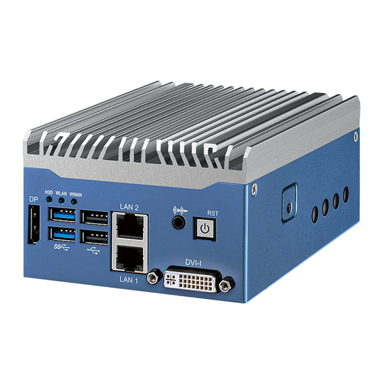
Page 14: Front Panel I/O & Functions
2.2 Front Panel I/O & Functions In Vecow's SPC-6000 series family, all I/O connectors are located on the front panel. Most of the general connections to the computer device, such as Display port, USB 3.2, USB 2.0, LAN Jack, Audio Jack and DVI-I, are placed on the front panel. - Page 15 There are 2 USB 3.2 Gen1 connections available supporting up to 5GB per second data rate in the front side of SPC-6000. It is also compliant with the requirements of Super Speed (SS), high speed (HS), full speed (FS) and low speed (LS).
- Page 16 2.2.5 USB 2.0 There are 2 USB 2.0 ports available supporting up to 480MB per second data rate in the front side of SPC-6000. They are also compliant with the requirements of high speed (HS), full speed (FS) and low speed (LS).
- Page 17 2.2.7 Audio Jack (Line-out only) There is a Line-out only connectors which in the front side of SPC-6000. Onboard Realtek ALC888S-VD audio codec supports 7.1 channel HD audio ® and fully complies with Intel High Definition Audio (Azalia) specifications. To utilize the audio function in Windows platform, you need to install corresponding drivers for Realtek ALC888S-VD codec.
-
Page 18: Rear Panel I/O & Functions
RS-422 or RS-485, you can find the settings in BIOS. BIOS Setting Function RS-232 COM 1 RS-422 (5-wire) COM 2 RS-422 (9-wire) COM 3 COM 4 RS-485 RS-485 w/z auto-flow control ©Vecow SPC-6000 User Manual GETTING TO KNOW YOUR SPC-6000... -
Page 19: Connector/Jumper Locations
2.4 Connector/Jumper Locations 2.4.1 SPC-6000 Main Board Top Side View JDIO2 JDIO1 JUSB1 M2E_CN1 DIMM1 LAN1 BAT1 DVI-I M2M_CN1 M2B_CN1 SATA1 HDD_PWR 2.4.2 SPC-6000 Main Board Bottom Side View M2B_SIM1 M2B_LED1 M2E_LED1 LED1 ©Vecow SPC-6000 User Manual GETTING TO KNOW YOUR SPC-6000... - Page 20 Pin No. Function +3V_BAT 2.4.4 CN9 : Audio Jack There is a audio line out connectors in the top side of SPC-6000. Onboard Realtek ALC888S-VD audio codec supports 7.1 channel HD audio and fully ® complies with Intel High Definition Audio (Azalia) specifications. To utilize the audio function in Windows platform, you need to install corresponding drivers ®...
- Page 21 2.4.6 JUSB1 : Internal USB 2.0 Connector JUSB1 The SPC-6000 series main board provides two expansion USB ports. The USB interface supports 480Mbps transfer rate which comply with high speed USB specification Rev. 2.0. The USB interface is accessed through one 10-pin JST 1.0mm connector.
- Page 22 M2E_CN1 are listed in the following table : Pin No. Signal Name Pin No. Signal Name 3.3V 3.3V ALERT# (O)(0/3.3V) 12C_CLK (I)(0/3.3V) 12C_DATA (I/O)(0/3.3V) PEWAKE0# (I/O)(0/3.3V) PERST0# (I)(0/3.3V) CLKREQ0# (I/O)(0/3.3V) REFCLKn0 ©Vecow SPC-6000 User Manual GETTING TO KNOW YOUR SPC-6000...
- Page 23 Signal Name REFCLKp0 PERn0 PERp0 PETn0 PETp0 Module Key Module Key Module Key Module Key Module Key Module Key Module Key Module Key LED2# (O)(od) LED1# (O)(od) 3.3V USB_D- 3.3V USB_D+ ©Vecow SPC-6000 User Manual GETTING TO KNOW YOUR SPC-6000...
- Page 24 2260/3042/3052. The pin assignments of M2B_CN1 are listed in the following table : Pin No. Signal Name Pin No. Signal Name 3.3V 3.3V 3.3V CONFIG_1 SIM DETECT PEWAKE# REFCLKp CLKREQ# REFCLKn PERST# ©Vecow SPC-6000 User Manual GETTING TO KNOW YOUR SPC-6000...
- Page 25 UIM-PWR PETp1/USB3.1-TX+ UIM-DATA PETp1/USB3.1-TX- UIM-CLK UIM-RESET PETp1/USB3.1-RX+ PETp1/USB3.1-RX- Module Key Module Key Module Key Module Key Module Key Module Key Module Key Module Key LED_1# W_DISABLE1 USB- FULL_CARD_PWR_OFF/ON USB+ 3.3V 3.3V ©Vecow SPC-6000 User Manual GETTING TO KNOW YOUR SPC-6000...
- Page 26 Pin No. Signal Name 3.3V 3.3V 3.3V PEDET (NC-PCIe/GND-SATA) Module Key Module Key Module Key Module Key Module Key Module Key Module Key Module Key Module Key PEWAKE# REFCLKp CLKREQ# REFCLKn PERST# ©Vecow SPC-6000 User Manual GETTING TO KNOW YOUR SPC-6000...
- Page 27 Pin No. Signal Name Pin No. Signal Name PETp0/SATA-A+ PETp0/SATA-A- PERp0/SATA-B- PERp0/SATA-B+ DEVSLP PETp1 PETn1 PERp1 PERn1 3.3V 3.3V 3.3V 3.3V LED1# (I)(0/3.3V) 3.3V 3.3V ©Vecow SPC-6000 User Manual GETTING TO KNOW YOUR SPC-6000...
- Page 28 Pin No. RS-232 Port (5-wire) (9-wire) (3-wire) TXD- TXD- DATA- TXD+ TXD+ DATA+ RXD+ RXD+ -------- RXD- RXD- -------- -------- RTS- -------- -------- RTS+ -------- -------- CTS+ -------- -------- CTS- -------- ©Vecow SPC-6000 User Manual GETTING TO KNOW YOUR SPC-6000...
- Page 29 2.4.12 CN7 : External USB 3.2 Gen1 Connector There are 2 USB 3.2 Gen1 connections available supporting up to 5GB per second data rate in the top side of SPC-6000 series. They are also compliant with the requirements of SuperSpeed (SS), high speed (HS), full speed (FS) and low speed (LS).
- Page 30 LED indicators to present Active/Link/Speed status of the connection. LED Location LED Color 10/100Mbps 1000Mbps 2500Mbps Green/ Solid Solid Left Yellow Green Yellow Twinkling Twinkling Twinkling Right Green Green Green Green ©Vecow SPC-6000 User Manual GETTING TO KNOW YOUR SPC-6000...
- Page 31 2.4.14 DP1 : Display port SPC-6000 support a Display Ports and up to 4096 x 2304 pixels resolution. 2.4.15 CN1 : DC Power Input SPC-6000 supports 12V DC power input by wire-to-board connector in the top side. Pin No. Definition Chassis-GND ©Vecow SPC-6000 User Manual...
- Page 32 2.4.16 SATA1 : SATA III Connector SATA1 There are two high performance Serial ATA III (SATA III) on the SPC-6000 series. They support higher storage capacity with less cabling effort and smaller required space. The pin assignments of SATA1 listed in the following table : Pin No.
- Page 33 SIO_GPO73 SIO_GPI84 SIO_GPO74 SIO_GPI85 SIO_GPO75 SIO_GPI86 SIO_GPO76 SIO_GPI87 SIO_GPO77 +3.3V +3.3V 2.4.19 SW2 : RESET Button Pin assignment as the following table : Pin No. Definition Pin No. Definition FP_RST_BTN_N FP_RST_BTN_N ©Vecow SPC-6000 User Manual GETTING TO KNOW YOUR SPC-6000...
- Page 34 2.4.20 M2B_SIM1 : Nano SIM Card Socket for M.2 key B Slot M2B_SIM1 The Nano SIM card socket is support Push-Push type. Please make sure to unplug the system power before inserting the Nano SIM card. ©Vecow SPC-6000 User Manual GETTING TO KNOW YOUR SPC-6000...
-
Page 35: Main Board Jumper Settings
2.5 Main Board Jumper Settings 2.5.1 Top View of SPC-6000 Main Board With Jumper Location The figure below is the top view of the SPC-6000 main board. It shows the location of the jumpers You may configure your card to match the needs of your application by setting jumpers. - Page 36 2.5.3 JP2 : Power Selection for EXT and INT USB 3.2 Gen1/USB 2.0 Ports Pin No. Definition +5V Standby Power (default) +5V System Power 2.5.4 JP3 : I225 SPI Flash Security Pin No. Definition enable (default) disable ©Vecow SPC-6000 User Manual GETTING TO KNOW YOUR SPC-6000...
-
Page 37: Chapter 3 System Setup
SYSTEM SETUP 3.1 How to Open Your SPC-6000 Step 1 Turn SPC-6000 bottom side up to remove two M3 screws. Step 2 Remove the bottom cover. ©Vecow SPC-6000 User Manual SYSTEM SETUP... -
Page 38: Installing Ddr4 So-Dimm Modules
3.2 Installing DDR4 SO-DIMM Modules Step 1 Find DDR4 SO-DIMM socket. Step 2 Install DDR4 RAM module into SO-DIMM socket. Step 3 Finished. ©Vecow SPC-6000 User Manual SYSTEM SETUP... -
Page 39: Installing M.2 (Keye, Keyb, Key M)
3.3 Installing M.2 (KeyE, KeyB, Key M) Step 1 Install M.2 into the M.2 slot. Step 2 Fasten a PHILLIPS M3 screw ©Vecow SPC-6000 User Manual SYSTEM SETUP... -
Page 40: Installing Sim Card
3.4 Installing SIM Card Step 1 Open the SIM card cover. Step 2 Install SIM card into to the SIM card slot and then close the SIM card cover. ©Vecow SPC-6000 User Manual SYSTEM SETUP... -
Page 41: Installing Antenna Cable
3.5 Installing Antenna Cable Step 1 Check antenna cable and washers. Step 2 Install antenna cable and then fasten washer and nut. ©Vecow SPC-6000 User Manual SYSTEM SETUP... -
Page 42: Mounting Your Spc-6000
3.6 Mounting Your SPC-6000 3.6.1 Wall mount 3.6.2 DIN-Rail ©Vecow SPC-6000 User Manual SYSTEM SETUP... -
Page 43: Chapter 4 Bios Setup
Figure 4-1 : Entering Setup Screen BIOS provides an interface for users to check and change system configuration. The BIOS setup program is accessed by pressing the <Del> key when POST display output is shown. ©Vecow SPC-6000 User Manual BIOS SETUP... -
Page 44: Main Manu
Set the time. Use <Tab> to switch between time elements. 4.3 Advanced Functions Figure 4-3 : BIOS Advanced Menu Select advanced tab to enter advanced BIOS setup options, such as CPU configuration, Network configuration, and USB configuration. ©Vecow SPC-6000 User Manual BIOS SETUP... - Page 45 Intel (VMX) Virtualization Technology When enabled, a VMM can utilize the additional hardware capabilities provided by Vanderpool Technology. Active Processor Cores Number of cores to enable in each processor package. Enable/disable AES (Advanced Encryption Standard). ©Vecow SPC-6000 User Manual BIOS SETUP...
- Page 46 C states Enable/Disable CPU Power Management. Allows CPU to go to C states when it's no 100% utilized. Enhanced C-states Enable/disable C1E. When enabled, CPU will switch to minimum speed when all cores enter C-State. ©Vecow SPC-6000 User Manual BIOS SETUP...
- Page 47 4.3.3 PCH-FW Configuration Figure 4-3-3 : PCH-FW Settings ME State When Disabled ME will be put into ME Temporarily Disabled Mode. ME Unconfig on RTC Clear When Disabled ME will not be unconfigured on RTC Clear. ©Vecow SPC-6000 User Manual BIOS SETUP...
- Page 48 Gfx LLC allocation to minimize impact of Gfx workload on LLC. 4.3.5 Trusted Computing Figure 4-3-5 : Trusted Computing Control the TPM device status and display related information if TPM chip is present. ©Vecow SPC-6000 User Manual BIOS SETUP...
- Page 49 Select the highest ACPI sleep state the system will enter when the SUSPEND button is pressed. 4.3.7 SMART Settings Figure 4-3-7 : SMART Settings SMART Self Test Run SMART Self-Test on all HDDs during POST. ©Vecow SPC-6000 User Manual BIOS SETUP...
- Page 50 Set Parameters of Serial Port 1 (COM1). Serial Port 2 Configuration Set Parameters of Serial Port 2 (COM2). Serial Port 3 Configuration Set Parameters of Serial Port 3 (COM3). Serial Port 4 Configuration Set Parameters of Serial Port 4 (COM4). ©Vecow SPC-6000 User Manual BIOS SETUP...
- Page 51 The settings specify how the host computer and the remote computer (which the user is using) will exchange data. Both computers should have the same or compatible settings. Serial Port for Out-of-Band management/Windows Emergency Management Services (EMS) Console Redirection Enable or Disable. ©Vecow SPC-6000 User Manual BIOS SETUP...
- Page 52 Option to Enable or Disable Automatic Acoustic Management. 4.3.12 PCI Subsystem Settings Figure 4-3-12 : PCI Subsystem Settings BME DMA Mitigation Re-enable Bus Master Attribute disabled during Pci enumeration for PCI Bridges after SMM Locked. ©Vecow SPC-6000 User Manual BIOS SETUP...
- Page 53 Maximum time the device will take before it properly reports itself to the host controller. 'Auto' uses default value : for a root port it is 100ms, for a hub port the delay is taken from hub descriptor. ©Vecow SPC-6000 User Manual BIOS SETUP...
- Page 54 Media detect count Number of times presence of media will be checked. Use either +/- or numeric keys to set the value. 4.3.15 NVMe Configuration Figure 4-3-15 : NVMe Configuration Display NVMe Controller and drive information. ©Vecow SPC-6000 User Manual BIOS SETUP...
-
Page 55: Chipset Functions
4.4.1 System Agent (SA) Configuration Figure 4-4-1 : System Agent Settings VT-d VT-d capability. Above 4GB MMIO BIOS assignment Enable/Disable above 4GB MemoryMappedIO BIOS assignment. This is disabled automatically when Aperture Size is set to 2048MB. ©Vecow SPC-6000 User Manual BIOS SETUP... - Page 56 Enabling Error Injection allows attackers who have access to the Host Operating System to inject IBECC errors that can cause unintended memory corruption and enable the leak of security data in the BIOS stolen memory regions. ©Vecow SPC-6000 User Manual BIOS SETUP...
- Page 57 Select DVMT 5.0 pre-allocated (fixed) graphics memory size used by the internal graphics device. DVMT Total Gfx Mem Select DVMT5.0 total graphic memory size used by the internal graphics device. PM Support Enable/Disable PM Support. ©Vecow SPC-6000 User Manual BIOS SETUP...
- Page 58 The control of Active State Power Management of the DMI Link. Native PCIE Enable PCI Express Native Support Enable/Disable. This feature is available in vista and beyond Windows OS. PCI Express device settings BIOS options for PCI Express device setting. ©Vecow SPC-6000 User Manual BIOS SETUP...
- Page 59 Otherwise all drives spin up at boot. SATA Device Type Identify the SATA port is connected to Solid State Drive or Hard Disk Drive. ©Vecow SPC-6000 User Manual BIOS SETUP...
- Page 60 Force unlock on all GPIO pads If Enabled BIOS will force all GPIO pads to be in unlocked state. 4.4.3 DVI-I Port Configuration Figure 4-4-3 : DVI-I port configuration DDC Signal Selection VGA/DVI ports DDC selection. ©Vecow SPC-6000 User Manual BIOS SETUP...
- Page 61 Force Shutdown Timer (Minutes) Used to force cut off system power when OS unable gracefully shutdown system successfully. Voltage Guard (SPC-6000 is 12v Only) Voltage Guard enable or disable, only effect on Ignition mode. Voltage Guard Lower limit value Voltage Guard lower limit value setting. Range : 9v – 40v.
-
Page 62: Security
4.5 Security Figure 4-5 : BIOS Security Menu Administrator Password Set administrator password. User Password Set user password. Secure Boot Secure Boot coonfiguration. ©Vecow SPC-6000 User Manual BIOS SETUP... - Page 63 Secure Boot mode options : Standard or Custom. In Custom mode, Secure Boot Policy variables can be configured by a physically present user without full authentication. Key Management Enables expert users to modify Secure Boot Policy variables without full authentication. ©Vecow SPC-6000 User Manual BIOS SETUP...
- Page 64 Number of seconds to wait for setup activation key. 65535 (0xFFFF) means indefinite waiting. Bootup NumLock State Select the keyboard NumLock state. Quiet Boot Enables or disables Quiet Boot option. Boot Option #x Sets the system boot order. ©Vecow SPC-6000 User Manual BIOS SETUP...
- Page 65 Restore Defaults Restore/Load Default values for all the setup options. Save as User Defaults Save the changes done so far as User Defaults. Restore User Defaults Restore the User Defaults to all the setup options. ©Vecow SPC-6000 User Manual BIOS SETUP...
- Page 66 USB Mouse HP G1K28AA SATA 0 WD GREEN WDS240G2G0A 240GB ® Graphics Intel UHD Graphics 32 EUs Graphics Output Power Plan Balance (Windows10 Power plan) Power Source Chroma 62006P-100-25 Test Program BurnInTest V8.1 Pro ©Vecow SPC-6000 User Manual Appendix A...
- Page 67 Power on and boot to Win10 (64-bit) Run 100% CPU Run 100% CPU Power usage with 2D usage with 3D Input Current Consumption Current Consumption Intel ® Atom 1.022A 12.26W 1.148A 13.77W x6425RE ©Vecow SPC-6000 User Manual Appendix A...
- Page 68 KVR24S17S6/4 25ºC SODIMM MEMXPRO 4GB DDR4-2400 D4S-4G24H518W2 25ºC SODIMM KINGSTON 4GB DDR4-2666 KVR26S19S6/4 25ºC SODIMM MTA4ATF51264HZ- Micron 4GB DDR4-2666 SODIMM 25ºC 2G6E3 Innodisk 8GB DDR4-2666 SODIMM M4S0-8GSSOCIK-H03 25ºC MEMXPRO 16GB DDR4-3200 D4S-AG32M2G8CA 25ºC SODIMM ©Vecow SPC-6000 User Manual Appendix B...
- Page 69 SAMSUNG 970 EVO PLUS MZ-V7S250 250GB Kingston A2000 250GB SMART M1400v (C-temp) SVM2PHA480GMT51 480GB M.2 SATA MEMXPRO M.2 2280 SATA PM31 512GB WT 512GB ** If more help is needed, please contact Vecow Technical Support. ©Vecow SPC-6000 User Manual Appendix B...
- Page 70 No part of this publication may be reproduced in any form or by any means, electric, photocopying, or recording, without prior authorization from the publisher. The rights of all the brand names, product names, and trademarks belong to their respective owners. © Vecow Co., Ltd. 2021. All rights reserved.
Need help?
Do you have a question about the SPC-6000 and is the answer not in the manual?
Questions and answers