
Related Manuals for Vecow ARS-2000


Summary of Contents for Vecow ARS-2000
- Page 1 USER USER ARS-2000 Manual Manual Intel ® Core™ i7/i5/i3 SoC (Kaby Lake) Fanless Embedded Box PC, M12 PoE , Isolated COM, PCI/PCIe Slot, DIN Rail Mount, -40°C to 85°C 1.0.0 Edition 20171208...
- Page 2 Record of Revision Version Date Page Description Remark 12/08/2017 Official Release...
-
Page 3: Declaration Of Conformity
This manual is released by Vecow Co., Ltd. for reference purpose only. All product offerings and specifications are subject to change without prior notice. It does not represent commitment of Vecow Co., Ltd. Vecow shall not be liable for direct, indirect, special, incidental, or consequential damages arising out of the use of the product or documentation or any infringements upon the rights of third parties, which may result from such use. - Page 4 Order Information Part Number Description ® ARS-2000, Intel Core™ i7-7600U, 3 GigE LAN w/2 M12 ARS-2010M-7600U , 1 PCIe x4, 4 COM, 4 USB 3.0, 32 Isolated DIO ® ARS-2000, Intel Core™ i7-6600U, 3 GigE LAN w/2 M12 ARS-2010M-600U , 1 PCIe x4, 4 COM, 4 USB 3.0, 32 Isolated DIO ®...
- Page 5 ® ARS-2000, Intel Core™ i7-7600U, 3 GigE LAN w/2 PoE ARS-2000L-7600U 2 COM, 4 USB 3.0, 32 GPIO ® ARS-2000, Intel Core™ i7-6600U, 3 GigE LAN w/2 PoE ARS-2000L-600U 2 COM, 4 USB 3.0, 32 GPIO ® ARS-2000, Intel Core™ i5-6300U, 3 GigE LAN w/2 PoE ARS-2000L-300U 2 COM, 4 USB 3.0, 32 GPIO...
-
Page 6: Table Of Contents
1.5.1 Dimensions of ARS-2010M/2001M 1.5.2 Dimensions of ARS-2010/2001 1.5.3 Dimensions of ARS-2000ML 1.5.4 Dimensions of ARS-2000L CHAPTER 2 GETTING TO KNOW YOUR ARS-2000 2.1 Packing List 2.2 Front Panel I/O & Functions 2.3 Top Panel I/O & Functions 2.4 Bottom Panel I/O & Functions 2.5 Main Board Expansion Connectors... - Page 7 3.4 Installing Antenna Cable 3.5 Installing CFast Card 3.6 Installing SIM Card 3.7 Installing SSD/HDD 3.8 Installing PCI/PCIe Card (NOT for LIGHT version) 3.9 Mounting Your ARS-2000 CHAPTER 4 BIOS SETUP 4.1 Entering BIOS SETUP 4.2 Main 4.3 Advanced 4.4 Chipset 4.5 Security...
-
Page 8: Chapter 1 General Introduction
6V to 36V power input with 80V surge protection, ignition power control, all-in-one compact integrated features supporting DIN Rail Mount, Vecow ARS-2000 Series Fanless PC is your compact & rugged solution for Machine Vision, Smart Manufacturing, Intelligent Control, Factory Automation, Intelligent Surveillance, and any Industry 4.0/IIoT applications in... -
Page 9: Features
SIM Card 1 SIM Card Socket (External) Expansion Mini PCIe 2 Mini PCIe Socket : • 1 Full-size for PCIe/USB/mSATA • 1 Full-size for PCIe/USB/External SIM Card/mSATA PCI/PCIe 1 PCIe x16 Slot supports x4 Signal ©Vecow ARS-2000 User Manual GENERAL INTRODUCTION... - Page 10 Graphics ® Graphics Processor • Intel HD Graphics 620/520 Interface • DVI-I : Up to 1920 x 1200 @ 60Hz • DVI-D : Up to 1920 x 1200 @ 60Hz Storage SATA 2 SATA III (6Gbps) support S/W RAID 0, 1 : •...
-
Page 11: Specifications Of Ars-2010
• 1 Isolated COM RS-232/422/485 (2.5kV Isolation) • 3 COM RS-232/422/485 4 USB 3.0 (External) Isolated DIO 32 Isolated DIO (16 DI, 16 DO) , support NPN/PNP Power, HDD, Wireless, PoE SIM Card 1 SIM Card Socket (External) ©Vecow ARS-2000 User Manual GENERAL INTRODUCTION... - Page 12 Expansion Mini PCIe 2 Mini PCIe Socket : • 1 Full-size for PCIe/USB/mSATA • 1 Full-size for PCIe/USB/External SIM Card/mSATA PCI/PCIe 1 PCIe x16 Slot supports x4 Signal Graphics ® Graphics Processor • Intel HD Graphics 620/520 Interface • DVI-I : Up to 1920 x 1200 @ 60Hz •...
-
Page 13: Specifications Of Ars-2001M
• 1 Isolated COM RS-232/422/485 (2.5kV Isolation) • 3 COM RS-232/422/485 4 USB 3.0 (External) Isolated DIO 32 Isolated DIO (16 DI, 16 DO) , support NPN/PNP Power, HDD, Wireless, PoE SIM Card 1 SIM Card Socket (External) ©Vecow ARS-2000 User Manual GENERAL INTRODUCTION... - Page 14 Expansion Mini PCIe 2 Mini PCIe Socket : • 1 Full-size for PCIe/USB/mSATA • 1 Full-size for PCIe/USB/External SIM Card/mSATA PCI/PCIe 1 PCI Slot Graphics ® Graphics Processor • Intel HD Graphics 620/520 Interface • DVI-I : Up to 1920 x 1200 @ 60Hz •...
-
Page 15: Specifications Of Ars-2001
• 1 Isolated COM RS-232/422/485 (2.5kV Isolation) • 3 COM RS-232/422/485 4 USB 3.0 (External) Isolated DIO 32 Isolated DIO (16 DI, 16 DO) , support NPN/PNP Power, HDD, Wireless, PoE SIM Card 1 SIM Card Socket (External) ©Vecow ARS-2000 User Manual GENERAL INTRODUCTION... - Page 16 Expansion Mini PCIe 2 Mini PCIe Socket : • 1 Full-size for PCIe/USB/mSATA • 1 Full-size for PCIe/USB/External SIM Card/mSATA PCI/PCIe 1 PCI Slot Graphics ® Graphics Processor • Intel HD Graphics 620/520 Interface • DVI-I : Up to 1920 x 1200 @ 60Hz •...
-
Page 17: Specifications Of Ars-2000Ml
• 2 260-pin SO-DIMM Socket I/O Interface Serial • 1 Isolated COM RS-232/422/485 (2.5kV Isolation) • 1 COM RS-232/422/485 4 USB 3.0 (External) GPIO 16 GPIO (Internal) Power, HDD, Wireless, PoE SIM Card 1 SIM Card Socket (External) ©Vecow ARS-2000 User Manual GENERAL INTRODUCTION... - Page 18 Expansion Mini PCIe 2 Mini PCIe Socket : • 1 Full-size for PCIe/USB/mSATA • 1 Full-size for PCIe/USB/External SIM Card/mSATA Graphics ® Graphics Processor • Intel HD Graphics 620/520 Interface • DVI-I : Up to 1920 x 1200 @ 60Hz •...
-
Page 19: Specifications Of Ars-2000L
• 2 260-pin SO-DIMM Socket I/O Interface Serial • 1 Isolated COM RS-232/422/485 (2.5kV Isolation) • 1 COM RS-232/422/485 4 USB 3.0 (External) GPIO 16 GPIO (Internal) Power, HDD, Wireless, PoE SIM Card 1 SIM Card Socket (External) ©Vecow ARS-2000 User Manual GENERAL INTRODUCTION... - Page 20 Expansion Mini PCIe 2 Mini PCIe Socket : • 1 Full-size for PCIe/USB/mSATA • 1 Full-size for PCIe/USB/External SIM Card/mSATA Graphics ® Graphics Processor • Intel HD Graphics 620/520 Interface • DVI-I : Up to 1920 x 1200 @ 60Hz •...
-
Page 21: Supported Cpu List
1.4 Supported CPU List Processor No. Cache Max. Frequency Embedded i7-7600U Up to 3.9 GHz i7-6600U Up to 3.4 GHz i5-6300U Up to 3.0 GHz i3-6100U Up to 2.30 GHz Celeron 3955U Up to 2.00 GHz ©Vecow ARS-2000 User Manual GENERAL INTRODUCTION... -
Page 22: Mechanical Dimension
1.5 Mechanical Dimension 1.5.1 Dimensions of ARS-2010M/2001M 218.0 (8.58") 203.0 (7.99") 186.0 (7.32") 246.0 (9.69") 151.6 (5.97") 222.0 (8.74") 146.6 (5.77") 186.0 (7.32") Unit: mm (inch) 1.5.2 Dimensions of ARS-2010/2001 218.0 (8.58") 203.0 (7.99") 186.0 (7.32") 246.0 (9.69") 151.6 (5.97") 222.0 (8.74") 186.0 (7.32") 146.6 (5.77") -
Page 23: Dimensions Of Ars-2000Ml
1.5.3 Dimensions of ARS-2000ML 186.0 (7.32") 203.0 (7.99") 218.0 (8.58") Unit: mm (inch) 1.5.4 Dimensions of ARS-2000L 186.0 (7.32") 203.0 (7.99") 218.0 (8.58") Unit: mm (inch) ©Vecow ARS-2000 User Manual GENERAL INTRODUCTION... -
Page 24: Chapter 2 Getting To Know Your Ars-2000
2.1 Packing List Item Description ARS-2000 Fanless Compact Embedded Box PC (According to the configuration of you order, ARS-2000 series may contain SSD/HDD and DDR4 SO-DIMM. Please verify these items if necessary.) ARS-2000 series accessory box, which contains ● Vecow Drivers & Utilities DVD ●... -
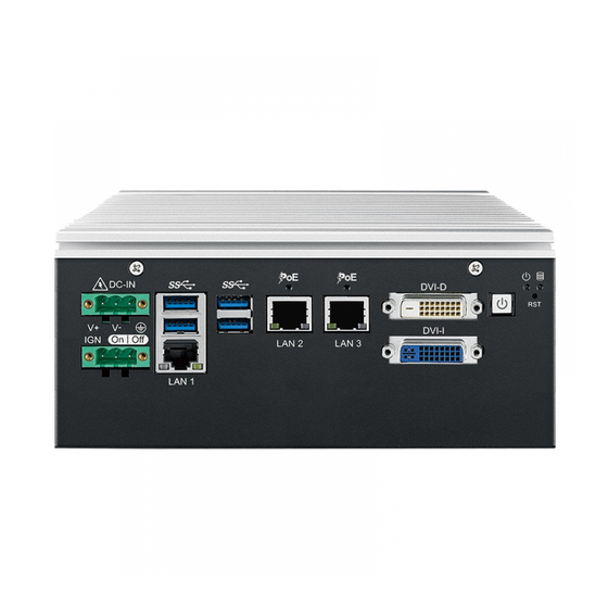
Page 25: Front Panel I/O & Functions
2.2 Front Panel I/O & Functions In Vecow ARS-2000 series, it has 3-side of the I/O connectors which located on front, top and bottom panels. Most of the general connections to computer device, such as USB, DVI, LAN Jack and PoE ports, are placed on the front panel. - Page 26 It is a hardware reset switch. Please use this switch to reset ARS-2000 without power off. Press the Reset Switch for a few seconds, and then reset will be enabled. 2.2.2 PWR & HDD LED Indicator DC-IN DVI-D DVI-I On | Off...
-
Page 27: Power Button
S3, S5 Suspend to RAM, System off with standby power To power on ARS-2000, please press the power button and then the blue LED is lightened. To power off the system, you can either command shutdown by OS operation, or just simply press the power button. - Page 28 LAN 2 LAN 3 LAN 1 ARS-2000 supports 6V to 36V DC power input by terminal block on the front side. In normal power operation, power LED lightens in solid green. (Onboard LTC4356 supports up to 80V surge protection.) Pin No.
- Page 29 You could turn on or off the system power by using this contact. This terminal block supports dual function of soft power-on/power-off (instant off or delay 4 second), and suspending modes. Pin No. Definition Ignition (IGN) S/W + S/W - ©Vecow ARS-2000 User Manual GETTING TO KNOW YOUR ARS-2000...
- Page 30 The DVI is automatically selected according to the connected display. You will need a DVI-D cable when connecting to a display device. 2.2.7 DVI-I Connector DC-IN DVI-D DVI-I On | Off LAN 2 LAN 3 LAN 1 GETTING TO KNOW YOUR ARS-2000...
- Page 31 If using VGA function, you will need a DVI-I to VGA dongle connected to DVI-I device. Below is the DVI-I to VGA dongle image : 2.2.8 USB 3.0 DC-IN DVI-D DVI-I On | Off LAN 2 LAN 3 LAN 1 ©Vecow ARS-2000 User Manual GETTING TO KNOW YOUR ARS-2000...
-
Page 32: Ethernet Port
There are 4 USB 3.0 connections available supporting up to 5GB per second data rate in the front side of ARS-2000. It is also compliant with the requirements of Super Speed (SS), High Speed (HS), Full Speed (FS) and Low Speed (LS). - Page 33 LAN 2 LAN 3 LAN 1 There are 2 RJ45 connectors or 2 M12 connectors on the front side of ARS-2000. It supports IEEE 802.3at (PoE ) Power over Ethernet (PoE) connection delivering up to 37W/54V per port and 1000BASE-T GigE data signals over standard ®...
- Page 34 Ethernet data packets are being transmitted/received. 10Mbps 100Mbps 1000Mbps Right Solid Solid Bottom LED Green Orange Left Flash Flash Flash Bottom LED Orange Orange Orange PoE LED indicator POE LED LED Color POE Status Solid Green POE ON GETTING TO KNOW YOUR ARS-2000...
-
Page 35: Top Panel I/O & Functions
• GB4943.1-2011 CQC Certified DIO Connectors pin out: Pin No. Definition Function INPUT 0 SIO_GPI80 INPUT 1 SIO_GPI81 INPUT 2 SIO_GPI82 DIO1 INPUT 3 SIO_GPI83 INPUT 4 SIO_GPI84 INPUT 5 SIO_GPI85 ©Vecow ARS-2000 User Manual GETTING TO KNOW YOUR ARS-2000... - Page 36 SIO_GPI64 INPUT 15 SIO_GPI65 DI2_COM DIO2 DIO2_GND OUTPUT 8 SIO_GPO11 OUTPUT 9 SIO_GPO12 OUTPUT 10 SIO_GPO15 OUTPUT 11 SIO_GPO16 OUTPUT 12 SIO_GPO32 OUTPUT 13 SIO_GPO33 OUTPUT 14 SIO_GPO35 OUTPUT 15 SIO_GPO36 DIO2_GND DIO2_VDC (6~48V Input) GETTING TO KNOW YOUR ARS-2000...
- Page 37 Sink Mode Device DIO Connector (NPN, Default) 6-48V DC DIO_VDC (Pin 20) DO (Pin11-18) DIO_GND (Pin10,19) Source Mode Device DIO Connector (PNP) 6-48V DC DIO_VDC (Pin 20) DO (Pin11-18) DIO_GND (Pin10,19) ©Vecow ARS-2000 User Manual GETTING TO KNOW YOUR ARS-2000...
-
Page 38: Audio Jack
PIN 11 ~ 18 PIN 1 ~ 8 PIN 11 ~ 18 There are 2 audio connectors, Mic-in and Line-out, on the top side of ARS-2000. Onboard Realtek ALC892 audio codec supports 5.1 channel HD audio and fully ® complies with Intel High Definition Audio (Azalia) specifications. -
Page 39: Bottom Panel I/O & Functions
Port (5-wire) (9-wire) (3-wire) TXD- TXD- DATA- TXD+ TXD+ DATA+ RXD+ RXD+ ----------- RXD- RXD- ----------- 1 to 4 ----------- RTS- ----------- ----------- RTS+ ----------- ----------- CTS+ ----------- ----------- CTS- ----------- ©Vecow ARS-2000 User Manual GETTING TO KNOW YOUR ARS-2000... - Page 40 COM 1 to COM 4 MB connector pin out: Pin No. Signal Name Chassis GND CN 9 (COM 3) CN 10 (COM 4) BIOS Setting Function RS-232 RS-422 (5-wire) COM 1 RS-422 (9-wire) COM 2 RS-485 RS-485 w/ auto-flow control GETTING TO KNOW YOUR ARS-2000...
- Page 41 COM Port MB Connector COM 1 JCOM1 COM 2 JCOM2 COM 1 to COM 2 MB connector pin out: Pin No. Signal Name Chassis GND JCOM1 (COM 1) JCOM2 (COM 2) ©Vecow ARS-2000 User Manual GETTING TO KNOW YOUR ARS-2000...
- Page 42 It is implemented by a SATA III Port from PCH. Be sure to disconnect the power source and unscrew the CFast socket cover before installing a CFast card. ARS-2000 does not support the CFast hot swap and PnP (Plug and Play) functions. It is necessary to remove power source first before inserting or removing the CFast card.
- Page 43 Mini PCIe Slot/SIM Slot Mapping Table: Mini PCIe Mini PCIe 1/ mSATA (CN13) Mini PCIe 2 (CN14) SIM (CN15) Mini PCIe 1/mSATA Select SW: Jumper (JP4) Interface Auto Detection Mini PCIe mSATA ©Vecow ARS-2000 User Manual GETTING TO KNOW YOUR ARS-2000...
-
Page 44: Main Board Expansion Connectors
2.5 Main Board Expansion Connectors 2.5.1 Top View of ARS-2000 Main Board with Connector Location JP11 CN13 SODIMM2 CN33 SODIMM1 FAN1 JP80 USB2_1 USB2_2 JCOM3 JCOM2 CN14 JCOM4 JCOM1 GETTING TO KNOW YOUR ARS-2000... - Page 45 2.5.2 Bottom View of ARS-2000 Main Board with Connector Location 2.5.3 Miscellaneous Header This Header can be used as a backup for following functions, such as hard drive LED indicator, reset button, power LED indicator, and power-on/off button, which already can be accessed by front panel and top panel. The pin-outs of Miscellaneous port are listed in following table: ©Vecow ARS-2000 User Manual...
- Page 46 PWR_LED_N FP_PWR_BTN_IN POWER BUTTON 2.5.4 DDR4 Slot SODIMM2 SODIMM1 There are 2 DDR4 channels onboard supporting DDR4 2133/1866 and up to 32GB. (Each channel 16GB) Slot Description SODIMM_1 DDR4 Channel A SODIMM_2 DDR4 Channel B GETTING TO KNOW YOUR ARS-2000...
- Page 47 Description 2.5.6 SATA Power Header ARS-2000 is also equipped with 1 SATA power connector. It supports 5V (Up to 2A) and 12V (Up to 1A) current to the hard drive or SSD. The pin assignments of J3 is listed in the following table: Pin No.
- Page 48 1. When a Mini PCIe device is inserted, its pin-43 forces the respective pin on the socket to ground, or logic 0. ARS-2000 using JP4 Pin-43 status designed for switching between mSATA drive and Mini PCIe device.
- Page 49 Reserved +V3P3aux USB_D+ USB_D- PETp0 PETn0 SMB_DATA SMB_CLK +1.5V PERp0 PERn0 +V3P3aux PERST# Reserved reserved Reserved Mechanical Key UIM_VPP REFCLK+ UIM_RESET REFCLK- UIM_CLK UIM_DATA CLKREQ# UIM_PWR Reserved 1.5V Reserved WAKE# 3.3Vaux ©Vecow ARS-2000 User Manual GETTING TO KNOW YOUR ARS-2000...
- Page 50 Pin No. function Reserved +V3P3aux Reserved Reserved +1.5V Reserved Reserved Reserved +V3P3aux Reserved +V3P3aux USB_D+ USB_D- PETp0 PETn0 SMB_DATA SMB_CLK +1.5V PERp0 PERn0 +V3P3aux PERST# Reserved reserved Reserved Mechanical Key UIM_VPP REFCLK+ UIM_RESET REFCLK- UIM_CLK UIM_DATA GETTING TO KNOW YOUR ARS-2000...
- Page 51 3.3Vaux 2.5.8 RTC Battery ARS-2000 real-time clock is powered by a lithium battery. It is equipped with Panasonic BR2032 190mAh lithium battery. It is recommended that do not replace the lithium battery on your own. If the battery need to be changed, please contact the Vecow RMA service team.
- Page 52 2.5.12 Internal USB 2.0 USB2_1 USB2_2 ARS-2000 main board provides 4 expansion USB ports using plug-and-play for Dongle Key. The USB interface supports 480 Mbps transfer rate complied with high speed USB specification Rev. 2.0. The USB interface is accessed through two 10-pin JST 1.0mm connectors. You will need an adapter cable if you use a standard USB connector.
-
Page 53: Main Board Jumper & Deep Switch Settings
CN14 JCOM4 JCOM1 The figure below is the top view of ARS-2000 board, and it shows the location of the jumpers and the switches. You may configure your card to match the needs of your application by setting jumpers. A jumper is a metal bridge used to close an electric circuit. It consists of two metal pins and a small metal clip (often protected by a plastic cover) that slides over the pins to connect them. - Page 54 +5V (1A max.) COM2 +12V (0.5A max.) RI (Default) Pin Header Pin No. Description +5V (1A max.) COM3 +12V (0.5A max.) RI (Default) Pin Header Pin No. Description +5V (1A max.) COM4 +12V (0.5A max.) RI (Default) GETTING TO KNOW YOUR ARS-2000...
- Page 55 PoE power on after system power on (Default) 2.6.4 SATAIII & mSATA Select Jumper Pin No. Function 1 - 2 Spport on board SATA III 3 - 4 Spport mSATA interface for Mini PCIe 1 (CN13) ©Vecow ARS-2000 User Manual GETTING TO KNOW YOUR ARS-2000...
- Page 56 2.6.5 USB Power Jumper Jumper Pin No. Function 1 - 2 Supported Wake Up (Default) 2 - 3 Non Wake Up support 2.6.6 Clear ME/CMOS Jumper Pin No. Function +V3P3 (Default) JP2 (CMOS)/ JP3 (ME) GETTING TO KNOW YOUR ARS-2000...
-
Page 57: Ignition Control
2.6.7 MCU Spy-bi Wire Interface for Download FW The pin assignments of J8 are listed in the following table: Pin No. Function Pin No. Function 3.3V_MCU MCU_RST# MCU_PRG 2.7 Ignition Control ©Vecow ARS-2000 User Manual GETTING TO KNOW YOUR ARS-2000... - Page 58 2.7.1 Adjust Ignition Control Modes ARS-2000 series provides 16 modes of different power on/off delay periods adjustable via rotary switch. The default rotary switch is set to 0 in ATX/AT power mode. The modes are listed in below table:...
- Page 59 Ignition signal input (ACC power of vehicle) Note: 1. DC power source and IGN share the same ground. 2. ARS-2000 supports 6V to 36V wide range DC power input in ATX/AT mode. In Ignition mode, the input voltage is fixed to 12V/24V for car battery scenario.
- Page 60 When the system is running on a battery and its voltage drops below the threshold, the system will automatically shut down. The Low Battery Detection is implemented in the ignition control MCU FW and as a default function. Note: Battery Voltage Thresholds 10.5~15V 21.5~30V GETTING TO KNOW YOUR ARS-2000...
-
Page 61: Chapter 3 System Setup
SYSTEM SETUP 3.1 How to Open Your ARS-2000 Step 1 Remove four F-M3x4 screws. Step 2 Open this cover and removed SATA and SATA Power cable. ©Vecow ARS-2000 User Manual HARDWARE INSTALLATION... - Page 62 Step 3 Remove three PH-M3x6L screws. Step 4 Finish. HARDWARE INSTALLATION...
-
Page 63: Installing Ddr4 So-Dimm Module
3.2 Installing DDR4 SO-DIMM Module Step 1 Install DDR4 RAM module into SO-DIMM slot. Step 2 Make sure RAM module is locked by the memory slot. ©Vecow ARS-2000 User Manual HARDWARE INSTALLATION... -
Page 64: Installing Mini Pcie Card
3.3 Installing Mini PCIe Card Step 1 Install Mini PCIe card into the Mini PCIe slot. Step 2 Fasten one M2.5 screw. HARDWARE INSTALLATION... -
Page 65: Installing Antenna Cable
3.4 Installing Antenna Cable Step 1 Remove plug. Step 2 Prepare your Antenna cable, washer, nut. Step 3 Put Antenna cable connector into panel. Put on washer and fasten nut. Step 4 Finish. ©Vecow ARS-2000 User Manual HARDWARE INSTALLATION... -
Page 66: Installing Cfast Card
3.5 Installing CFast Card Step 1 Remove two M3x4L screws on the cover. Step 2 CFast card slot. Step 3 Insert CFast card push to lock. HARDWARE INSTALLATION... -
Page 67: Installing Sim Card
3.6 Installing SIM Card Step 1 Remove two M3x4L screws on the cover. Step 2 SIM card slot. Step 3 Insert SIM card push to lock. ©Vecow ARS-2000 User Manual HARDWARE INSTALLATION... -
Page 68: Installing Ssd/Hdd
3.7 Installing SSD/HDD Step 1 Install SSD/HDD with HDD bracket. Step 2 Lock M3 screws. (one SSD/HDD with four M3 screws) Step 3 Finish locked screws. Step 4 Install SATA, power SATA cable with SSD/HDD and fasten three M3x6 screws. HARDWARE INSTALLATION... -
Page 69: Installing Pci/Pcie Card (Not For Light Version)
3.8 Installing PCI/PCIe Card (NOT for LIGHT version) Step 1 Remove the bottom cover. Step 2 Remove one M3 screw with Add-on-card bracket. ©Vecow ARS-2000 User Manual HARDWARE INSTALLATION... - Page 70 Step 3 Install PCIe/PCI card to the socket. Step 4 Fasten the M3 screw. HARDWARE INSTALLATION...
-
Page 71: Mounting Your Ars-2000
3.9 Mounting Your ARS-2000 3.9.1 Wall Mount (Default) Step 1 Fasten wall mount with ARS-2000. Step 2 Fasten four F-M3x4L screws. Step 3 Finish. ©Vecow ARS-2000 User Manual HARDWARE INSTALLATION... - Page 72 3.9.1 Din Rail Kit Step 1 Fasten DIN Rail Kit with ARS-2000. Step 2 Fasten four F-M3x4L screws. Step 3 Finish. HARDWARE INSTALLATION...
-
Page 73: Chapter 4 Bios Setup
Figure 4-1: Entering Setup Screen BIOS provides an interface for users to check and change system configuration. The BIOS setup program is accessed by pressing the <Del> key when POST display output is shown. ©Vecow ARS-2000 User Manual BIOS AND DRIVER SETTING... -
Page 74: Main
4.2 Main Figure 4-2: BIOS Main Menu The main menu displays BIOS version and system information. There are two options on the main menu, system date and system time. System Date Set the date. Use <Tab> to switch between date elements. System Time Set the time. -
Page 75: Trusted Computing
Selects the highest ACPI sleep state the system will enter when the SUSPEND button is pressed. S3 Video Repost Enables or disables S3 video repost. ACPI Low Power S0 Idle Enables or disables ACPI low power S0 idle support. ©Vecow ARS-2000 User Manual BIOS AND DRIVER SETTING... -
Page 76: Amt Configuration
4.3.3 AMT Configuration Figure 4 3-3: Intel AMT Settings Intel AMT Enables/disables Intel (R) Active Management Technology BIOS extension. Note: iAMT H/W is always enabled. This option just controls the BIOS extension execution. If enabled, this requires additional firmware in the SPI device. 4.3.4 PCH-FW Configuration Figure 4 3-4: PCH-FW Settings ME Unconfig on RTC Clear State... - Page 77 Set parameters of serial port 2 (COM2). Serial Port 3 Configuration (NOT for LIGHT version) Set parameters of serial port 3 (COM3). Serial Port 4 Configuration (NOT for LIGHT version) Set parameters of serial port 4 (COM4). ©Vecow ARS-2000 User Manual BIOS AND DRIVER SETTING...
-
Page 78: Hardware Monitor
4.3.7 Hardware Monitor Figure 4 3-7: Hardware Monitor Settings The IT8786 SIO features an enhanced hardware monitor providing thermal, fan speed, and system voltages' status monitoring. 4.3.8 Serial Port Console Redirection Figure 4 3-8: Serial Port Console Redirection Settings Console Redirection Console redirection enable or disable. - Page 79 Enable/disable CPU Advanced Encryption Standard instructions. Boot performance mode Select the performance state that the BIOS will set before OS handoff. Intel(R) SpeedStep(tm) Allows more than two frequency ranges to be supported. ©Vecow ARS-2000 User Manual BIOS AND DRIVER SETTING...
- Page 80 Turbo Mode Turbo Mode. CPU C state Enable or disable CPU C states. Enhanced C-states Enable/disable C1E. When enabled, CPU will switch to minimum speed when all cores enter C-State. Package C State limit Package C State limit. Intel TXT(LT) Support Enables or disables Intel (R) TXT (LT) support.
- Page 81 Indicates the maximum speed the SATA controller can support. Options for each SATA port Port 0 Enable or disable SATA Port. SATA Device Type Identifies that the SATA port is connected to solid state drive or hard disk drive. ©Vecow ARS-2000 User Manual BIOS AND DRIVER SETTING...
- Page 82 4.3.12 Acoustic Management Configuration Figure 4 3-12: Acoustic Management Settings Acoustic Management Configuration Option to enable or disable automatic acoustic management. 4.3.13 CSM Configuration Figure 4 3-13: CSM Settings BIOS AND DRIVER SETTING...
- Page 83 Controls the execution of UEFI and Legacy Storage OpROM. Video Allows more than two frequency ranges to be supported. Other PCI devices Determines OpROM execution policy for devices other than network, storage, or video. ©Vecow ARS-2000 User Manual BIOS AND DRIVER SETTING...
- Page 84 4.3.14 USB Configuration Figure 4 3-14: USB Settings Legacy USB Support Enables Legacy USB support. AUTO option disables Legacy support if no USB devices are connected. DISABLE option will keep USB devices available only for EFI applications. XHCI Hand-off This is a workaround for OS-es without XHCI hand-off support. The XHCI ownership change should be claimed by XHCI driver.
-
Page 85: Chipset
VT-d VT-d capability. GMM Device (B0:D8:F0) Enable/disable SA GMM device. Above 4GB MMIO BIOS assignment Enable/disable above 4GB MemoryMappedIO BIOS assignment. This is disabled automatically when aperture size is set to 2048MB. ©Vecow ARS-2000 User Manual BIOS AND DRIVER SETTING... -
Page 86: Graphics Configuration
4.4.2 Graphics Configuration Figure 4-4-2: Graphics Settings Skip Scaning of External Gfx Card If Enable, it will not scan for External Gfx Card on PEG and PCH PCIE Ports. Primary Display Select which of IGFX/PEG Graphics device should be Primary Display. Internal Graphics Keep IGFX enabled based on the setup options. - Page 87 Specify what state to go to when power is re-applied after a power failure (G3 state). S0 State: Always turn-on the system when power source plugged-in. S5 State: Always turn-off the system when power source plugged-in. ©Vecow ARS-2000 User Manual BIOS AND DRIVER SETTING...
- Page 88 4.4.5 PCI Express Configuration Figure 4-4-5: PCH-IO Settings DMI Link ASPM Control Enable/disable the control of active state power management on SA side of the DMI link. Native PCIE Enable PCI Express Native Support Enable/Disable. This feature is available in vista and beyond Windows OS.
-
Page 89: Security
Both: Run the Legacy Option ROM and UEFI driver. 4.4.8 DVI-I Port Configuration Figure 4-4-8: DVI-I DDC settings DDC Signal Selection VGA/DVI ports DDC selection. 4.5 Security Figure 4-5: BIOS Security Settings ©Vecow ARS-2000 User Manual BIOS AND DRIVER SETTING... -
Page 90: Administrator Password
Administrator Password Set administrator password. User Password Set user password. 4.5.1 HDD Security Configuration Figure 4-5-1: HDD Security Settings Set User Password Set HDD user password. *** Advisable to power cycle system after setting hard disk passwords ***. Discard or save changes option in setup does not have any impact on HDD when password is set or removed. -
Page 91: Boot
Sets the system boot order. New Boot Option Policy Controls the placement of newly detected UEFI boot options. Hard Drive BBS Priorities Set the order of the Legacy devices in this group. ©Vecow ARS-2000 User Manual BIOS AND DRIVER SETTING... -
Page 92: Save & Exit
4.7 Save & Exit Figure 4-7: Save & Exit Menu Save Changes and Exit Exit system setup after saving the changes. Discard Changes and Exit Exit system setup without saving any changes. Save Changes and Reset Reset the system after saving the changes. Discard Changes and Reset Reset system setup without saving any changes. -
Page 93: Appendix A : Isolated Dio Guide
APPENDIX A : Isolated DIO Guide A.1 Function Description The ARS-2000 offers two 16-bit (Isolated/Non-Isolated) 20-pin terminal block connector, a watchdog timer, and a 2-port POE Isolated DIO pins are fix by Hardware design that cannot change in/out direction in runtime process. DIO... - Page 94 POE definition is shown below : Do NOT use these functions in below: 1. PE-2000: DIO1 (ID = 0), POE 2. PE-3000: POE(ID=0) 3. UE-1000: USB (ID = 0) Pin No. Definition Pin No. Definition POE 0 POE 1 A.2 Isolated DIO Signal Circuit DI reference circuit: Sink Mode (NPN) Power...
- Page 95 Runtime folder include head file for software developer or System Integration. Sample folder include sample program, driver library, and API library. Source folder include sample program source code that compile on Visual Studio 2008. A.4 Function Description Demo tool (ARS2K.exe) Appendix A ©Vecow ARS-2000 User Manual...
- Page 96 DIO1 / DIO2 group: Isolate check button: DIO type of DIO configuration, isolated / non-isolated. Read button: Set DIO configuration to get DI / DIO input state. DO type check button: User setting, DO type of DIO configuration to setup 8 pins - Source / Sink. Use for Write (DO) button activate.
- Page 97 User setting, POE port writable of POE configuration. Use for Write button activate. POE port mode texts (port 2 ~ port 1): User setting, POE port mode of POE configuration. Use for Write button activate. Appendix A ©Vecow ARS-2000 User Manual...
-
Page 98: Appendix B : Software Functions
APPENDIX B : Software Functions B.1 Driver API Guide In Runtime folder, on ARS2K.h : _DLL_IMPORT_ definition is used on LoadLibrary API for ARS2K.dll. ARS2K_EXPORTS definition is used on ARS2K.dll building. Otherwise, that is used to compile with ARS2K.lib BOOL Initial (BYTE Isolate_Type, BYTE DIO_NPN) Initial machine for DIO, watchdog timer, and POE Isolate_Type: DIO type 1: Isolated DIO;... - Page 99 FALSE (0): Fail (Initial error, or call by pointer error, or hardware problem) BOOL SetDO1(BYTE DO) BOOL SetDO2(BYTE DO) Set isolated DIO output (DO) DO ([7:0]): Output state, pin setting by hexadecimal bitmask 1: High; 0: Low Appendix B ©Vecow ARS-2000 User Manual...
- Page 100 Return: TRUE (1): Success; FALSE (0): Fail (Initial error, or hardware problem) BOOL GetDIO1(WORD *DI) BOOL GetDIO2(WORD *DI) Get non-isolated DIO input (DIO input) DI ([15:0]): Input state, pin setting by hexadecimal bitmask 1: High; 0: Low Return: TRUE (1): Success; FALSE (0): Fail (Initial error, or call by pointer error, or hardware problem) BOOL SetDIO1(WORD DO) BOOL SetDIO2(WORD DO)
- Page 101 BOOL SetPOE(BYTE POE) Set POE output POE ([1:0]): POE state, pin setting by hexadecimal bitmask 1: On; 0: Off Return: TRUE (1): Success; FALSE (0): Fail (Initial error, or out of range error, or hardware problem) Appendix B ©Vecow ARS-2000 User Manual...
-
Page 102: Appendix C : Raid Installation Guide
APPENDIX C : RAID Installation Guide C.1 RAID Functions C.1.1 SATA Mode for RAID Please select SATA device to RAID mode on BIOS menu. Advanced → SATA Configuration → SATA Mode Selection → RAID (Skylake platform) / Intel RST Premium (Kaby Lake platform) C.1.2 UEFI Mode for RAID 1. - Page 103 6. Select disks to create RAID Volume then Save Changes and Reset to install OS with EFI mode. C.2 OS Installation ARS-2000 is featured with two SATA, including two internal SATA. We used SATA for Windows 10 OS installation as an example. Appendix C...
- Page 104 Please note, you can use two SATA ports for SATA HDD, except for mSATA slot. C.6 Create RAID Volume on “Rapid Storage Technology” Software ARS-2000 is featured with two SATA HDD’s for RAID volume, so there are two options to choose on this page. Let’s take RAID 1 as an example, select ”RAID 1”...
- Page 105 Then add “Logical Device” for Windows access. C.8 If One SATA HDD on RAID Volume is Out-of-use After RAID 1 volume created, you can see the figure of SATA device allocation. HDD CAUTION Sign Appendix C ©Vecow ARS-2000 User Manual...
- Page 106 C.9 Recovery and Auto Re-build When Using the SAME RAID HDD C.10 Recovery and Auto Re-build When Using DIFFERENT RAID HDD There is a warning will pop-up to ask you if the disk is not a member of original RAID volume. If you press “Rebuild”, it will replace the broken SATA HDD to the last one SATA HDD of RAID volume.
-
Page 107: Appendix D : Power Consumption
MEMXPRO M3A 128GB SATA 0 MEMXPRO M3A 512GB LAN 1 (i219) 1.0 Gbps LAN 2 (i210) 1.0 Gbps LAN 2 (i210) 1.0 Gbps Graphics Output Power Plan Balance (Windows10 Power Plan) Power Source Chroma 62006P-100-25 Appendix D ©Vecow ARS-2000 User Manual... - Page 108 D.1 Intel® Core™ i7-6600U (4M Cache, 3.4 GHz) Power on and boot to Win 10 64-bit Idle Status : Sleep Mode CPU usage less 3% Power Input Current Consumption Current Consumption i7-6600U 0.519A 04.67W 1.542A 13.88W i7-6600U 0.454A 05.45W 1.118A 13.42W i7-6600U 0.230A...
- Page 109 Run 100% CPU usage without 3D usage with 3D Power Input Current Consumption Current Consumption i5-6300U 2.488A 22.39W 3.673A 33.06W i5-6300U 2.193A 26.32W 2.723A 32.68W i5-6300U 1.118A 26.83W 1.399A 33.58W i5-6300U 0.749A 26.96W 0.922A 33.17W Appendix D ©Vecow ARS-2000 User Manual...
- Page 110 D.3 Intel® Core™ Celeron® 3955U (2M Cache) Power on and boot to Win 10 64-bit Idle Status : Sleep Mode CPU usage less 3% Power Input Current Consumption Current Consumption ® Celeron 0.531A 04.78W 1.298A 11.68W 3955U ® Celeron 0.458A 05.50W 1.053A 12.64W...
-
Page 111: Appendix E : Supported Memory & Storage List
ARS-2000 i7-6600U Memory Test version: 5.1 BurnInTest V8.1 E.2 Test Item Remove Channel Memory Test Burn In Flash BIOS Battery PASS PASS PASS PASS *1(Socket 1) PASS PASS PASS *1(Socket 2) PASS PASS PASS Appendix E ©Vecow ARS-2000 User Manual... - Page 112 E.3 NON-ECC Test Temp. Brand Info Channel NOTE & S\N (Celsius) KVR21S15D8/16 25ºC 16GB 2Rx8 Kingston 2Gx64-Bit *1(Socket 1) BKMM1641607 25ºC PC4-2133 *1(Socket 2) BKMM1661618 25ºC D4S4GHIOFEI 25ºC DDR4- Memxpro *1(Socket 1) 01611170040001 25ºC 2133-15 Wild Temp. *1(Socket 2) 01611170040002 25ºC D4S8GHIOFFI 25ºC...
- Page 113 SATA SSD SSD M3A MI3MA1251208WN 512GB MEMXPRO SSD Lite M3B MI3MB0132G02SN-AH 32GB SSD Lite M3B MI3MB1112802SN-AH 128GB SSD Lite M3B MI3MB1125604WN 256GB ** If more help is needed, please contact Vecow technical support ** Appendix E ©Vecow ARS-2000 User Manual...
- Page 114 No part of this publication may be reproduced in any form or by any means, electric, photocopying, or recording, without prior authorization from the publisher. The rights of all the brand names, product names, and trademarks belong to their respective owners. © Vecow Co., Ltd. 2017. All rights reserved.
Need help?
Do you have a question about the ARS-2000 and is the answer not in the manual?
Questions and answers