
Related Manuals for Vecow EAC-5000


Summary of Contents for Vecow EAC-5000
- Page 1 USER USER EAC-5000 Manual Manual NVIDIA ® Jetson AGX Orin ™ Edge AI Computing System 6 GigE LAN with 4 PoE , 8 GMSL2, 1 PCIe x8, -25°C to 70°C Operation 1.0.0 Edition 20230817...
- Page 2 Record of Revision Version Date Remark Page Description 1.00 2023/8/17 Official Release ©Vecow EAC-5000 User Manual...
- Page 3 This manual is released by Vecow Co., Ltd. for reference purpose only. All product offerings and specifications are subject to change without prior notice. It does not represent commitment of Vecow Co., Ltd. Vecow shall not be liable for direct, indirect, special, incidental, or consequential damages arising out of the use of the product or documentation or any infringements upon the rights of third parties, which may result from such use.
- Page 4 Order Information Part Number Description EAC-5000, on-board 64GB RAM, 2 LAN, 5 USB 3.1, 2 COM RS- EAC-5000-R64 232/422/485, 2 Isolated CAN Bus, 16 Isolated DIO, 1 PCIe Gen4 x8, 8 Fakra-Z connectors for GMSL 1/2 automotive cameras EAC-5000, on-board 32GB RAM, 2 LAN, 5 USB 3.1, 2 COM RS-...
- Page 5 GMSL Camera with Fakra-Z connector M.2 Storage Module M.2 Key M/Key B PCIe Storage Module 5G Module 5G Module with Antenna 4G Module 4G/GPS Module with Antenna WiFi & Bluetooth Module WiFi & Bluetooth Module with Antenna ©Vecow EAC-5000 User Manual...
-
Page 6: Table Of Contents
2.4 Main Board Connector & Jumper Locations 2.5 Main Board Jumper Settings 2.6 Ignition Control CHAPTER 3 SYSTEM SETUP 3.1 How to Open Your EAC-5000/EAC-5100 3.2 Installing Nano SIM Card 3.3 Installing Micro SD Card 3.4 Installing PCIe Card 3.5 Installing M.2 3.6 Installing Antenna Cable... - Page 7 CHAPTER 4 SOFTWARE SETUP 4.1 Peripheral Interface Guide 4.2 Flash image to Your EAC-5000/EAC-5100 4.3 Software Ignition Control APPENDIX A : GMSL Camera Guide(EAC-5000 Only) APPENDIX B : Power Consumption APPENDIX C : Supported Expansion Module List ©Vecow EAC-5000 User Manual...
-
Page 8: Chapter 1 General Introduction
5100-OOB. The EAC-5000-OOB and EAC-5100-OOB models are integrated with OOB (Out-of-Band) remote management operation technology, bringing powerful disaster recovery service to Edge AI applications. The Vecow EAC-5000/5100 is based on the NVIDIA Jetson AGX Orin platform, ® ® which features an Arm... -
Page 9: Features
• 6 GigE LAN with 4 PoE+, 1 Digital Display supports 4K60 • 2 Isolated CAN Bus support Flexible Data-rate, 2 COM RS-232/422/485, 5 USB 3.1 • Supports device remote management by Allxon • DC 9V to 50V wide range power input, Ignition Power Control ©Vecow EAC-5000 User Manual GENERAL INTRODUCTION... -
Page 10: Product Specification
1.3 Product Specification 1.3.1 Specifications of EAC-5000 System ® NVIDIA Jetson AGX Orin™ System-On-Module ® ® • 12-core Arm Cortex -A78AE v8.2 64-bit CPU Processor • 2048-core NVIDIA Ampere™ architecture GPU with 64 Tensor Cores R32 : 1 32GB LPDDR5 DRAM... - Page 11 -40°C to 85°C (-40°F to 185°F) Humidity 5% to 95% Humidity, non-condensing Relative Humidity 95% at 70°C Shock Operating, MIL-STD-810G, Method 516.7, Procedure I Operating, MIL-STD-810G, Method 514.7, Procedure I, Vibration Category 4 CE, FCC, EN50155, EN50121-3-2, EN62368-1 ©Vecow EAC-5000 User Manual GENERAL INTRODUCTION...
-
Page 12: Specifications Of Eac-5000-Oob
1.3.2 Specifications of EAC-5000-OOB System ® NVIDIA Jetson AGX Orin™ System-On-Module • 12-core Arm ® Cortex ® -A78AE v8.2 64-bit CPU Processor • 2048-core NVIDIA Ampere™ architecture GPU with 64 Tensor Cores R32 : 1 32GB LPDDR5 DRAM Memory R64 : 1 64GB LPDDR5 DRAM Storage eMMC 5.1, 64 GB... - Page 13 -40°C to 85°C (-40°F to 185°F) Humidity 5% to 95% Humidity, non-condensing Relative Humidity 95% at 70°C Shock Operating, MIL-STD-810G, Method 516.7, Procedure I Operating, MIL-STD-810G, Method 514.7, Procedure I, Vibration Category 4 CE, FCC, EN50155, EN50121-3-2, EN62368-1 ©Vecow EAC-5000 User Manual GENERAL INTRODUCTION...
-
Page 14: Specifications Of Eac-5100
• 1 Reset Button • 1 Micro USB console debug port Micro USB • 1 Micro USB OS flash port 2 SIM Card Socket Power, SSD, 2 User Programmable Antenna 6 Antenna for 5G/WiFi/4G/LTE/GPRS/UMTS ©Vecow EAC-5000 User Manual GENERAL INTRODUCTION... - Page 15 -40°C to 85°C (-40°F to 185°F) Humidity 5% to 95% Humidity, non-condensing Relative Humidity 95% at 70°C Shock Operating, MIL-STD-810G, Method 516.7, Procedure I Operating, MIL-STD-810G, Method 514.7, Procedure I, Vibration Category 4 CE, FCC, EN50155, EN50121-3-2, EN62368-1 ©Vecow EAC-5000 User Manual GENERAL INTRODUCTION...
-
Page 16: Specifications Of Eac-5100-Oob
• 1 Reset Button • 1 Micro USB console debug port Micro USB • 1 Micro USB OS flash port 2 SIM Card Socket Power, SSD, 2 User Programmable 2 OOB Status Antenna 6 Antenna for 5G/WiFi/4G/LTE/GPRS/UMTS ©Vecow EAC-5000 User Manual GENERAL INTRODUCTION... - Page 17 -40°C to 85°C (-40°F to 185°F) Humidity 5% to 95% Humidity, non-condensing Relative Humidity 95% at 70°C Shock Operating, MIL-STD-810G, Method 516.7, Procedure I Operating, MIL-STD-810G, Method 514.7, Procedure I, Vibration Category 4 CE, FCC, EN50155, EN50121-3-2, EN62368-1 ©Vecow EAC-5000 User Manual GENERAL INTRODUCTION...
-
Page 18: Mechanical Dimension
1.4 Mechanical Dimension 1.4.1 Dimensions of EAC-5000 308.2 (12.13) Unit : mm (inch) 286.4 (11.28) 260.0 (10.24) 1.4.2 Dimensions of EAC-5000-OOB Unit : mm (inch) 308.2 (12.13) 286.4 (11.28) 260.0 (10.24) ©Vecow EAC-5000 User Manual GENERAL INTRODUCTION... -
Page 19: Dimensions Of Eac-5100
1.4.3 Dimensions of EAC-5100 Unit : mm (inch) 308.2 (12.13) 286.4 (11.28) 260.0 (10.24) 1.4.4 Dimensions of EAC-5100-OOB Unit : mm (inch) 308.2 (12.13) 286.4 (11.28) 260.0 (10.24) ©Vecow EAC-5000 User Manual GENERAL INTRODUCTION... -
Page 20: Eac-5000/Eac-5100
GETTING TO KNOW YOUR EAC-5000/EAC-5100 2.1 Packing List Item Description EAC-5000/EAC-5100 Edge AI Computing System (According to the configuration of your order, EAC-5000/EAC-5100 series may contain micro SD and M.2 modules. Please verify these items if necessary.) Item Description Outlook... -
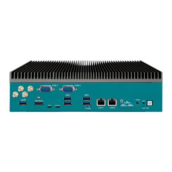
Page 21: Front Panel I/O & Functions
2.2 Front Panel I/O & Functions 2.2.1 Functions of EAC-5000/5100 series In Vecow EAC-5000 series, Most of the I/O connectors are located on the front panels. Most of the general connections to computer devices, such as COM, USB, LAN, Digital Display Port, Force Recovery button, Power Button,Reset Button, indicators are placed on the front panel. - Page 22 & releasing reset button while Recovery button is pressed. 2.2.1.4 Micro SD The external Micro SD card provides additional storage expansion. It is located behind the cover-plate on the front panel. ©Vecow EAC-5000 User Manual GETTING TO KNOW YOUR EAC-5000/EAC-5100...
- Page 23 2.2.1.5 Two Nano SIM The external Nano SIM card offers wireless communication capability to the system. ©Vecow EAC-5000 User Manual GETTING TO KNOW YOUR EAC-5000/EAC-5100...
- Page 24 2.2.1.6 Ethernet Port There are two 8-pin RJ-45 jacks supporting 10/100/1000 Mbps Ethernet connections on the front side of EAC-5000 series. It supports 1000BASE-T gigabit data signals over standard Ethernet Cat 5/Cat 6 cable. LAN Chip Function Connector RTL8211_LAN1 RJ-45(10/100/1000)
- Page 25 There are 4 USB 3.2 Gen1 connections available supporting up to 5Gb per second data rate in the front panel of EAC-5000 series. It is also compliant with the requirements of Super Speed (SS), High Speed (HS), Full Speed (FS) and Low Speed (LS).
- Page 26 ----------- ----------- ----------- ----------- ----------- ----------- ----------- ----------- ----------- ----------- 2.2.1.11 Console Port System debug Port,Micro USB to UART that connects to the SOM serial console. Pin No. Function USB_DATA- USB_DATA+ ©Vecow EAC-5000 User Manual GETTING TO KNOW YOUR EAC-5000/EAC-5100...
- Page 27 2.2.1.12 Flash Port The EAC-5000 USB Recovery mode provides an alternate boot device (USB). In this mode, the system is connected to a host system and boots over USB. This is used when a new image needs to be flashed. USB0 must be available to use as USB Device for USB Recovery Mode.
- Page 28 There are two Programmable LEDs,user can define the state of the led by himself. 2.2.1.16 OOB states LED indicator (EAC-5000-OOB/EAC-5100-OOB) The LED indicator can instantly judge the power status of OOB Enabler and the connection status of OOB Enabler and Allxon Portal. If both LEDs are on, it means OOB Enabler is running and the connection to Allxon Cloud is stable.
-
Page 29: Rear Panel I/O & Functions
2.3 Rear Panel I/O & Functions 2.3.1 Functions of EAC-5000 In Vecow EAC-5000 series, Some of the I/O connectors are located on the rear panels. Such as GMSL Camera, CAN Port, Power input, DIO Port indicators are placed on the rear panel. - Page 30 •CSA Component Acceptance Notice 5A, IEC 60950-1 and IEC 61010-1 End Equipment Standards •GB4943.1-2011 CQC Certified Pin No. Definition Function Pin No. Definition Function EXT_IN0 GPIO04 EXT_OUT0 GPIO25 EXT_IN1 GPIO11 EXT_OUT1 GPIO28 EXT_IN2 GPIO12 EXT_OUT2 GPIO31 EXT_IN3 GPIO14 EXT_OUT3 GPIO36 ©Vecow EAC-5000 User Manual GETTING TO KNOW YOUR EAC-5000/EAC-5100...
- Page 31 External Device DO Signal circuit in SINK mode (NPN) Source (PNP) DIO_VDC LOAD 7.2K ISOLATION (300mA) 1.5K GNDI GNDO GNDO Internal Circuit External Device GNDO DO Signal circuit in source mode (PNp) ©Vecow EAC-5000 User Manual GETTING TO KNOW YOUR EAC-5000/EAC-5100...
- Page 32 2.3.1.4 GMSL Camera Port There are eight FAKRA connectors in the rear side of EAC-5000. Each camera connects to the EAC-5000 through a single coax cable. Using GMSL2 (Gigabit Multimedia Serial Link) connections, the cameras are connected to a two-port deserializer.
- Page 33 The pin-outs of LAN 3~LAN 6 are listed as follows : Pin No. 10/100 Mbps 1000Mbps E_TX+ MDI0_P PoE+ E_TX- MDI0_N PoE+ E_RX+ MDI1_P PoE- ------ MDI2_P ------ ------ MDI2_N ------ E_RX- MDI1_N PoE- ------ MDI3_P ------ ------ MDI3_N ------ ©Vecow EAC-5000 User Manual GETTING TO KNOW YOUR EAC-5000/EAC-5100...
- Page 34 1000Mbps Ethernet network; The left LED will keep twinkling/off when Ethernet data packets are being transmitted/received. LED Location LED Color 10Mbps 100Mbps 1000Mbps Green/ Solid Solid Right Orange Green Orange Twinkling Twinkling Twinkling Left Orange Orange Orange Orange ©Vecow EAC-5000 User Manual GETTING TO KNOW YOUR EAC-5000/EAC-5100...
-
Page 35: Main Board Connector & Jumper Locations
CN18 CN22 CN21 CN17 CN16 CN26 CN25 CN32 SOM_FAN1 BAT2 M2B_CN1 JCOM2 M2E_CN1 JCOM1 JSPI1 SYS_FAN1 JAUDIO1 JIGNMODE1 CN13 CN28 CN12 CN10 CN11 BOT View of MB M2M_CN1 M2M_CN2 CN15 CN14 ©Vecow EAC-5000 User Manual GETTING TO KNOW YOUR EAC-5000/EAC-5100... - Page 36 2.4.1.1 CN32 Board to Board Connector to PoE LAN Board (PCIe x4) CN32 CN32 connector only apply to EAC-5000-PE board use. Host I/Fs supported PCIe x4 transfer 4 GigE with PoE LAN. 2.4.1.2 J4 IGNITION Control and Remote Power on switch Pin assignment as the following table : Pin No.
- Page 37 RS-422 or RS-485, you must change by software setting. Pin No. RS-232 RS-422 RS-485 (5-wire) (3-wire) ----------- ----------- ----------- ----------- ----------- ----------- ----------- RXD- ----------- ----------- ----------- RXD+ ----------- ----------- ----------- TXD+ DATA+ ----------- ----------- ----------- ----------- TXD- DATA- ©Vecow EAC-5000 User Manual GETTING TO KNOW YOUR EAC-5000/EAC-5100...
- Page 38 2.4.1.6 JSPI1 : SPI Connector JSPI1 Pin No. Definition P3.3V SPI1_MOSI_LS SPI1_MISO_LS SPI1_CS0_LS SPI1_SCK_LS SPI1_CS1_LS I2C4_SDA ------------- I2C4_SCL 2.4.1.7 J1 : Jetson AGX Orin SOM Socket Connection to Jetson AGX Orin SOM. ©Vecow EAC-5000 User Manual GETTING TO KNOW YOUR EAC-5000/EAC-5100...
- Page 39 Panasonic BR2032 190mAh lithium battery. It is recommended that you not replace the lithium battery on your own. If the battery needs to be changed, please contact the Vecow RMA service team. 2.4.1.9 M2B_CN1 : M.2 key B Slot for USB2.0,USB3.2 Gen1 support M2B_CN1 M.2 key B connector is suitable for applications that use Host I/Fs supported USB...
- Page 40 2.4.1.11 JAUDIO1 : Headphone Out and Microphone In Connector JAUDIO1 Pin No. Definition HPOUT_L HPOUT_R MIC_L MIC_R 2.4.1.12 SYS_FAN1 : System FAN Connector SYS_FAN1 Pin No. Definition +12V (1.0A max) ------- Fan PWM ©Vecow EAC-5000 User Manual GETTING TO KNOW YOUR EAC-5000/EAC-5100...
- Page 41 2.4.1.14 M2M_CN1/ M2M_CN2 : PCIe Gen3 x4 support M2M_CN1 M2M_CN2 M.2 key M connector is suitable for applications that use Host I/Fs supported PCIe x4, like w NVME Module card types include 2280. ©Vecow EAC-5000 User Manual GETTING TO KNOW YOUR EAC-5000/EAC-5100...
-
Page 42: Main Board Jumper Settings
2.5 Main Board Jumper Settings 2.5.1.1 Board Top View of EAC-5000 Main Board with Jumper. The figure below is the top view of EAC-5000 series main board which is the main board. It shows the location of the jumpers. JIGNMODE1 You may configure your card to match the needs of your application by setting jumpers. - Page 43 FAN Operation Voltage 12V(Default) 2.5.1.3 JP8: PoE Power On Select Mode Pin No. Definition POE Power On by P3.3V_SB (Default) POE Power On on by P3.3V 2.5.1.4 JP2 : COM2 RS485 Terminal resistance ON/OFF ©Vecow EAC-5000 User Manual GETTING TO KNOW YOUR EAC-5000/EAC-5100...
- Page 44 2.5.1.6 JIGNMODE1 : Ignition Mode Select JIGNMODE1 Pin No. Definition H/W MODE(Default) S/W MODE 2.5.1.7 JP4 : SYS_FAN1 Operation Voltage Select Pin No. Definition FAN Operation Voltage 5V FAN Operation Voltage 12V(Default) ©Vecow EAC-5000 User Manual GETTING TO KNOW YOUR EAC-5000/EAC-5100...
-
Page 45: Ignition Control
2.6.1 Adjust Ignition Control Modes EAC-5000 series provides 16 modes of different power on/off delay periods adjustable via SW6 switch. The default DIP switch is set to 0 in ATX power mode. SW6 : Ignition Control... - Page 46 Please find below the general wiring configuration. Pin No. Definition Ignition (IGN) For testing purpose, you can refer to the picture blow to simulate ignition signal input controlled by a latching switch. ©Vecow EAC-5000 User Manual GETTING TO KNOW YOUR EAC-5000/EAC-5100...
-
Page 47: Chapter 3 System Setup
SYSTEM SETUP 3.1 How to Open Your EAC-5000/EAC-5100 Step 1 Remove four I-M3x6L screws. Step 2 Pick up Heat Sink. ©Vecow EAC-5000 User Manual SYSTEM SETUP... -
Page 48: Installing Nano Sim Card
3.2 Installing Nano SIM Card Step 1 Remove one F-M3x4L screw on SD/SIM cover. Step 2 Inserting SIM card, make sure the system power is not plugged. ©Vecow EAC-5000 User Manual SYSTEM SETUP... -
Page 49: Installing Micro Sd Card
3.3 Installing Micro SD Card Step 1 Remove one F-M3x4L screw on SD/SIM cover. Step 2 Inserting SD card. ©Vecow EAC-5000 User Manual SYSTEM SETUP... -
Page 50: Installing Pcie Card
3.4 Installing PCIe Card Step 1 Remove two F-M3x4L screws on rear panel. Step 2 Pick up assembly Riser Card. ©Vecow EAC-5000 User Manual SYSTEM SETUP... - Page 51 Step 3 Remove the screw indicated and separate I/O bracket from assembly Riser Card. Step 4 Install PCIe card and fasten the screw indicated. ©Vecow EAC-5000 User Manual SYSTEM SETUP...
-
Page 52: Installing
3.5.1 M.2 Key E 2230 Step 1 Install M.2 Key E 2230 into slot and fasten one pan head M3x4L screw. 3.5.2 M.2 Key M 2280 Step 1 Remove two F-M3x4L screws on Storage cover. ©Vecow EAC-5000 User Manual SYSTEM SETUP... - Page 53 Step 2 Install M.2 Key M 2280 into slot and fasten one pan head M3x4L screw. 3.5.3 M.2 Key B 2242/3042 Step 1 Install M.2 Key B 2242/3042 into slot and fasten one pan head M3x4L screw. ©Vecow EAC-5000 User Manual SYSTEM SETUP...
- Page 54 3.5.4 M.2 Key B 3052 Step 1 Change the stud position. Step 2 Install M.2 Key B 3052 into slot and fasten one pan head M3x4L screw. ©Vecow EAC-5000 User Manual SYSTEM SETUP...
-
Page 55: Installing Antenna Cable
3.6 Installing Antenna Cable Step 1 Remove the rubber corks on the panel. Step 2 Put antenna cable connector into the hole on panel. Step 3 Fasten washer on the antenna cable connector. ©Vecow EAC-5000 User Manual SYSTEM SETUP... -
Page 56: Mounting Your Eac-5000/Eac-5100
3.7 Mounting Your EAC-5000/EAC-5100 3.7.1 Wall Mount Install wall mount bracket then fasten four pcs #6-32x6L screws. 3.7.2 VESA Mount Install VESA mount then fasten four pcs #6-32x6L screws. ©Vecow EAC-5000 User Manual SYSTEM SETUP... - Page 57 3.7.3 DIN Rail Mount Install din rail kit then fasten four pcs #6-32x6L screws. ©Vecow EAC-5000 User Manual SYSTEM SETUP...
-
Page 58: Chapter 4 Software Setup
For I/O support and example please follow this link: https://github.com/VecowSoftware/EAC-5000_IO_Sample 4.2 Flash image to Your EAC-5000/EAC-5100 Before starting the flashing process, be sure the EAC-5000 is turned off and disconnected from the power. You also need to prepare a host computer running Ubuntu 20.04 or later. - Page 59 4.2.3 Connect EAC-5000 to the host computer Step 1: Connect the power adapter to the EAC-5000. Connect the Micro USB cable to the “Flash” Port on EAC-5000 and the other end to an available USB port on the host PC. Make sure you have only ONE EAC-5000 device in recovery mode plugged in the host.
-
Page 60: Software Ignition Control
Step 4: Once the process finished, you should see the following log: 4.3 Software Ignition Control Vecow provides Ignition Software to control power on/off delay periods. To activte software ignition control, you need to adjust the JIGNMODE1 jumper to 2-3, you can access the following path: $ cd /usr/src/tools/EAC-5000/ignition/ https://github.com/VecowSoftware/EAC-5000_IO_Sample/tree/master/ignition... -
Page 61: Appendix A : Gmsl Camera Guide(Eac-5000 Only)
APPENDIX A : GMSL Camera Guide (EAC-5000 Only) Before you start Please connect the camera cable to GMSL port before power on the EAC-5000. To initialize the GMSL camera, you can access the following path $ cd /usr/src/tools/EAC-5000/camera/ https://github.com/VecowSoftware/EAC-5000_IO_Sample/tree/master/camera to find the camera initial scripts. -
Page 62: Appendix B : Power Consumption
64 GB eMMC 5.1 M.2 KEY E Intel 8265NGW LAN 1 1.0 Gbps LAN 2 1.0 Gbps Camera GMSL Camera 8pcs Graphics Output HDMI Power Plan 30W/MAXN Power Source Chroma 62006P-100-25 Test Program Stress-ng Test ©Vecow EAC-5000 User Manual Appendix B... - Page 63 Consumption 2.486A 22.37W 6.240A 56.16W 1.847A 22.16W 4.370A 52.44W ® 12-core Arm ® Cortex -A78AE v8.2 0.962A 23.10W 2.294A 55.06W 64-bit CPU, up to 2 GHz 0.679A 24.44W 1.556A 56.00W 0.530A 26.50W 1.201A 60.05W ©Vecow EAC-5000 User Manual Appendix B...
-
Page 64: Appendix C : Supported Expansion Module List
Global 5G coverage and LTE Cat. 20 fallback MV31-W GPS, Glonass, Beidou and Galileo C.2 Supported Wi-Fi/Bluetooth List Type Model Support Standard SparkLAN_WNFT- IEEE 802.11ac/a/b/g/n M.2 KEY E 237ACN(BT) BT5.0 IEEE 802.11a/b/g/n/ac M.2 KEY E Intel 8265NGW BT5.2 ©Vecow EAC-5000 User Manual Appendix C... - Page 65 No part of this publication may be reproduced in any form or by any means, electric, photocopying, or recording, without prior authorization from the publisher. The rights of all the brand names, product names, and trademarks belong to their respective owners. © Vecow Co., Ltd. 2023. All rights reserved.
Need help?
Do you have a question about the EAC-5000 and is the answer not in the manual?
Questions and answers