Table of Contents
Advertisement
Quick Links
Advertisement
Table of Contents

Related Manuals for Advantech EPC-U2117


Summary of Contents for Advantech EPC-U2117
- Page 1 User Manual EPC-U2117...
- Page 2 Because of Advantech’s high quality-control standards and rigorous testing, most of our customers never need to use our repair service. If an Advantech product is defec- tive, it will be repaired or replaced at no charge during the warranty period. For out- of-warranty repairs, you will be billed according to the cost of replacement materials, service time and freight.
- Page 3 This device complies with Part 15 of the FCC Rules. Operation is subject to the fol- lowing two conditions: (1) This device may not cause harmful interference, and (2) This device must accept any interference received, including interference that may cause undesired operation. EPC-U2117 User Manual...
- Page 4 Technical Support and Assistance Visit the Advantech web site at www.advantech.com/support where you can find the latest information about the product. Contact your distributor, sales representative, or Advantech's customer service center for technical support if you need additional assistance. Please have the following information ready before you call: –...
- Page 5 Antenna Cable SMA (F) to MHF 1.32 25cm For LTE Antenna Part Number Description Note 1750008717-01 Dipole Ant. D.B 2.4/5G WIFI 3dBi SMA/M-R BLK For WiFi 1750007990-01 Antenna 4G/LTE full band L=11 cm 50 Ohm For LTE EPC-U2117 User Manual...
- Page 6 Replacement of a BATTERY with an incorrect type that can defeat a SAFE- GUARD (for example, in the case of some lithium BATTERY types); Disposal of a BATTERY into fire or a hot oven, or mechanically crushing or cutting of a BATTERY, that can result in an EXPLOSION; EPC-U2117 User Manual...
- Page 7 L'utilisateur Si l'une des situations suivantes se présente, faites vérifier l'équipement par le personnel de service: Le cordon d'alimentation ou la fiche est endommagé. Le liquide a pénétré dans l'équipement. EPC-U2117 User Manual...
- Page 8 645 du Code national de l'électricité et à la norme NFPA 75 AVIS DE NON-RESPONSABILITÉ: Cet ensemble d'instructions est conforme à la norme CEI 704-1. Advantech décline toute responsabilité concernant l'exacti- tude des déclarations contenues dans ce document. EPC-U2117 User Manual...
-
Page 9: Table Of Contents
2.2.28 CPU FAN connector (CPUFAN1) ..........22 2.2.29 DDR3L SO-DIMM socket (DIMMA1) .......... 22 2.2.30 CPU-system on chip (SOC1) ............22 2.2.31 BIOS flash (SPI1)................ 23 Jumper List....................23 Chapter Peripheral Installation .......25 HDD Installation ..................26 Mini PCIe Module Installation..............27 EPC-U2117 User Manual... - Page 10 Chapter BIOS Setup ........29 BIOS Setup ..................... 30 Entering Setup ..................31 4.2.1 Main setup .................. 31 4.2.2 Advanced BIOS features setup ..........32 4.2.3 Chipset..................52 4.2.4 Security boot................59 4.2.5 Save & exit.................. 61 EPC-U2117 User Manual...
-
Page 11: Chapter 1 Introduction
Chapter Introduction This chapter briefly introduces the EP-U2117 product... -
Page 12: Overview
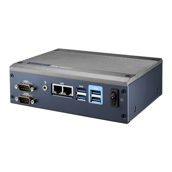
Overview The Advantech EP-U2117 is a palm-sized system using the latest Intel Atom E3900 processor technology to deliver a 30% CPU performance enhancement and a 45% graphics performance boost. EPC-U2117 is designed with dual display output, multi- ple I/O, and wide ranging 12-24V DC power inputs. It targets smart vending machines, digital signage, smart kiosks, and more. -
Page 13: General Specifications
Palm-sized, with extended temperature support under -20 ~ 60 °C Supports Win10 Enterprise 64-bit, Linux OS Advantech WISE-PaaS/DeviceON SW built-in Certificated with AWS Greengrass & Microsoft Azure IoT Edge 1.3.2 Power environment Power adaptor: AC/DC –... -
Page 14: Mechanical Specifications
Storage Temperature: -40~85° C Relative Humidity: 40 ~ 95% RH (Non-condensed) Safety CE/CCC/BSMI FCC class B approved for USA, Canada, and EU Vibration: With SSD: 3Grms, 60068-2-64, random, 5 ~ 500 Hz, 1 hr/axis EPC-U2117 User Manual... -
Page 15: Jumper And Connector List
Chapter Jumper and Connector List... -
Page 16: Jumper And Connector List
Jumper and Connector List (10) (11) (12) (27) (13) (22) (23) (14) (24) (15) (25) (16) (26) (17) (18) (20) (21) (19) Figure 2.1 Top View EPC-U2117 User Manual... -
Page 17: Figure 2.2 Bottom View
(14) Low pin count header (LPC1) (15) SPI programming pin header (SPI_CN1) (16) CMOS battery connector (BAT1) (17) General purpose I/O pin header (GPIO1) (18) COMS mode selection (JCMOS1) (19) AT/ATX mode selection (PSON1) (20) Serial bus header (JFP2) EPC-U2117 User Manual... -
Page 18: Connectors
(26) MINIPCIE and mSATA connector (MINI-PCIE1) (27) Next Generation form factor (M.2_1) (28) CPU FAN connector (CPUFAN1) (29) DDR3L SO-DIMM socket (DIMMA1) (30) CPU-System on chip (SOC1) (31) BIOS flash(SPI1) Connectors 2.2.1 DC input connector (DCIN1) Signal Power input EPC-U2117 User Manual... -
Page 19: High Definition Multimedia Interface (Hdmi1)
High definition multimedia interface (HDMI1) Signal Signal HDMI1_Z_D2+ HDMI1_Z_CLK- HDMI1_Z_D2- HDMI1_Z_D1+ HDMI1_SCL HDMI1_Z_D1- HDMI1_SDA HDMI1_Z_D0+ +V5_HDMI HDMI1_Z_D0- HDMI1_HPD HDMI1_Z_CLK+ 2.2.3 Display port (DP1) Signal Signal DP1_0+ DP1_3- DP1_0- DP1_AUX_EN# DP1_1+ DP1_AUX+ DP1_1- DP1_2+ DP1_AUX- DP1_DP_HPD DP1_2- DP1_3+ +V3.3_DP1 EPC-U2117 User Manual... -
Page 20: Hd Analog Audio Interface (Audio1)
2.2.4 HD analog audio interface (AUDIO1) Signal Line_L Detect Line_R 2.2.5 Single port RJ45 connector (LAN1) Signal Signal LAN1_MDI0+ LAN1_MDI2- LAN1_MDI0- LAN1_MDI3+ LAN1_MDI1+ LAN1_MDI3- LAN1_MDI1- LAN1_LED1_z_ACT# LAN1_TCT_A +V3.3_DUAL LAN1_TCTG LAN1_LED2_z_1G# LAN1_MDI2+ LAN1_LED0_z_100M# EPC-U2117 User Manual... -
Page 21: Dual Port Rj45 Connector (Lan12)
LAN2_MDI2+ LAN1_MDI2+ LAN2_MDI2- LAN1_MDI2- LAN2_MDI3+ LAN1_MDI3+ LAN2_MDI3- LAN1_MDI3- LAN2_LED1_z_ACT# LAN1_LED1_z_ACT# +V3.3_DUAL +V3.3_DUAL LAN2_LED2_z_1G# LAN1_LED2_z_1G# LAN2_LED0_z_100M# LAN1_LED0_z_100M# 2.2.7 USB 3.0 connector (USB12) Signal Signal +USBV1 +USBV1 USB_D0- USB_D1- USB_D0+ USB_D1+ USB3X0_z_RX- USB3X1_z_RX- USB3X0_z_RX+ USB3X1_z_RX+ USB3X0_z_TX- USB3X1_z_TX- USB3X0_z_TX+ USB3X1_z_TX+ EPC-U2117 User Manual... -
Page 22: Usb 3.0 Connector (Usb34)
2.2.8 USB 3.0 connector (USB34) Signal Signal +USBV2 +USBV2 USB_D2- USB_D3- USB_D2+ USB_D3+ USB3X2_z_RX- USB3X3_z_RX- USB3X2_z_RX+ USB3X3_z_RX+ USB3X2_z_TX- USB3X3_z_TX- USB3X2_z_TX+ USB3X3_z_TX+ 2.2.9 LVDS backlight inverter power header (INV1) Signal +12V BKL EN BKL CTRL EPC-U2117 User Manual... -
Page 23: Lvds Panel Voltage Selection Header (Jlvds1)
2.2.11 LVDS panel header (LVDS_EDP1) Signal Signal +VDD_LVDS1 +VDD_LVDS1 LVDS_DET# +VDD_LVDS1 +VDD_LVDS1 LVDS1_A0N LVDS1_A4N LVDS1_A0P LVDS1_A4P LVDS1_A1N LVDS1_A5N LVDS1_A1P LVDS1_A5P LVDS1_A2N LVDS1_A6N LVDS1_A2P LVDS1_A6P LVDS1_CLK1N LVDS1_CLK2N LVDS1_CLK1P LVDS1_CLK2P LVDS1_SCD LVDS1_SDD LVDS1_PIN34 LVDS1_A3N LVDS1_A7N LVDS1_A3P LVDS1_A7P LVDS1_ENBKL LVDS1_VCON EPC-U2117 User Manual... -
Page 24: Mcu Programming Header (Jcan2)
2.2.12 MCU programming header (JCAN2) Signal MCLR# +V5_CAN PG_DAT PG_CLK 2.2.13 CAN BUS header (CAN1) Signal CAN_H1 CAN_L1 2.2.14 Low pin count header (LPC1) Signal Signal SOC_LPC_AD1 CLKOUT_25M_LPC SOC_LPC_AD0 PM_PLTRST# +V3.3 SOC_LPC_FRAME# SOC_LPC_AD3 SOC_LPC_AD2 EPC-U2117 User Manual... -
Page 25: Spi Programming Pin Header (Spi_Cn1)
2.2.15 SPI programming pin header (SPI_CN1) Signal Signal +3.3V MISO MOSI 2.2.16 CMOS battery connector (BAT1) Signal VBAT 2.2.17 General purpose I/O pin header (GPIO1) Signal Signal GPIO0 GPIO4 GPIO1 GPIO5 GPIO2 GPIO6 GPIO3 GPIO7 +3.3V EPC-U2117 User Manual... -
Page 26: Coms Mode Selection (Jcmos1)
2.2.18 COMS mode selection (JCMOS1) Signal VBAT RTC RESET# 2.2.19 AT/ATX mode selection (PSON1) Signal +3.3V 2.2.20 Serial bus header (JFP2) Signal SMB_DATA SMB_CLK EPC-U2117 User Manual... -
Page 27: Pwrbtn#/ Reset#/Hdd Led/ Power Led Header(Jfp1)
2.2.21 PWRBTN#/ RESET#/HDD LED/ power LED header(JFP1) Signal Signal HDD LED+ PWR_BTN+ HDD LED- PWR_BTN- PWR LED+ RST_BTN+ PWR LED- RST_BTN- 2.2.22 SATA power header (SATA_PWR1) Signal Signal +12V 2.2.23 SATA signal connector (SATA1) Signal EPC-U2117 User Manual... -
Page 28: Com Port Header(Com1)
2.2.24 COM port header(COM1) For RS232: Signal Signal DCD# DSR# RTS# CTS# DTR# For MDB (option): Signal Signal 2.2.25 COM port header (COM2) For RS-422/485: Signal Signal COM2_422_485_TX- COM2_422_485_TX+ COM2_422_RX+ COM2_422_RX- EPC-U2117 User Manual... -
Page 29: Minipcie And Msata Connector (Mini-Pcie1)
Reserved +1.5V CLKREQ# Reserved Reserved REFCLK- Reserved REFCLK+ Reserved Reserved Reserved Reserved DISABLE# DETECT# RESET# PCIE_RX+ +3.3Vaux PCIE_RX- +1.5V SMB_CLK PCIE_TX- SMB_DATA PCIE_TX+ USB_D- USB_D+ +3.3Vaux +3.3Vaux Reserved V1.2_DETECT# LED_WLAN# Reserved Reserved Reserved +1.5V Reserved MSATA_DETECT# +3.3Vaux EPC-U2117 User Manual... - Page 30 Signal Reserved +3.3V Reserved Reserved +1.5V Reserved Reserved Reserved Reserved Reserved Reserved Reserved Reserved Reserved Reserved Reserved DETECT# Reserved +3.3V +1.5V SMB_CLK SMB_DATA Reserved Reserved +3.3V +3.3V Reserved Reserved Reserved Reserved Reserved Reserved +1.5V Reserved MSATA_DETECT# +3.3V EPC-U2117 User Manual...
-
Page 31: Next Generation Form Factor (M.2_1)
Signal Signal PCIE_RX- +V3.3SB_M.2 USB_D+ +V3.3SB_M.2 USB_D- CK100M_NGFF+ CK100M_NGFF- NGFF_I2S3_Z_BCLK NGFF_PMU_SUSCLK SDIO_WIFI_CLK NGFF_I2S3_Z_SYNC NGFF_PLTRST# SDIO_WIFI_CMD PCIE_REQ2_NGFF# NGFF_I2S3_Z_SDI NGFF_BT_DISABLE# SDIO_WIFI_D0 PCIE_NGFF_WAKE2# NGFF_I2S3_Z_SDO NGFF_WIFI_DISABLE# SDIO_WIFI_D1 SDIO_WIFI_D2 SDIO_WIFI_D3 NGFF_CONN_UART_WAKE# SDIO_WIFI_WAKE# NGFF_UART0_Z_RXD SDIO_WIFI_RST NGFF_UART0_Z_TXD NGFF_UART0_Z_CTS# PCIE_TX+ NGFF_UART0_Z_RTS# PCIE_TX- +V3.3SB_M.2 +V3.3SB_M.2 PCIE_RX+ EPC-U2117 User Manual... -
Page 32: Cpu Fan Connector (Cpufan1)
2.2.28 CPU FAN connector (CPUFAN1) Signal CPU FANOUT CPU FANIN 2.2.29 DDR3L SO-DIMM socket (DIMMA1) 2.2.30 CPU-system on chip (SOC1) EPC-U2117 User Manual... -
Page 33: Bios Flash (Spi1)
Jumper List (1) LVDS panel voltage selection header(JLVDS1) (2) COMS mode selection(JCMOS1) (3) AT/ATX mode selection(PSON1) (1) LVDS panel voltage selection header(JLVDS1) Function Jumper Setting Jumper position for 5V(2-4) Jumper position for 3.3V(4-6) (Default) Jumper position for 12V(3-4) EPC-U2117 User Manual... - Page 34 (2) COMS Mode selection(JCMOS1) Function Jumper Setting Keep CMOS Data(1-2)(Default) Clear CMOS Data(2-3) (3) ATX/AT Mode Selection (PSON1) Function Jumper Setting AT Mode(1-2) ATX Mode EPC-U2117 User Manual...
-
Page 35: Chapter 3 Peripheral Installation
Chapter Peripheral Installation... -
Page 36: Hdd Installation
HDD Installation Unscrew the bottom cover screws. Secure the 2.5" SATA HDD onto the bottom cover. The screws are in the acces- sory box. Connect SATA signal and power cable to the 2.5" SATA HDD. EPC-U2117 User Manual... -
Page 37: Mini Pcie Module Installation
Secure the bottom cover in its original position. Mini PCIe Module Installation Unscrew the bottom cover screws. EPC-U2117 User Manual... - Page 38 Insert Mini PCIe module into the slot and secure with screws to fix the module. Connect the antenna cable to the module. Secure the bottom cover in its original position. EPC-U2117 User Manual...
-
Page 39: Chapter 4 Bios Setup
Chapter BIOS Setup... -
Page 40: Bios Setup
Increase the numeric value or make changes <Page Down/-> Decrease the numeric value or make changes <F1> General help, for Setup Sub Menu <F2> Item help <F5> Load previous values <F7> Load setup defaults <F10> Save all CMOS changes EPC-U2117 User Manual... -
Page 41: Entering Setup
System Date using the <Arrow> keys. Enter new values through the keyboard. Press the <Tab> key or the <Arrow> keys to move between fields. The date must be entered in MM/DD/YY format. The time must be entered in HH:MM:SS format. EPC-U2117 User Manual... -
Page 42: Advanced Bios Features Setup
4.2.2 Advanced BIOS features setup Select the Advanced tab from the EPC-U2117 setup screen to enter the Advanced BIOS Setup screen. You can select any of the items in the left frame of the screen, such as CPU Configuration, to go to the sub menu for that item. You can display an Advanced BIOS Setup option by highlighting it using the <Arrow>... - Page 43 4.2.2.1 Security device support Enable or disable BIOS support for security device. EPC-U2117 User Manual...
- Page 44 4.2.2.2 ACPI settings Enable ACPI Auto Configuration Enable or disable BIOS ACPI auto configuration. Enable Hibernation This item allows users enables or disables system ability to hibernate (OS/S4 Sleep State). EPC-U2117 User Manual...
- Page 45 ACPI Sleep State This item allows users to set the ACPI sleep state. Lock Legacy Resources This item allows users to lock legacy device resources. 4.2.2.3 NCT5523D super I/O configuration EPC-U2117 User Manual...
- Page 46 Serial Port 1&2 Configuration This item allows users to enable or disable serial Ports 1/2 Change Settings This item allows users to change the serial port 1/2 EPC-U2117 User Manual...
- Page 47 This item allows you to monitor HW status Execute Disable Bit This item allows users to enable or disable the No-Execution page protection. Intel Virtualization Technology When enabled, a VMM can utilize the additional hardware capabilities provided by Vanderpool Technology. EPC-U2117 User Manual...
- Page 48 CPU from overheating. Watchdog Timer This item allows users to enable or disable the Watchdog timer. Digital I/O Configuration This item will allow users to set up Digital I/O 1~8 to "input" or "output". EPC-U2117 User Manual...
- Page 49 Wake System From S5 Enable or disable system wake on alarm event. EPC-U2117 User Manual...
- Page 50 Console Redirection This item allows users to enable or disable console redirection. EPC-U2117 User Manual...
- Page 51 4.2.2.5 CPU configuration This page shows CPU Information. Active Processor Cores Number of cores to enable in each processor package. Intel Virtualization Technology EPC-U2117 User Manual...
- Page 52 If bi-direction is enabled, external agents can drive PROCHOT# to throt- tle the processor. Thermal Monitor Enable or disable Thermal Monitor Monitor Mwait Enable/Disable Monitor Mwait. VT-d Enable/Disable CPU VT-d. P-STATE Coordination Change P-STATE Coordination type. EPC-U2117 User Manual...
- Page 53 EIST Enabled or disabled Intel Speed Step function. Turbo Mode Enabled or disabled Turbo Mode Boot Performance Mode Select the performance state that the BIOS will set before OS handoff. EPC-U2117 User Manual...
- Page 54 Power Limit 1 Time Window Power Limit 1 Time Window Value in seconds. Auto will program Power Limit 1 Time Window based on silicon default support value. 4.2.2.6 Network stack configuration Network Stack Enable/Disable UEFI Network Stack. EPC-U2117 User Manual...
- Page 55 4.2.2.7 CSM configuration CSM Support Enable or disable CSM Support. EPC-U2117 User Manual...
- Page 56 4.2.2.8 NVMe configuration EPC-U2117 User Manual...
- Page 57 4.2.2.9 SDIO configuration EPC-U2117 User Manual...
- Page 58 4.2.2.10 USB configuration Legacy USB Support Enables Legacy USB support. AUTO option disables legacy support if no USB devices are connected. DISABLE option will keep USB devices available only for EFI applications. EPC-U2117 User Manual...
- Page 59 Mass Storage Device Mass storage device emulation type. 'AUTO' enumerates devices according to their media format. Optical drives are emulated as 'CDROM', drives with no media will be emulated according to a drive type. 4.2.2.11 Platform trusted technology EPC-U2117 User Manual...
- Page 60 Enable or disable fTPM. 4.2.2.12 Security configuration EPC-U2117 User Manual...
- Page 61 TXE HMRFPO This item allows users to enable or disable TXE HMRFPO. TXE EOP Message Send EOP message before entering OS EPC-U2117 User Manual...
-
Page 62: Chipset
4.2.3 Chipset 4.2.3.1 North bridge EPC-U2117 User Manual... - Page 63 EPC-U2117 User Manual...
- Page 64 EPC-U2117 User Manual...
- Page 65 EPC-U2117 User Manual...
- Page 66 This item allows users to enable or disable the Spin Up Device. Port 1 This item allows users to enable or disable the Serial-ATA Port 1 device. Port 2 This item allows users to enable or disable the Serial-ATA Port 2 device. EPC-U2117 User Manual...
- Page 67 EPC-U2117 User Manual...
- Page 68 EPC-U2117 User Manual...
-
Page 69: Security Boot
Secure Boot Mode Secure Boot mode - Custom & Standard, Set UEFI Secure Boot Mode to STAN- DARD mode or CUSTOM mode, this change is effect after save. And after eset, the mode will return to STANDARD mode. EPC-U2117 User Manual... - Page 70 Bootup NumLock State Select the keyboard NumLock state. Quiet Boot Enables or disables Quiet Boot option. Bootup NumLock State Select the keyboard NumLock state. EPC-U2117 User Manual...
-
Page 71: Save & Exit
Quiet Boot Enables or disables Quiet Boot option. 4.2.5 Save & exit EPC-U2117 User Manual... - Page 72 No part of this publication may be reproduced in any form or by any means, electronic, photocopying, recording or otherwise, without prior written permis- sion of the publisher. All brand and product names are trademarks or registered trademarks of their respective companies. © Advantech Co., Ltd. 2019...
Need help?
Do you have a question about the EPC-U2117 and is the answer not in the manual?
Questions and answers