Table of Contents
Advertisement
Quick Links
Advertisement
Table of Contents

Subscribe to Our Youtube Channel
Related Manuals for Advantech EPC-R3720


Summary of Contents for Advantech EPC-R3720
- Page 1 User Manual EPC-R3720 NXP i.MX 8M Plus Edge AI Box Computer...
-
Page 2: Product Warranty (2 Years)
No part of this manual may be reproduced, copied, translated or transmitted in any form or by any means without the prior written permission of Advantech Co., Ltd. Information provided in this manual is intended to be accurate and reliable. How- ever, Advantech Co., Ltd. -
Page 3: Declaration Of Conformity
The equipment has been dropped and damaged. The equipment shows obvious signs of breakage. DISCLAIMER: This set of instructions is given according to IEC 704-1. Advantech disclaims all responsibility for the accuracy of any statements contained herein. EPC-R3720 User Manual... -
Page 4: Packing List
Don't touch any components on the CPU card or other cards while the PC is on. Packing List Before installation, please ensure the following items have been shipped: 1 x EPC-R3720 Box computer 1 x China ROHS ... - Page 5 Contents EPC-R3720 User Manual...
-
Page 6: General Introduction
Chapter General Introduction This chapter details background information on the EPC-R3720. Sections include: Introduction Specifications EPC-R3720 User Manual... -
Page 8: Specification
Introduction EPC-R3720 is an ARM® Cortex®-A53 i.MX8MPlus-based secured, compact-sized, low-power consumed Edge AI Box, best for your Edge AI Inference with Neural Network Accelerator up to 2.3 TOPS, HDR-Capable ISP of 375 MPixels/s, with a wide range of I/O extension and oriented for industrial automation. -
Page 9: Mechanical Specifications
Operating temperature: -40 ~ 70 °C Operating humidity: 5% ~ 95% relative humidity, non-condensing Storage temperature: -40 ~ 85 °C (-40 ~ 185 °F) Storage humidity: 60 °C/140 °F @ 95% RH Non-condensing EPC-R3720 User Manual... - Page 10 EPC-R3720 User Manual...
- Page 11 Chapter H/W Installation This chapter details mechanical and connector information for the EPC-R3720. Sections include: Connector Information Mechanical Diagrams Quick Start Guide...
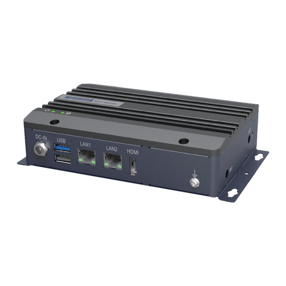
- Page 12 Introduction The following sections show the external connectors and pin assignments. EPC-R3720 I/O Overview Front I/O: Rear I/O: EPC-R3720 User Manual...
- Page 13 Left Side: Right Side: EPC-R3720 User Manual...
-
Page 14: Usb Ports
Pin Name +12V 2.3.2 USB Ports EPC-R3720 supports 1 x USB3.2 Gen 1 by 1 Type A port and 1 x USB 2.0 Type A port on the front side, which are Host. USB5 & USB6: Pin Name Pin Name... -
Page 15: Lan Ports
2.3.3 LAN Ports EPC-R3720 supports 2 x 10/100/1000Mbps LAN ports on the front side. LAN1: Pin Name Pin Name LAN1_MDI0+ LAN1_MDI0- LAN1_MDI1+ LAN1_MDI1- LAN1_MDI2+ LAN1_MDI2- LAN1_MDI3+ LAN1_MDI3- LAN1_ACT# +2.5V_VDDH1 LAN1_LED_1000# LAN1_LED_10_100# LAN2: Pin Name Pin Name LAN0_MDI0+ LAN0_MDI0- LAN0_MDI1+ LAN0_MDI1-... - Page 16 HDMI_DDC_SDA HDMI_HPD/ eARC- 2.3.5 COM / CAN EPC-R3720 supports 1 x DB9 port at the front side which is default used as debug console, but can be configured as RS-232/RS-422/RS-485, and also with 1 x CAN-FD signal. EPC-R3720 User Manual...
-
Page 17: Debug Port Connection
2.4.1 Debug Port Connection EPC-R3720 Debug port is on the front side at COM / CAN, please connect RS-232 female to female cable 1700019474 to your USB-to-RS232 Cable to your PC terminal. Note: Debug cable needs to be purchased separately. - Page 18 Figure 2.2 Power LED Indicator EPC-R3720 User Manual...
-
Page 19: Software Functionality
Chapter Software Functionality This chapter details software functions on RSB-3720. - Page 20 Display 3.1.1 HDMI When the HDMI Cable is connected, the default Weston UI(1920x1080) will be dis- played on the screen. 3.1.1.1 Test Different Resolutions: Step 1: Disable Weston UI # killall -9 weston UI Step 2: Get “connect ID” and “support resolutions # modetest -c encoder status name...
- Page 21 Step 5: Weston UI will be displayed on the screen. LVDS1- Panel: G070VW01V0 (VDD: 3.3V, Backlight Power: 12V) Step 1: Connect 96LEDK-A070WV40NB1 LVDS panel with LVDS cable (1700021883-01) to LVDS and Backlight cable (1700032155-01) to BL2. Step 2: Change VDD1 jumper to (1-2 short), BLP2 jumper to (2-3 short). Step 3: Power on.
- Page 22 Dual Channel LVDS Panel: G215HVN0 (VDD: 5V, Backlight Power: 12V) Step 1: Connect 96LEDK-A215FH30NF2 LVDS panel with LVDS cable to LVDS and Backlight cable to BL1. Step 2: Change VDD1 jumper to (2-3 short), BLP1 jumper to (2-3 short). Step 3: Connect another 12V adapter to the DC-Jack on Backlight cable. Step 4: Power on RSB-3720 and the extra 12V adapter.
- Page 23 Audio Step 1: Check audio codec # cat /proc/asound/cards 0 [sgtl5000 ]: sgtl5000 - sgtl5000 sgtl5000 1 [audiohdmi ]: audio-hdmi - audio-hdmi audio-hdmi Step 2: Audio codec (sgtl5000): 1. Set MIC and headphone: # amixer set Mic 32% Simple mixer control 'Mic',0 Capabilities: volume volume-joined Playback channels: Mono Capture channels: Mono...
- Page 24 Mini-PCIE Test 3G/4G with EWM-C117FL06E Module Step 1: Connect the PCIE card to Mini PCIE slot. Step 2: Execute the pppd command to connect the network. # ppd connect 'chat -v -s -t 10 "" "AT" "" "ATDT*99***4#" "CONNECT" ""' user username password password /dev/ttyACM2 460800 nodetach crtscts debug usepeerdns defaultroute &...
- Page 25 3.4.1 Test Wifi with EWM-W163M201E Module (PCIe Interface) # killall wpa_supplicant # ifconfig wlan0 up # wpa_passphrase “SSID” “PASSWORD” > /tmp/wpa.conf # wpa_supplicant -BDwext -iwlan0 -c/tmp/wpa.conf # udhcpc -b -i wlan0 Ping network ping 8.8.8.8 PING 8.8.8.8 (8.8.8.8) 56(84) bytes of data. 64 bytes from 8.8.8.8: icmp_seq=1 ttl=54 time=2.10 ms 64 bytes from 8.8.8.8: icmp_seq=2 ttl=54 time=2.10 ms 3.4.2...
-
Page 26: Serial Port
Serial Port For COM1 serial port pin definition, please refer to previous chapter 2.4.2.4 for more information. 3.5.1 RS-232 Loopback Test (eg. ttymxc1) # stty -F /dev/ttymxc1 -echo -onlcr 115200 # cat /dev/ttymxc1 & # echo "Serial Port Test" > /dev/ttymxc1 3.5.2 RS-422 Test Step 1: First change the debug console port to UART2 (UIO-4032 COM_3), or use... - Page 27 3.5.3 RS-485 Test Step 1: Set GPIO#496, GPIO#497 Set to 0,1 Step 2: Test RS-485 with Adam-4520. Connect Adam-4520 with COM1 with 1700100250 DB9 as the following: Adam-4520 Pin 1: Data- connect to DB9 Pin 1: COM_DCD. Adam-4520 Pin 2: Data+ connect to DB9 Pin 3: COM_RXD..
- Page 28 Step 2: Test (eg. if usb disk is /dev/sda) # dd if=/dev/urandom of=data bs=1 count=1024 # dd if=/dev/sda of=backup bs=1 count=1024 skip=4096 # dd if=data of=/dev/sda bs=1 seek=4096 # dd if=/dev/sda of=data1 bs=1 count=1024 skip=4096 # diff data data1 # dd if=backup of=/dev/sda bs=1 seek=4096 Step 1: Disable rtc sync service root@imx8mprsb3720a1:~# systemctl disable ntpd.service Removed /etc/systemd/system/multi-user.target.wants/ntpd.service.
- Page 29 3.10 Ethernet Step 1: Check Ethernet device Step 2: Connect cable and ping test (eg. Eth0) RSB-3720 User Manual...
- Page 30 3.11 GPIO 3.11.1 GPIO Pins Table 3.1: UIO Extension 1 (UIO1) Numbers GPIO2 GPIO4 Table 3.2: UIO Extension 2 (UIO2) Numbers GPIO5 GPIO6 GPIO7 GPIO8 GPIO9 GPIO10 GPIO11 GPIO12 3.11.2 GPIO Loopback Test (Using GPIO2 and GPIO4 as examples) Step 1: Connect GPIO2 and GPIO4 Step 2: Export GPIO interface root@imx8mprsb3720a1:~# echo 501 >...
- Page 31 3.12 Watchdog 3.12.1 System will reboot after 1 sec root@imx8mprsb3720a1:~# /unit_tests/Watchdog/wdt_driver_test.out 1 2 0 ---- Running < /unit_tests/Watchdog/wdt_driver_test.out > test ---- Starting wdt_driver (timeout: 1, sleep: 2, test: ioctl) Trying to set timeout value=1 seconds The actual timeout was set to 10 seconds Now reading back -- The timeout is 10 seconds U-Boot SPL 2020.04-3720A1AIM30LIVA0070+g121029b89f (Dec 01 2020 - 08:46:32 +0000)
- Page 32 3.13.3 MIPI-CSI0 (Tested with Basler daA3840-30mc Camera) Step 1: Connect the Basler camera to the mini-SAS to MIPI-CSI Cable, connect the mini-SAS cable to the ROM-EG55 board, and then connect the other side to Basler daA3840-30mc Camera Step 2: Connect the ROM-EG56 (DSI to HDMI Converter board). Step 3: Press enter after boot, system will stop at u-boot as below: Normal Boot Hit any key to stop autoboot: 0...
- Page 33 3.14 CANBus or CAN-FD (Please note that the CAN function on RSB-3720 COM1 Pin Header is CANBus only with RSB-3720CQ & RSB-3720CD, RSB-3720 COM1 Pin Header is CANB-FD only with RSB-3720WQ & RSB-3720WD) Step 1: Connect the UIO-4034 A101-2 CANbus port Pin 2 and Pin 7 to RSB-3720 COM1 with 1700100250 cable, pin 9 and Pin 6 of the DB9.
- Page 34 3.16 3.16.1 LED ON/OFF test # echo 255 > /sys/class/leds/user/brightness # echo 0 > /sys/class/leds/user/brightness 3.17 EEPROM # echo -n $'\x06\x05\x04\x03\x02\x01' > test # dd if=test of=/sys/bus/i2c/devices/3-0050/eeprom # hexdump -C /sys/bus/i2c/devices/3-0050/eeprom -n 64 3.18 UIO Extension Boards 3.18.1 UIO-4030 UART 2-wire RS-232 (UIO Extension_UIO2: COM2) UIO-4030 COM_3 /dev/ttymxc1...
- Page 35 3.18.2 UIO-4032 UART 2-wire RS-232 (UIO Extension_UIO2: COM2) UIO-4032 COM_3 /dev/ttymxc1 2-wire RS-232 (UIO Extension_UIO2: COM4) UIO-4032 COM_4 /dev/ttymxc3 # stty -F /dev/ttymxc3 -echo -onlcr 115200 # cat /dev/ttymxc3 & # echo "Serial Port Test" > /dev/ttymxc3 Can also be used as M7_Debug Port: M7_Debug: (1) emmc boot: U-Boot >...
- Page 36 For more examples and how to run PyeIQ demos on RSB-3720, please refer to the below page: http://ess-wiki.advantech.com.tw/view/AIMLinux/AddOn/Edge_AI 3.19.1 Run Applications and Demos 3.19.1.1...
- Page 37 3.19.1.2 Demos Demo Name Framework i.MX Board BSP Release Inference Core Status Object Classifica- TFLite:2.1.0 RSB-3720 5.4.24_2.1.0 GPU, NPU PASS tion Object Detection TFLite:2.1.0 RSB-3720 5.4.24_2.1.0 GPU, NPU PASS Object Detection TFLite:2.1.0 RSB-3720 5.4.24_2.1.0 GPU, NPU PASS YOLOv3 Object Detection OpenCV:4.2.0 RSB-3720 5.4.24_2.1.0 PASS...
- Page 38 Chapter Embedded O.S This chapter introduces how to build Linux systems...
- Page 39 The purpose of this chapter is to introduce software configuration and development of RSB-3720 to you, so that you can develop your own application(s) efficiently. For detailed operation, please refer to Yocto Linux BSP Ver.A User Guide for iMX8 series form Wiki page: http://ess-wiki.advantech.com.tw/view/IoTGateway/BSP/ Linux/iMX8/Yocto_LBVA_User_Guide 4.1.1 Device Tree Source File Select for RSB-3720 4.1.1.1...
-
Page 40: System Recovery
Chapter System Recovery This chapter details system recov- ery for damaged Linux OS. - Page 41 System Recovery This section provides detail procedures of restoring the eMMC image. If you destroy the onboard flash image by accident, you can recover a system following steps. 5.1.1 Recovery by SD Card Copy 3720A1AIM30LIVA0070_iMX8MP_flash_tool.tgz package to your desk- top. Insert SD card to PC.
-
Page 42: Advantech Services
Chapter Advantech Services This chapter outlines Advantech’s Design-In services, technical sup- port, and warranty policy for RSB- 3720. -
Page 43: Risc Design-In Services
Comprehensive document support Design Assistance Service Advantech provides a checklist for engineers to easily check their schematics as well as several services for reviewing customer carrier board schematics. These services aim to help identify design errors before implementation, which saves substantial development time and costs. - Page 44 Advantech has been involved in the industrial computer industry for many years and found that customers usually have the following questions when implementing modu- lar designs.
- Page 45 RISC COM. Design Stage When a product moves into the design stage, Advantech will supply a carrier board design guide for reference. The carrier board design guide provides pin definitions of the COM connector with limitations and recommendations for carrier board design.
-
Page 46: Contact Information
In addition to verifying the product’s functionality, the product’s efficiency must also be tested at this stage, particularly with RISC platforms. Advantech plays a supportive role in helping customers solve problems during the testing and verification process and will provide suggestions and tips as well. -
Page 47: Global Service Policy
The DOA cross-shipment excludes any shipping damage, customized and/or build- to-order products. For products that are not DOA, the return fee to an authorized Advantech repair facil- ity will be at the customer’s expense. The shipping fee for reconstructed products from Advantech back to the customer will be at Advantech’s expense. - Page 48 “Attn. RMA Service Department”. All products must be returned in properly packed ESD material or anti-static bags. Advantech reserves the right to return unrepaired items at the customer's cost if inap- propriately packed. Door-to-Door transportation, such as speed post, is recommended for delivery. Oth- erwise, the sender should bear additional charges such as clearance fees if air cargo shipment methods are used.
- Page 49 tomer who is without warranty. If a product has been repaired by Advantech, and within three months after such a repair the product requires another repair for the same problem, Advantech will con- duct the repair free of charge. However, free repairs do not apply to products that have been misused, abused, or subjected to unauthorized disassembly/modification;...
- Page 50 RSB-3720 User Manual...
- Page 51 No part of this publication may be reproduced in any form or by any means, such as electronically, by photocopying, recording, or otherwise, without prior written permission from the publisher. All brand and product names are trademarks or registered trademarks of their respective companies. © Advantech Co., Ltd. 2021...
Need help?
Do you have a question about the EPC-R3720 and is the answer not in the manual?
Questions and answers