
Related Manuals for Advantech ECU-4784 Series


Summary of Contents for Advantech ECU-4784 Series
- Page 1 User Manual ECU-4784 Series Intel® Haswell Core i7 Power & Energy Automation Computer with 8 x LAN, 10 x COM and 2 x Expansion Slots...
- Page 2 No part of this manual may be reproduced, copied, translated or transmitted in any form or by any means without the prior written permission of Advantech Co., Ltd. Information provided in this manual is intended to be accurate and reliable. How- ever, Advantech Co., Ltd.
- Page 3 Because of Advantech’s high quality-control standards and rigorous testing, most of our customers never need to use our repair service. If an Advantech product is defec- tive, it will be repaired or replaced at no charge during the warranty period. For out- of-warranty repairs, you will be billed according to the cost of replacement materials, service time and freight.
-
Page 4: Declaration Of Conformity
This product has passed the CE test for environmental specifications when shielded cables are used for external wiring. We recommend the use of shielded cables. This kind of cable is available from Advantech. Please contact your local supplier for ordering information. -
Page 5: Safety Instructions
The sound pressure level at the operator's position according to IEC 704-1:1982 is no more than 70 dB (A). DISCLAIMER: This set of instructions is given according to IEC 704-1. Advantech disclaims all responsibility for the accuracy of any statements contained herein. - Page 6 Safety Precaution - Static Electricity Follow these simple precautions to protect yourself from harm and the products from damage. To avoid electrical shock, always disconnect the power from your PC chassis before you work on it. Don't touch any components on the CPU card or other cards while the PC is on.
-
Page 7: Table Of Contents
Introduction ....................2 Hardware Specifications: ................3 Environment ....................4 Function Block Diagram ................5 Figure 1.1 ECU-4784 Series Product Function Block....5 Safety Precautions ..................6 Chassis Dimensions.................. 7 Figure 1.2 ECU-4784 Series Chassis Dimensions ...... 7 Figure 1.3 ECU-4784 Series Explode picture......8 Packing List.................... - Page 8 2.11 Expansion PCI & PCIE: ................22 2.12 AMT ......................22 2.13 TPM ......................22 Chapter Initial Setup........23 Configuration................... 24 Figure 3.1 ECU-4784 screw location......... 24 Figure 3.2 ECU-4784 removing top cover ......... 24 Figure 3.3 ECU-4784 open chassis top cover......25 Installing a CFast Card ................
- Page 9 C.2.1 Main Setup.................. 45 Figure C.2 Main setup screen ............ 45 C.2.2 Advanced BIOS Features Setup..........46 Figure C.3 Advanced BIOS features setup screen ....46 Figure C.4 ACPI Setting ............. 47 Figure C.5 Trusted Computing ........... 48 Figure C.6 CPU Configuration............ 49 Figure C.7 SATA Configuration..........
- Page 10 ECU-4784 User Manual...
-
Page 11: Chapter 1 Overview
Chapter Overview This chapter provides an overview of the ECU-4784 Series specifica- tions. Sections include: Introduction Hardware Specifications Safety Precautions Block Diagram Chassis Dimensions Packing List... -
Page 12: Introduction
Advantech’s ECU-4784 Series are certified by IEC 61850-3 and IEEE 1613 to meet the harsh and critical requirements of smart grid automation ; It provide high perfor- mance and reliable functionality to meet the most critical computing applications for Virtualization solutions to reduce project deployment and maintenance costs ;... -
Page 13: Hardware Specifications
Easy to Diagnose System & Communication and Enhance Maintenance Effi- ciency Remote Monitor & Diagnose and Manage System to provide the high system maintenance efficiency by AMT(built in Remote KVM) to quick access to remote device’s desktop for diagnosis and troubleshooting without on-site technical support to reduce maintenance costs. -
Page 14: Environment
I/O Interface Serial Ports: – 2 x DB-9 RS-232 (5-Pin) – 8 x screw terminals with 3-wired RS-422/485 (Terminal Block) (Automatic RS-485 data flow control) 2,000 VDC isolation Serial Port Speed: – (COM1, COM2) RS-232: 50 ~ 115200 bps, –... -
Page 15: Function Block Diagram
PCIE958 STM32F373 LAN&COM States COM3 COM4 COM7 COM8 PCIe Monitoring PI7C9X20404 COM5 COM6 COM9 COM10 PCIe SWITCH PCIe PCIe PCIe PEX8112 PCIe to PCI Slot 1 Slot 2 Extension Board Figure 1.1 ECU-4784 Series Product Function Block ECU-4784 User Manual... -
Page 16: Safety Precautions
Caution! Always ground yourself to remove any static electric charge before touching ECU-4784 Series Modern electronic devices are very sensitive to static electric charges. Use a grounding wrist strap at all times. Place all electronic components on a static-dissipative surface or in a static- shielded bag. -
Page 17: Chassis Dimensions
Chassis Dimensions Figure 1.2 ECU-4784 Series Chassis Dimensions ECU-4784 User Manual... -
Page 18: Packing List
Figure 1.3 ECU-4784 Series Explode picture Packing List The accessory package of ECU-4784 Series contains the following items: ECU-4784 Accessory: (A) 1 x ECU-4784 Product (B) 4 x 10-pins green screw terminals (C) 16 x jumper shorters (D) 2 x M3 black screws for USB clamp... -
Page 19: Chapter 2 Hardware Function
Chapter Hardware Function This chapter shows how to setup the hardware functions, including connecting peripherals, setting jumpers and indicators. Sections include: Overview LED Indicators Power Input RS-232 Interface RS-422/485 Interface Relay Out LAN: Ethernet Connector ... -
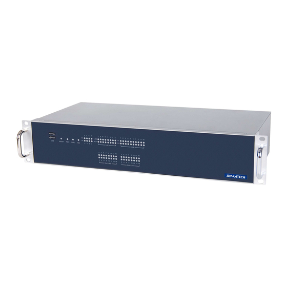
Page 20: Overview
Overview The following figures show the indicators and connectors on the ECU-4784 Series. The following sections give you detailed information about function of each periph- eral. 2.1.1 ECU-4784 LED and Interface position Figure 2.1 ECU-4784 Front Panel Figure 2.2 ECU-4784 Rear Panel <Single Power Supply >... -
Page 21: Led Indicators
LED Indicators 2.2.1 ECU-4784 LED Indicators The LEDs in the front panel can be divided into 3 groups. 2.2.1.1 System Status Indicators Table 2.1: Definition of System Status Indicators Item LED Status Description Green System power1 is on PWR1 System power1 is off Green System power2 is on PWR2... -
Page 22: Table 2.2: Definition Of Lan Status Indicators
2.2.1.4 Programmable LED The ECU-4784 Series products provide 8 programmable indicating LEDs, which are convenient for users to control the Programmable LED state (green, off) using API programming, it can be used to indicate and edit this machines operating status, a detailed explanation of the API programming. -
Page 23: Power Input
. You can find the example in the below installation path, it is located in the "C:\Program Files\Advantech\AdvPLED\Examples\VC++\PLEDTool" directory. Power Input The ECU-4784 Series products support single power input AC or DC, It is reserved for dual power supply input interface, to facilitate customer to extend using dual power specifications. -
Page 24: Table 2.6: Ac/Dc Power Input Pin Definition
47-63 Hz PWR2 100-240 V 0.5 A (max) ~ 0.3 A (min) 3Pin Screw Terminal The ECU-4784 Series supports ATX /AT Power Mode, user can set Power Mode Selection by Jumper setting of CN60 to enable ATX/AT mode. ECU-4784 User Manual... -
Page 25: Table 2.8: Jumper Setting Of Atx/At Power Mode Selection
Figure 2.6 AT X /AT Power Mode Select location (CN60) RS-232 Interface (COM1,COM2) The ECU-4784 Series offers two standard RS-232 serial communication interface ports: COM1 and COM2. Please refer to A.1 for pin assignments. It can not support the IRQ, I/O address is the same with Supper I/O. -
Page 26: Rs-232 Interface (Com1,Com2)
RS-232/422/485 Interface (COM3~COM10) The ECU-4784 Series offers 8 ports RS-232/422/485 serial communication interface ports: COM3 to COM10. Please refer to Appendix A.2 for their pin assignments. Users can select each port for RS-232 or RS-422/485 through different connections. Table 2.9: Jumper setting of RS-232/RS-422/RS-485 Selection (For... -
Page 27: Cn23)
CN23/22/20/18/16/21/19/17 Figure 2.7 COM3~10 Port Related Jumper Locations (CN16-CN23) Figure 2.8 COM3~10 Port Related Jumper Locations(SW2) ECU-4784 User Manual... -
Page 28: Oxpcie958 Uarts With 128 Bytes Fifo
2.5.3 Automatic Data Flow Control Function for RS-485 In RS-485 mode, the ECU-4784 Series automatically detects the direction of incom- ing data. So no handshake signal (e.g. RTS signal) is necessary. This lets you conve- niently build an RS-485 network with just two wires. -
Page 29: Table 2.13: Mapping Table Of Jumper For Com (3~10) Port
Table 2.13: Mapping Table of Jumper for COM (3~10) Port COM Port Jumper for Terminal Resistor COM3 CN27 COM4 CN28 COM5 CN29 COM6 CN30 COM7 CN31 COM8 CN32 COM9 CN33 COM10 CN34 CN34/33/31/29/27/32/30/28 Figure 2.9 COM3~10 Port Related Jumper Locations(CN27-CN34) ECU-4784 User Manual... -
Page 30: Relay Output For Event
Figure 2.10 Relay output connections Figure 2.11 Wiring Diagram of the Relay Out The ECU-4784 Series products provide Relay out Alarm Function, which is conve- nient for the user to control the Relay out Alarm by the API, for the detailed explana- tion of the Relay out API, please refer to C:\Program Files\Advantech\AdvRelay\Examples\VC++\RelayTool"... -
Page 31: Lan: Ethernet Connector
The USB interface complies with USB UHCI, Rev. 2.0 compliant. The USB interface can be disabled in the system BIOS setup. ECU-4784 SERIES provides 1 USB port on the front panel, and 3 USB port on the rear panel. It also provides 1 USB port inside the chassis for USB dongle key. -
Page 32: Expansion Pci & Pcie
The ECU-4784 Series offers 2 expansion slots for modularized domain I/O plug-in cards. Through the interface card, the ECU-4784 Series can also use standard PCI cards, PCIe cards, mini-PCI cards as well as the PCI-104 card. Due to the ECU-4784 Series being an embedded system, the power providing for the expansion slot is lim- ited. -
Page 33: Initial Setup
Chapter Initial Setup Sections include: Configuration Installing a CompactFlash Card Installing a USB Dongle Installing Hard Disk Installation on Rack BIOS Setup and System Assign- ments... -
Page 34: Configuration
Configuration To open the ECU-4784 Series product chassis, follow the steps below: Remove all power and signal connections. Remove the screws shown below. Figure 3.1 ECU-4784 screw location Remove the chassis’s top cover: Figure 3.2 ECU-4784 removing top cover ECU-4784 User Manual... -
Page 35: Installing A Cfast Card
Figure 3.3 ECU-4784 open chassis top cover Installing a CFast Card The ECU-4784 Series provides 1 CFast Card slot, to install the cards: Unscrew the 2 screws and remove the CFast back plate Figure 3.4 CFast Card Slot Location (CN3) -
Page 36: Figure 3.5 Cfast Card Slot Location (Cn45)
Insert the card at location (CN45) shown below. CN45 Figure 3.5 CFast Card Slot Location (CN45) ECU-4784 User Manual... -
Page 37: Installing A Usb Dongle
Installing a USB Dongle The ECU-4784 Series provides a clamp for the USB dongle which can be installed inside the chassis. Follow the steps to install the USB dongle and clamp: Refer to section 3.1 to open the chassis. Figure 3.6 Open the chassis Plug the USB Dongle in the upper port of CN14, note that the lower port is a dummy port. -
Page 38: Figure 3.8 Cn37 Location Of Internal Usb Port
CN37 Figure 3.8 CN37 Location of Internal USB Port Adjust the position of the kit to fasten the USB dongle, and then screw to fix the kit. ECU-4784 User Manual... -
Page 39: Installing A Hard Disk
Installing a Hard Disk Follow the steps below to install a HDD: To install a HDD and HDD bracket (in the accessory). Figure 3.9 SATA HDD Fixed diagram ECU-4784 User Manual... -
Page 40: (Cn42/44, Cn42/43)
According to the schematic drawing, HDD is directly installed on the device through the DIN-Rails (ECU-4784 Series product supports up to 2 x HDD). ECU-4784 series contains SATA signal and power cable for two SATA HDD in the chassis. The locations of the connectors are shown below, SATA signal con- nector locates on CN42/44 and SATA power connector locates on CN41/43. -
Page 41: Rack Installation
2Us available. Advantech will not provide the cabinet for customers. The ECU-4784 Series has Aluminum Fins on the top of the unit as heat-sink. It can generate nature convection for better heat transmission. To have optimal thermal performance, leave 2U (440 mm) space above the unit. -
Page 42: Bios Setup And System Assignments
Then secure the expansion cards using the previously removed screws. BIOS Setup and System Assignments The ECU-4784 Series adopts Advantech's SOM-6894 CPU module. Further informa- tion about the SOM module, can be found in SOM's user's manual. You can find this manual on the ECU-4784 SERIES's companion disc. -
Page 43: Appendix A Pin Assignments
Appendix Pin Assignments... -
Page 44: Rs-232 Serial Ports (Com1 ~ Com2)
RS-232 Serial Ports (COM1 ~ COM2) Table A.1: COM (1~2 ) Port Pin Definitions Pins RS-232 RS-232/422/485 Serial Ports (COM3 ~ COM10) Table A.2: RS-232/422/485 Serial Ports (COM3 ~ 10) Pins RS-232 RS-422 RS-485 Data+ Data- ECU-4784 User Manual... -
Page 45: Relay Output Connectors Pin Assignments
Table A.3: Relay Output Connectors Pin Definitions Pins Definitions Normal OPEN COMMON Reference Normal CLOSE Power Failure and Relay out Function Power 1 Status Power 2 Status Relay Out function NC(Normally Close) Software control Software control Software control Relay Output Connectors Pin Assignments USB Connectors (USB1 ~ USB5) Table A.4: USB Connector Pin Assignments Signal... -
Page 46: Lan Connectors (Lan1~Lan8)
LAN Connectors (LAN1~LAN8) Table A.5: LAN Connector Pin Assignments Assignment Description Transmit + Transmit - RD + Receive + not used not used RD - Receive - not used not used VGA Display Connector Table A.6: VGA Adaptor Cable Pin Assignments Signal GREEN BLUE... -
Page 47: Dvi Display Connector
DVI Display Connector Table A.7: DVI Adaptor Cable Pin Assignments Signal TMDS_C2# TMDS_C2 CRT_DDC_CLK CRT_DDC_DATA MDVI_CLK MDVI_DATA VGAVSY TMDS_C1# TMDS_C1 VCC_DVI VGA Detect HP_DET TMDS_C0# TMDS_C0 TMDS_CK# TMDS_CK VGAR VGAG VGAB VGAHSY ECU-4784 User Manual... -
Page 48: Power Pin Assignments
POWER Pin Assignments Table A.8: AC/DC Power Input PIN Definition Pins Screen printing Function Description L/V+ PWR1 AC/DC power input PIN N/V- PWR1 AC/DC power input PIN Note! If the customer wants to use a dual power supply, refer to Table2.10 for power input specifications. -
Page 49: Appendix B Watchdog Timer Programming
Appendix Watchdog Timer Programming... -
Page 50: Watchdog Timer Programming
Watchdog Timer Programming -------------------------------------------------------------- --------------------- Enter the extended function mode, interruptible double-write -------------------------------------------------------------- --------------------- MOV DX,2EH MOV AL,87H OUT DX,AL OUT DX,AL -------------------------------------------------------------- --------------- Configured logical device 8, configuration register CRF6 -------------------------------------------------------------- --------------- MOV DX,2EH MOV AL,2BH OUT DX,AL MOV DX,2FH IN AL,DX AND AL.OEFH;... - Page 51 OUT DX,AL ;------------------------------------------ ; Exit extended function mode ;------------------------------------------ MOV DX,2EH MOV AL,AAH OUT DX,AL ECU-4784 User Manual...
- Page 52 ECU-4784 User Manual...
-
Page 53: Appendix Cbios Setup
Appendix BIOS Setup... -
Page 54: Bios Setup And System Assignments
BIOS Setup and System Assignments The ECU-4784 Series adopts Advantech's SOM-6894 CPU module. Further informa- tion about the SOM module, can be found in SOM' user's manual. You can find this manual on the ECU-4784 Series companion Disc. Please note that you can try to "LOAD BIOS DEFAULTS" from the BIOS Setup if the ECU-4784 Series does not work properly. -
Page 55: Entering Setup
Entering Setup Turn on the computer and then press <F2> or <DEL> to enter Setup menu. C.2.1 Main Setup When users first enter the BIOS Setup Utility, users will enter the Main setup screen. Users can always return to the Main setup screen by selecting the Main tab. There are two Main Setup options. -
Page 56: C.2.2 Advanced Bios Features Setup
C.2.2 Advanced BIOS Features Setup Select the Advanced tab from the ECU-4784 setup screen to enter the Advanced BIOS Setup screen. Users can select any item in the left frame of the screen, such as CPU Configuration, to go to the sub menu for that item. Users can display an Advanced BIOS Setup option by highlighting it using the <Arrow>... -
Page 57: Figure C.4 Acpi Setting
C.2.2.1 ACPI Settings Figure C.4 ACPI Setting Enable ACPI Auto Configuration This item allows users to enable or disable BIOS ACPI auto configuration. Enable Hibernation This item allows users to enable or disable hibernation. ACPI Sleep State This item allows users to set the ACPI sleep state. -
Page 58: Figure C.5 Trusted Computing
C.2.2.2 Trusted Computing Figure C.5 Trusted Computing Security Device Support This item allows users to enable or disable BIOS support for security device support, and the OS will not show the Security Device. TCG EFI Protocol and INT1A interface will not be available. ECU-4784 User Manual... -
Page 59: Figure C.6 Cpu Configuration
C.2.2.3 CPU Configuration Figure C.6 CPU Configuration Hyper-threading Enable for Windows XP and Linux (OS optimized for Hyper-Threading Technol- ogy) and Disable for other OS (OS not optimized for Hyper-Threading Technol- ogy) and Disable for other OS (OS not optimized for Hyper-Threading Technol- ogy). -
Page 60: Figure C.7 Sata Configuration
CPU AES This item allows users to enable or disable CPU Advanced Encryption Standard instructions. Boot performance mode This Item allows users to select the performance state that the BIOS will set before OS handoff. EIST This item allows users to enable or disable Intel SpeedStep. ... - Page 61 SATA Controller(s) This item allows users to enable or disable SATA devices. SATA Mode Selection This item allows users to select SATA mode selection. (Determines how SATA controller(s) operate) Aggressive LPM Support This item allows users to enable or disable PCH to aggressively enter link power state.
-
Page 62: Figure C.8 Pch-Fw Configuration
C.2.2.5 PCH-FW Configuration Figure C.8 PCH-FW Configuration MDES BIOS Status Code This item allows users to enable or disable MDES BIOS status code. TPM Device Selection This item allows users to enable or disable TPM Device Selection. (PTT or dTPM. -
Page 63: Figure C.9 Firmware Update Configuration
Firmware Update Configuration Figure C.9 Firmware Update Configuration – ME FW Image Re-Flash This item allows users to enable or disable ME FW Image Re-Flash function. C.2.2.6 AMT Configuration Figure C.10 AMT Configuration ECU-4784 User Manual... - Page 64 Intel AMT This item allows users to enable or disable Intel AMT (Active Management Technology) BIOS Extension. Note! iAMT H/W is always enabled. This option just controls the BIOS exten- sion execution. If enabled, this requires additional firmware in the SPI device.
-
Page 65: Figure C.11Usb Configuration
C.2.2.7 USB Configuration Figure C.11 USB Configuration Legacy USB Support Enable the support for legacy USB. Auto option disables legacy support if no USB devices are connected. Auto option disables legacy support if no USB devices are connected. Disable option will keep USB devices available only for EFI applications. -
Page 66: Figure C.12Super I/O Configuration
Device power-up delay This item allows users to select device power-up section. Maximum time the device will take before it properly reports itself to the Host controller. "Auto" uses a default value: for a Root port it is 100ms, for a Hub port the delay is taken from the Hub descriptor. -
Page 67: Figure C.13Com Port 1 Configuration
Figure C.13 COM Port 1 Configuration – COM Port 1 This item allows users to enable or disable the COM Port. – Change settings This item allows users to select an optimal setting for Super I/O device. COM Port 2 Configuration Figure C.14 COM Port 2 Configuration ECU-4784 User Manual... -
Page 68: Figure C.15 Parallel Port Configuration
– COM Port 2 This item allows users to enable or disable the COM Port. – Change settings This item allows users to select an optimal setting for the Super IO device. – Device Mode This item allows users to change the Serial Port mode. Select <High Speed> or <Normal Mode>... -
Page 69: Figure C.16Pc Hardware Monitor
Hardware Monitor This item monitors hardware status. Figure C.16 PC Hardware Monitor C.2.2.9 iManager Configuration Figure C.17 iManager Configuration ECU-4784 User Manual... -
Page 70: Figure C.18Com 3 Configuration
CPU Shutdown Temperature This item allows users to select CPU Shutdown Temperature. iManager Smart Fan - COM Module This item allows users to enable or disable iManager Smart Fan - COM Module. To control iManager Smart FAN function. ... -
Page 71: Figure C.19Com Port 4 Configuration
COM Port 4 Configuration Figure C.19 COM Port 4 Configuration – COM Port 4 This item allows users to enable or disable a COM Port. – Change settings This item allows users to select an optimal setting for the Super IO device. –... -
Page 72: Figure C.20Hardware Monitor
Hardware Monitor This item monitor hardware status. Figure C.20 Hardware Monitor C.2.2.10Serial Port Console Redirection Figure C.21 Serial Port Console Redirection ECU-4784 User Manual... -
Page 73: C.2.3 Chipset
COM1 Console Redirection This item allows users to enable or disable Console Redirection. COM2 Console Redirection This item allows users to enable or disable Console Redirection. COM3 Console Redirection This item allows users to enable or disable Console Redirection. COM4 Console Redirection ... -
Page 74: Figure C.23Pch-Io Configuration
C.2.3.1 PCH-IO Configuration Figure C.23 PCH-IO Configuration PCI Express Configuration This item allows users to change PCI Express Configuration settings. USB Configuration This item allows users to change USB Configuration settings. PCH Azalia Configuration This item allows users to change PCH Azalia Configuration settings. ... -
Page 75: Figure C.24Pci Express Configuration
PCI Express Configuration Figure C.24 PCI Express Configuration – PCI Express Clock Gating This item allows users to enable or disable PCI Express Clock Gating for each root port. – DMI Link ASPM Control This item allows users to enable or disable DMI Link ASPM Control. The Control of Active State Power Management on both NB side and SB side of the DMI Link. -
Page 76: Figure C.25Pci Express Root Port 1 Configuration
– PCI Express Root Port 1 Configuration Figure C.25 PCI Express Root Port 1 Configuration PCI Express Root Port 1 This item allows users to enable or disable PCI Express Root Port. ASPM Support This item allows users to set the ASPM level. Force L0s- Force all links to L0s state. -
Page 77: Figure C.26Pci Express Root Port 2 Configuration
This item allows users to select Reserved I/O (4k/8k/12k/16k…/48k) range for this root bridge. PCIE LTR This item allows users to enable or disable PCIE LTR. PCIE LTR Lock This item allows users to enable or disable PCIE LTR Configuration Lock. Snoop Latency Ocerride This item allows users to select Snoop Latency Ocerride for PCH PCIE. -
Page 78: Figure C.27Pci Express Root Port 3 Configuration
PCIe Speed This item allows users to select PCIe Speed. Detect Non-Compliance Device This item allows users to enable or disable Detect Non-Compliance Device. If enable, it will take more time at POST time. Extra Bus Reserved This item allows users to select Extra Bus Reserved (0~7) for bridges behind this root bridge. - Page 79 PCI Express Root Port 3 This item allows users to enable or disable PCI Express Root Port. ASPM Support This item allows users to set the ASPM level. Force L0s- Force all links to L0s state. Auto-BIOS auto configure Disable- disables ASPM L1 Substates This item allows users to change L1 Substates settings.
-
Page 80: Figure C.28Pci Express Root Port 4 Configuration
– PCI Express Root Port 4 Configuration Figure C.28 PCI Express Root Port 4 Configuration PCI Express Root Port 4 This item allows users to enable or disable PCI Express Root Port. ASPM Support This item allows users to change L1 Substates settings. PME SCI This item allows users to enable or disable PME SCI. -
Page 81: Figure C.29Usb Configuration
PCIE LTR This item allows users to enable or disable PCIE LTR. PCIE LTR Lock This item allows users to enable or disable PCIE LTR Configuration Lock. Snoop Latency Ocerride This item allows users to select Snoop Latency Ocerride for PCH PCIE. Non Snoop Latency Ocerride This item allows users to select Non Snoop Latency Ocerride for PCH PCIE. -
Page 82: Figure C.30Pch Azalia Configuration
PCH Azalia Configuration Figure C.30 PCH Azalia Configuration – Azalia This item allows users to change Azalia settings. Control detection of the Azalia device. Disable- Azalia will be unconditionally Disabled Enabled- Azalia will be unconditionally Enabled Auto- Azalia will be enabled if present, disabled otherwise. ECU-4784 User Manual... -
Page 83: Figure C.31System Agent (Sa) Configuration
C.2.3.2 System Agent (SA) Configuration Figure C.31 System Agent (SA) Configuration CHAP Device (B0:D7:F0) This item allows users to enable or disable SA CHAP Device. Thermal Device (B0:D4:F0) This item allows users to enable or disable SA Thermal Device. ... -
Page 84: Figure C.32Graphics Configuration
Graphics Configuration Figure C.32 Graphics Configuration – Graphics Turbo IMON Current Shows graphics turbo IMON Current values supported (14-31) – Primary Display This item allows users to select which of IGFX/PEG/PCI Graphics device should be Primary display or select SG for Switchable Gfx. –... -
Page 85: Figure C.33Lcd Control
– LCD Control This item allows users to perform LCD control. Figure C.33 LCD Control Primary IGFX Boot Display This item allows users to select the Video Device which will be activated dur- ing post. This has no effect if external graphics present. VGA: DDI2 (EFP2) DP to VGA by Chrontel CH7517A-BF DDI1: DDI1 (EFP) for HDMI (Default)/DP/DVI LVDS: eDP to LVDS(LFP) by Chrontel CH7511B-BF... -
Page 86: Figure C.34Memory Configuration
Memory Configuration Figure C.34 Memory Configuration – Memory Information This item shows memory configuration parameters. GT- Power Management Control Figure C.35 GT- Power Management Control – RC6 (Render Standby) This item allows users to enable or disable RC6 (Render Standby) support. ECU-4784 User Manual... -
Page 87: C.2.4 Boot
C.2.4 Boot Figure C.36 Boot Setup Utility Setup Prompt Timeout This item allows users to select the number of seconds to wait for setup activa- tion key. Bootup NumLock State Select the keyboard NumLock state. Quiet Boot This item allows users to enable or disable Quiet Boot option. -
Page 88: Figure C.37Csm Parameters
C.2.4.1 CSM parameters Figure C.37 CSM parameters Launch CSM This item allows users to enable or disable Launch CSM. Boot option filter This item allows users to select Boot option filter setting. Launch PXE OpROM policy This item allows users to select Launch PXE OpROM policy setting. ... -
Page 89: C.2.5 Security Setup
C.2.5 Security Setup Figure C.38 Security Setup Select Security Setup from the SOM-6894 Setup main BIOS setup menu. All Security Setup options, such as password selection is described in this section. To access the sub menu for the following items, select the item and press <Enter>: ... -
Page 90: C.2.6 Save & Exit
C.2.6 Save & Exit Figure C.39 Save & Exit Save Changes and Exit When users have completed system configuration, select this option to save changes, exit BIOS setup menu and reboot the computer if necessary to take effect all system configuration parameters. ... - Page 91 Save User Defaults When users have completed system configuration, select this option to save changes as user defaults without exit BIOS setup menu. Restore User Defaults The users can select this option to restore user defaults. Boot Override This item allows users to choose boot device.
- Page 92 No part of this publication may be reproduced in any form or by any means, electronic, photocopying, recording or otherwise, without prior written permis- sion of the publisher. All brand and product names are trademarks or registered trademarks of their respective companies. © Advantech Co., Ltd. 2015...
Need help?
Do you have a question about the ECU-4784 Series and is the answer not in the manual?
Questions and answers