Table of Contents
Advertisement
Quick Links
Advertisement
Table of Contents

Subscribe to Our Youtube Channel
Related Manuals for Advantech EPC-R4710


Summary of Contents for Advantech EPC-R4710
- Page 1 User Manual EPC-R4710 Rockchip Arm® Cortex®-A72 BOX Computer...
- Page 2 No part of this manual may be reproduced, copied, translated or transmitted in any form or by any means without the prior written permission of Advantech Co., Ltd. Information provided in this manual is intended to be accurate and reliable. How- ever, Advantech Co., Ltd.
- Page 3 The equipment has been dropped and damaged. The equipment shows obvious signs of breakage. DISCLAIMER: This set of instructions is given according to IEC 704-1. Advantech disclaims all responsibility for the accuracy of any statements contained herein. EPC-R4710 User Manual...
- Page 4 * Please contact us to find a suitable cellular module for your region. Ordering Information Part No. Description EPC-R4710 RK3399 2GDDR16Gemc system, 0 ~ 50 °C (32 ~ EPC-R4710NO-XAA1E 122 °F) EPC-R4710 RK3399 2GDDR16Gemc system, -20 ~ 70 °C (-4 EPC-R4710IO-XAA1E ~ 158 °F)
-
Page 5: Table Of Contents
Specification.................. 2 Mechanical Specifications................. 3 Electrical Specifications ................3 Environmental Specifications ..............3 Chapter Installation........5 Introduction ....................6 EPC-R4710 I/O Overview ................. 6 ECP-R4710 Outside Connectors .............. 7 2.3.1 GPIOs ................... 7 2.3.2 COM2.................... 8 2.3.3 COM 1, COM 3/4, and COM 5/6........... 9 2.3.4... - Page 6 3.9.4 Ethernet ..................31 3.10 I2C ......................32 Chapter Advantech Services......33 RISC Design-in Services ................ 34 Contact Information................. 37 Global Service Policy ................38 4.3.1 Warranty Policy................38 4.3.2 Repair Process ................39 EPC-R4710 User Manual...
-
Page 7: Chapter 1 General Introduction
Chapter General Introduction This chapter details background information on the EPC-R4710. Sections include: Introduction Specifications... -
Page 8: Introduction
4K displays via HDMI. It delivers both dual HDMI/LVDS/eDP and diverse I/ O — including GbE, 6 x serials, 6 x USB, and 5 x GPIO. EPC-R4710 also features Mini-PCIe, M.2, and SIM card slots for integrating Wi-Fi, Bluetooth, and 3G/4G mod- ules. -
Page 9: Mechanical Specifications
(32 ~ 122 °F/-4 ~ 158 °F) Operating humidity: 0 ~ 90% relative humidity, non-condensing Storage temperature: -40 ~ 85 °C (-40 ~ 185 °F) Storage humidity: 60 °C/140 °F @ 95% RH Non-condensing EPC-R4710 User Manual... - Page 10 EPC-R4710 User Manual...
-
Page 11: Chapter 2 H/W Installation
Chapter H/W Installation This chapter details mechanical and connector information for the EPC-R4710. Sections include: Connector Information Mechanical Diagrams Quick Start Guide... -
Page 12: Introduction
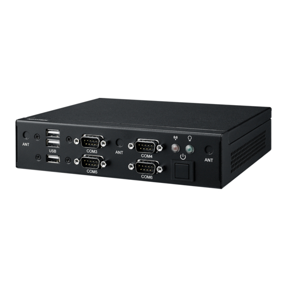
Introduction The following sections show the external connectors and pin assignments. EPC-R4710 I/O Overview Front I/O System WLAN power 2 x RS232 Antenna 3 x USB 2.0 Power on Antenna 2 x RS232/485 (Reserved) (Reserved) Rear I/O USB 2.0 Antenna... -
Page 13: Ecp-R4710 Outside Connectors
Left-Side ECP-R4710 Outside Connectors 2.3.1 GPIOs EPC-R4710 supports 5 x GPIOs via a DB9 connector. Description Description GPIO1 GPIO2 GPIO4 GPIO5 GPIO6 EPC-R4710 User Manual... -
Page 14: Com2
COM4_TXD COM2 RS232/ debug Uart2 is used for com port and debug mode selection Part number 1653003101 Footprint HD_3x1P_79_D Description PIN HEADER 3x1P 2.0 mm 180D(M) DIP 2000-13 WS Setting Function (1-2) Debug Port (Default) (2-3) RS232 EPC-R4710 User Manual... -
Page 15: Com 1, Com 3/4, And Com 5/6
COM1 can only be used as RS232 with 2 wires. Description Description COM4_RXD COM4_TXD COM 3 and COM 4 can only be used as RS232 with 4 wires. COM3: Description Description COM3_RXD COM3_TXD COM3_RTS COM3_CTS COM4: Description Description COM4_RXD COM4_TXD COM4_RTS COM4_CTS EPC-R4710 User Manual... - Page 16 RS485, they can select the impedance on/off using J1. Otherwise EPC- R4710 supports 12/5V @0.5A power supply via COM 5 and COM 6. Power levels can be selected using J3. COM5: Description Description COM5_DCD COM5_RXD COM5_TXD COM5_RTS COM5_CTS COM6: Description Description COM6_DCD COM6_RXD COM6_TXD COM6_RTS COM6_CTS EPC-R4710 User Manual...
- Page 17 COM5 and COM6 RS485 impedance ON/OFF Part number 1653003201-01 Footprint HD_3x2P_79_D_PRX Description PIN HEADER 2X3P 2.00mm 180D(M) DIP 1140-010-06SN Setting Function (1-3) COM5 RS485 impedance OFF (3-5) COM5 RS485 impedance ON (2-4) COM6 RS485 impedance OFF (4-6) COM6 RS485 impedance ON EPC-R4710 User Manual...
- Page 18 COM3/4 12/5V select COM5 and COM6 power 12 and 5V level select Part number 1653003101 Footprint HD_3x1P_79_D Description PIN HEADER 3x1P 2.0 mm (.078 in) 180D(M) DIP 2000-13 WS Setting Function (1-2) (2-3) EPC-R4710 User Manual...
-
Page 19: Dc Power Jack (Dcin1)
2.3.4 DC Power Jack (DCIN1) EPC-R4710 supports a DC-jack header that can be connected 12V DC external power input. Description V_DC_IN (12V) EPC-R4710 User Manual... -
Page 20: Power Button
2.3.5 Power Button EPC-R4710 utilizes ATX mode by default. You can configure AT mode using SW1. AT & ATX switch COM 5 and COM 6 RS485 impedance ON/OFF AT & ATX Mode Switch Part number 1600000071 Footprint SW_3P_CJS-1201TA1 Description SLIDE SW CJS-1201TA1 SMD 3P SPDT P=6.0mm W=2.5mm... -
Page 21: Quick Start Guide
Figure 2-7. After the bootloader is programmed on the SD card, insert the power adapter connector to the DC jack on EPC-R4710 to power up the board. The bootloader prompt is displayed on the terminal screen. Figure 2.1 HyperTerminal Settings for Terminal Setup... - Page 22 EPC-R4710 User Manual...
-
Page 23: Chapter 3 Software Functionality
Chapter Software Functionality This chapter details the software programs on the EPC-R4710 plat- form. -
Page 24: Introduction
Introduction The purpose of this chapter is to introduce EPC-R4710’s software. This will enable users to develop their own application(s) efficiently. EPC-R4710 is designed to support Linux host only. Therefore, users may fail to develop their app if they use a Windows/Android host PC. At present, the officially supported host version is Ubuntu 16.04 LTS 64 bit. -
Page 25: Building Android 7.1.2 Image
$ source build/envsetup.sh Execute the Android launch command. In this example, the setup is for the produc- tion image of Advantech RISC platform device with user debug type. If you devices is RSB4710, you will be send command "lunch rk3399_rsb4710-userdebug. -
Page 26: Gpio
GPIO1_C2 GPIO4 GPIO3_D4 GPIO5 GPIO4_A4 GPIO6 GPIO0_B0 Export GPIO then you can use control GPIO from user space through sysfs. Export GPIO1. $ echo 72 > /sys/class/gpio/export Set GPIO direction to in/out. $ echo "out" > /sys/class/gpio/gpio72/direction EPC-R4710 User Manual... - Page 27 $ echo "in" > /sys/class/gpio/gpio50/direction Change GPIO 1 to 1 and read GPIO 2 value. $ echo 1 > /sys/class/gpio/gpio72/value $ cat /sys/class/gpio/gpio50/value Change GPIO 1 to 0 and read GPIO 2 value. echo 0 > /sys/class/gpio/gpio72/value $ cat /sys/class/gpio/gpio50/value EPC-R4710 User Manual...
-
Page 28: Uart
Above command “setenv uart_mode 0x0c”, 0x0c means set bit2(ttyUSB2) and bit3(ttyUSB3) to 1 (0 means to RS232; 1 means to RS485). If you just want ttyUSB2 (or ttyUSB3) to be RSB485 mode, please change 0x0c to 0x04 (or 0x08). EPC-R4710 User Manual... -
Page 29: Audio
Audio Launch “Sound Recorder” for MIC. Launch “Video” for Audio. SD/MMC Card/USB Disk 3.6.1 Browse the SD Launch “Explorer” to browse the SD card or USB Disk. EPC-R4710 User Manual... -
Page 30: Hdmi
When the HDMI monitor supports audio, the default output is from both HDMI and onboard audio codec. Multi-Display EPC-R4710 supports 4 display ports: eDP, LVDS (mipi to LVDS), HDMI, and DP (DP to HDMI). Only two ports work at the same time. Default Support Display:... -
Page 31: Enter U-Boot Interrupt Mode
LVDS and eDP LVDS is main display, please set in u-boot as below: setenv prmry_screen lvds-g070vw01 setenv extend_screen edp-1920x1080 saveenv reset eDP is main display, please set in u-boot as below: setenv prmry_screen edp-1920x1080 setenv extend_screen lvds-g070vw01 saveenv reset EPC-R4710 User Manual... -
Page 32: Hdmi And Dp (Hdmi2)
LVDS and DP (HDMI2) LVDS is main display, please set in u-boot as below: setenv prmry_screen dp-default setenv extend_screen lvds-g070vw01 saveenv reset DP(HDMI2) is main display, please set in u-boot as below: setenv prmry_screen dp-default setenv extend_screen edp-1920x1080 saveenv reset EPC-R4710 User Manual... -
Page 33: Network Setup
Network Setup 3.9.1 Wi-Fi Click Settings. Turn on Wi-Fi. Choose ESSID (for example, Advantech for guest). EPC-R4710 User Manual... - Page 34 Input correct password. Wi-Fi connected. EPC-R4710 User Manual...
- Page 35 3.9.2 Click Settings, switch the Bluetooth switch to ON to turn on Bluetooth: Click any available devices to pair with. After pairing successfully you can now communicate with the device. EPC-R4710 User Manual...
- Page 36 3.9.3 3G/4G Insert SIM card, restart. If you can’t connect to the network, please check the following settings: Set- tings/More/Cellular networks/ Access Point Names, then correct accordingly. EPC-R4710 User Manual...
-
Page 37: Ethernet
3.9.4 Ethernet EPC-R4710 supports two Ethernet (eth0 and eth1), but Android only supports config eth0 as follows: Config eth0: Click Settings->More->Ethernet Configure Ethernet. There are two of IP settings: DHCP IP and static IP. DHCP IP - Configuration is controlled by the system. - Page 38 Config eth1: Eth1 setting static ip example. $ su # ip rule add from all lookup main pref 9999 # ifconfig eth1 172.12.1.2 netmask 255.255.0.0 3.10 Use i2cdetect cmd to detect iic device,eg:i2cdetect -y 4. EPC-R4710 User Manual...
-
Page 39: Chapter 4 Advantech Services
Chapter Advantech Services This chapter introduces Advant- ech design in services, technical support, and warranty policy for the RSB-6410 evaluation kit. -
Page 40: Risc Design-In Services
RISC Design-in Services Advantech RISC Design-in Services help customers to reduce the time and work involved with designing new carrier boards. We handle the complexities of technical research and greatly minimize the development risk associated with carrier boards. Easy Development Advantech has support firmware, root file-system, BSP, or other development tools for customers. - Page 41 CPU module and placing other parts on the carrier board in response to market requirements for specialization provides greater flexibility while retaining its low power consumption credentials. Advantech has been involved in the industrial computer industry for many years and found that customers usually have the following questions when implementing modu- lar designs.
- Page 42 RISC COM. Design stage When a product moves into the design stage, Advantech will supply a carrier board design guide for reference. The carrier board design guide provides COM connector pin definitions with limitations and recommendations for carrier board design, so cus- tomers can have a clear guideline to follow during development.
-
Page 43: Contact Information
RISC platforms usually have less support for ready-made drivers on the carrier board, therefore the customer has to learn from trial and error to get the best solution with the least effort. Advantech’s team has years of experience in customer support and HW/SW development. Consequently, we support customers with professional advice and information. -
Page 44: Global Service Policy
DOA. The DOA cross-shipment excludes any shipping damage, customized and/or build-to-order products. For products which are not DOA, the return fee to an authorized Advantech repair facility will be at the customers' expense. The shipping fee for reconstructive prod- ucts from Advantech back to customers' sites will be at Advantech's expense. -
Page 45: Repair Process
Please also address the parts directly to the Service Department and mark the package "Attn. RMA Service Department”. All products must be returned in properly packed ESD material or anti-static bags. Advantech reserves the right to return unrepaired items at the customer's cost if inap- propriately packed. EPC-R4710 User Manual... - Page 46 ranty. If a product has been repaired by Advantech, and within three months after such a repair the product requires another repair for the same problem, Advantech will do this repair free of charge. However, such free repairs do not apply to products which have been misused, abused, or subjected to unauthorized disassembly/modification;...
- Page 47 4.3.2.6 Shipping Back to Customer The forwarding company for RMA returns from Advantech to customers is selected by Advantech. Per customer requirement, other express services can be adopted, such as UPS, FedEx and etc. The customer must bear the extra costs of such alter- native shipment.
- Page 48 No part of this publication may be reproduced in any form or by any means, electronic, photocopying, recording or otherwise, without prior written permis- sion from the publisher. All brand and product names are trademarks or registered trademarks of their respective companies. © Advantech Co., Ltd. 2021...
Need help?
Do you have a question about the EPC-R4710 and is the answer not in the manual?
Questions and answers