Table of Contents
Advertisement
Advertisement
Table of Contents

Subscribe to Our Youtube Channel
Related Manuals for Advantech EPC-C301 Series


Summary of Contents for Advantech EPC-C301 Series
- Page 1 User Manual EPC-C301 Multiple I/O Fanless Embedded System...
- Page 2 Attention! Please note: This package contains a hard-copy user manual in Chinese for China CCC certifica- tion purposes, and there is an English user manual included as a PDF file on the website. Please disregard the Chinese hard copy user manual if the product is not to be sold and/or installed in China.
- Page 3 The documentation and the software included with this product are copyrighted 2020 by Advantech Co., Ltd. All rights are reserved. Advantech Co., Ltd. reserves the right to make improvements in the products described in this manual at any time without notice.
- Page 4 Because of Advantech’s high quality-control standards and rigorous testing, most of our customers never need to use our repair service. If an Advantech product is defec- tive, it will be repaired or replaced at no charge during the warranty period. For out- of-warranty repairs, you will be billed according to the cost of replacement materials, service time, and freight.
- Page 5 Technical Support and Assistance Visit the Advantech web site at www.advantech.com/support where you can find the latest information about the product. Contact your distributor, sales representative, or Advantech's customer service center for technical support if you need additional assistance. Please have the following information ready before you call: –...
- Page 6 Note! Les notes fournissent des informations supplémentaires facultatives. Packing List Before installation, please ensure the following items have been shipped: 1 x EPC-C301 unit 1 x China RoHS 1 x DIN Rail Kit 2 x Wall-mount bracket ...
- Page 7 Safety Instructions Please read these safety instructions carefully. Please keep this User Manual for later reference. Please disconnect this equipment from AC outlet before cleaning. Use a damp cloth. Don’t use liquid or sprayed detergent for cleaning. Use a moist sheet or clothe for cleaning.
- Page 8 AVIS DE NON-RESPONSABILITÉ: Cet ensemble d'instructions est donné con- formément à la CEI 704-1. Advantech décline toute responsabilité quant à l'exactitude des déclarations contenues dans le présent document. Le produit est destiné à être alimenté par une alimentation certifiée UL ou une source cc pouvant être utilisée à...
-
Page 9: Table Of Contents
Contents Chapter General Introduction ......1 Introduction ....................2 Product Features..................3 1.2.1 General ..................3 1.2.2 Display ..................3 1.2.3 Ethernet ..................3 Chipset ...................... 4 1.3.1 Functional Specifications .............. 4 1.3.2 WISE-PaaS/DeviceOn ..............5 Mechanical Specifications................. 5 1.4.1 Dimensions ................... 5 Figure 1.1 EPC-C301 Mechanical dimension Diagram .... - Page 10 Appendix A Watchdog Timer Sample Code ..65 EC Watchdog Timer Sample Code ............66 Appendix B System Assignments......67 System I/O Ports..................68 DMA Channel Assignments ..............69 1st MB Memory Map................69 Interrupt Assignments ................69 EPC-C301 User Manual...
-
Page 11: Chapter 1 General Introduction
Chapter General Introduction This chapter details background information on EPC-C301 series. -
Page 12: Introduction
AI accelerator card and embedded Ubuntu OS support Advantech and Intel® collaborated on a Computer Vision Developer Kit with EPC- C301 embedded system pre-installed with an Intel® Movidius™ accelerator card. EPC-C301 helps system integrators adopt applications for Industry 4.0, IoT, and intelligent transportation systems (ITS). -
Page 13: Product Features
Product Features 1.2.1 General CPU: 8th Gen. Intel® Core i7-8665UE, Quad Core, 1.7 GHz boost up to 4.4 GHz 8th Gen. Intel® Core i5-8365UE, Quad Core, 1.6 GHz boost up to 4.1 GHz BIOS: AMI UEFI 256Mbit System Memory: DDR4 2400MT/s up to 32 GB (Default bundled with 16GB or ... -
Page 14: Chipset
and COM4 supports RS-232 * COM port Baud Rate support 1.5Mbps with COM driver download from Serial ports Advantech website. ** COM1 ~ COM3 RS-485 supports auto-flow control. COM connector: D-SUB CON. 9P LAN1 Intel i219, LAN2/LAN3/LAN4 Intel i210 Compliant with IEEE 802.3, IEEE 802.3u, IEEE 802.3x, IEEE... -
Page 15: Wise-Paas/Deviceon
1.3.2 WISE-PaaS/DeviceOn Sequence control Supported Watchdog timer Multi Level WDT Programmable 65536 Level sec / min Hardware monitor CPU Temperature / input Current / input Voltage Power saving Deep sleep S5 mode System information Running HR / Boot record Mechanical Specifications 1.4.1 Dimensions Figure 1.1 EPC-C301 Mechanical Dimension Diagram... -
Page 16: Environment Specifications
Environment Specifications 1.6.1 Operating Temperatures With extended temperature peripherals: -20 ~ 60 °C (-4 ~ 140 °F) with 0.7m/s air flow (without VEGA 330) With extended temperature peripherals: -20 ~ 50 °C (-4 ~ 122 °F) with 0.7m/s air flow (with VEGA 330) 1.6.2 Relative Humidity... -
Page 17: Chapter 2 H/W Installation
Chapter H/W Installation This chapter details external I/O and installation procedures for EPC-C301 hardware. -
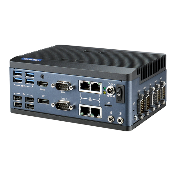
Page 18: Introduction
Introduction The following sections feature and installation guide and detail the external connector pin assignments for applications. Connectors 2.2.1 EPC-C301 External I/O HDMI DC IN LAN1 USB 3.0 COM1 ON/OFF LAN2 LAN4 COM2 Line Out USB 2.0 LAN3 COM4 CAN1 COM3 CAN2 Figure 2.1 EPC-C301 I/O... - Page 19 2.2.1.1 Power On/Off Button EPC-C301 has a Power On/Off button on the front side. Figure 2.2 Power On/Off Button 2.2.1.2 LED Indicators There are two LEDs on the front panel that indicate system status: The Power LED is for system power status; and HDD LED is for HDD and compact flash disk status. Figure 2.3 LED 2.2.1.3 HDMI Connector...
- Page 20 2.2.1.4 DP Connector Display port support DP1.2 up to 4096x2306 @60Hz (Note: does not support audio stream, hot-plug, or HDCP) Pin Name ML_Lane0(p) ML_Lane0(n) ML_Lane1(p) ML_Lane1(n) ML_Lane2(p) ML_Lane2(n) ML_Lane3(p) ML_Lane3(n) CONFIG1 CONFIG2 AUX CH(p) AUX CH(n) Hot Plug Detect +3.3V EPC-C301 User Manual...
- Page 21 2.2.1.5 USB 3.0 Connector EPC-C301 USB ports 1, 2, 3, and 4 support USB 3.0 interfaces.These facilitate plug- and-play functionality and hot swapping. USB 3.0 connectors contain legacy pins for interfacing with USB 2.0 devices. These connectors also feature a new set of pins for USB 3.0 connectivity (both sets reside on the same connector).
- Page 22 2.2.1.6 RJ45 (2 port) EPC-C301 User Manual...
- Page 23 Signal Pin Definition LAN1_MDIO+ LAN1_MDIO- LAN1_MDI1+ LAN1_MDI1- LAN1CONN LAN1_GND LAN1_MDI2+ LAN1_MDI2- LAN1 MDI3+ LAN1_MDI3- LAN1_ACT# LAN1_A_ACT# LAN1_A_LINK100# LAN1_A_LINK1000# LAN2_MDIO+ LAN2_MDIO- LAN2_MDI1+ LAN2_MDI1- LAN2CONN LAN2_GND LAN2_MDI2+ LAN2_MDI2- LAN2_MDI3+ LAN2_MDI3- LAN2_ACT# LAN2_A_ACT# LAN2_A_LINK100# LAN2_A_LINK1000# 2.2.1.7 Audio Connectors EPC-C301 offers stereo audio ports via two phone jack connectors called Line_Out, Mic_In.
- Page 24 2.2.1.8 COM Connector EPC-C301 provides 4x D-sub 9-pin connectors. COM1, COM2, and COM3 supports Full RS232-422-485. COM4 supports RS-232 only. PinPin Signal Pin Definition 422TX-/485D-/DCD# 422TX+/485D+/RXD 422RX+/TXD 422RX-/DTR# DSR# RTS# CTS# 2.2.1.9 Digital In-put/Output (DIO) Connector EPC-C301 provides 8 bit GPIO. For further details, please refer to the pin definition. Signal Name GPIO0 GPIO1...
- Page 25 2.2.1.10 CAN Bus Connector EPC-C301 provide 2 CANBus. It supports CAN 2.0B at 1Mb/s. Figure 2.6 CANBus Connector Pin Definition Pin Name Isolated GND EPC-C301 User Manual...
-
Page 26: Installation
Installation 2.3.1 M.2 2230 Module Installation Unscrew the 5 screws on the bottom of the case to remove the bottom cover. Install the M.2 2230 module in to the M.2 E-Key socket. Fix the M.2 module using the screws in the zip-lock bag and replace the bottom cover screws. -
Page 27: 3042 Module Installation
2.3.2 M.2 3042 Module Installation Unscrew the 5 screws on the bottom of the case and remove the bottom cover. Install the M.2 3042 module in to the M.2 B-Key socket. Fix the M.2 module with screws from the zip-lock bag and replace the bottom cover using the screws. -
Page 28: Minipcie Module Installation
2.3.3 MiniPCIe Module Installation Unscrew the 5 screws on the bottom of the case and remove the bottom cover. Install the MiniPCIe module in to the MiniPCIe socket. Fix the MiniPCIe module with a screw from the zip-lock bag and replace the bot- tom cover using the screws. -
Page 29: Wall Mount Bracket Installation
2.3.4 Wall Mount Bracket Installation Loosen the four screws (M3x10L) on the bottom of the case. Lock two wall mount brackets with these four screws. 1960092790N001 1930005269 Desserrez les quatre vis (M3x10L) du boîtier inférieur. Verrouillez deux supports de montage mural avec ces quatre vis. 2.3.5 DIN Rail Installation (default installation) Loosen the 3 Din rail screws on the back cover. - Page 30 EPC-C301 User Manual...
-
Page 31: Chapter 3 Bios Settings
Chapter BIOS Settings... - Page 32 AMIBIOS has been integrated into various motherboards for decades. Using the AMIBIOS Setup program, users can modify BIOS settings and control various sys- tem features. This chapter describes the basic navigation of the EPC-C301 BIOS setup screens. AMI BIOS ROM has a built-in Setup program that allows users to modify basic sys- tem configurations.
-
Page 33: Entering Setup
BIOS supports your CPU. If there is no number assigned to the patch code, please contact an Advantech application engineer to obtain an up-to-date patch code file. This will ensure that your CPU's system status is valid. -
Page 34: Advanced Bios Features Setup
3.1.2 Advanced BIOS Features Setup Select the Advanced tab from the EPC-C301 setup screen to enter the Advanced BIOS Setup screen. You can select any of the items in the left frame of the screen, such as CPU Configuration, to go to the sub menu for that item. You can display an Advanced BIOS Setup option by highlighting it using the <Arrow>... - Page 35 3.1.2.1 CPU Configuration C6DRAM Enable/Disable moving of dram contents to PRM memory when CPU is in C6 state. SW Guard Extension (SGX) Enable/Disable Software Guard Extensions (SGX). Select Owner EPOCH input type Choose Owner EPOCH modes. CPU Flex Ratio Override ...
- Page 36 Intel Trusted Execution Technology Enables utilization of additional hardware capabilities provided by Intel® Trusted Execution Technology. 3.1.2.2 Power & Performance CPU - Power Management Control CPU - Power Management Control Options. GT - Power Management Control GT - Power Management Control Options. EPC-C301 User Manual...
- Page 37 CPU - Power Management Control Boot Performance mode Select the performance state that the BIOS will set before OS handoff. Intel® SpeedStep™ Allows more than two frequency ranges to be supported. Intel® Speed Shift Technology Enable/Disable Intel® Speed Shift Technology support. HDC Control ...
- Page 38 CPU Lock Configuration CPU Lock Configuration. View/Configure Turbo Options Energy Efficient P-state Enable/Disable Energy Efficient P-state feature. Package Power Limit MSR Lock Enable/Disable locking of Package Power Limit settings. Energy Efficient Turbo Enable/Disable Energy Efficient Turbo feature. EPC-C301 User Manual...
- Page 39 Config TDP Configurations Configurable TDP Boot Mode Configurable TDP Mode as Nominal/Up/Down/Deactivate TDP selection. Configurable TDP Lock Configurable TDP Mode Lock sets the Lock bit. CTDP BIOS control Enables CTDP control via runtime ACPI BIOS method. EPC-C301 User Manual...
- Page 40 Power Limit 3 Settings Power Limit 3 Override Enable/Disable Power Limit 3 override. EPC-C301 User Manual...
- Page 41 CPU Lock Configuration CFG Lock Configure MSR 0xE2[15], CFG Lock bit. Overclocking Lock Enable/Disable Overclocking Lock (BIT 20) in FLEX_RATIO(194) MSR. EPC-C301 User Manual...
- Page 42 GT - Power Management Control RC6(Render Standby) Check to enable render standby support. Maximum GT frequency Maximum GT frequency limited by user. Disable Turbo GT frequency Enabled/Disabled Turbo GT frequency. EPC-C301 User Manual...
- Page 43 3.1.2.3 PCH-FW Configuration ME State When Disabled ME will be put ME into Temporarily Disabled Mode. Manageability Features State Enable/Disable Intel® Manageability features. AMT BIOS Features When disabled, AMT BIOS Features are no longer supported and user is no longer able to access MEBx setup.
- Page 44 3.1.2.4 ACPI Settings Enable ACPI Auto Configuration Enable or disable BIOS ACPI auto configuration. Enable Hibernation Enables or Disables System ability to Hibernate (OS/S4 Sleep State). This option may be not effective with some OS. ACPI Sleep State ...
- Page 45 3.1.2.5 iManager Configuration CPU Shutdown Temperature Enable/Disable CPU Shutdown Temperature. Power Saving Mode Enable/Disable power saving mode. Serial Port 1 Configuration Set Parameters of Serial Port 1. Serial Port 2 Configuration Set Parameters of Serial Port 2. Serial Port 3 Configuration ...
- Page 46 Serial Port 1 Configuration Serial Port Enable or Disable Serial Port (COM). Change Settings Select an optimal settings for Serial Port device. COM Port Mode COM Port Mode Select. EPC-C301 User Manual...
- Page 47 Serial Port 2 Configuration Serial Port Enable or Disable Serial Port (COM). Change Settings Select an optimal settings for Serial Port device. COM Port Mode COM Port Mode Select. EPC-C301 User Manual...
- Page 48 Serial Port 3 Configuration Serial Port Enable or Disable Serial Port (COM). Change Settings Select an optimal settings for Serial Port device. COM Port Mode COM Port Mode Select. EPC-C301 User Manual...
- Page 49 Serial Port 4 Configuration Serial Port Enable or Disable Serial Port (COM). Change Settings Select an optimal settings for Serial Port device. EPC-C301 User Manual...
- Page 50 Hardware Monitor Watchdog Timer Configuration Watchdog Timer Enable or Disable Watch Dog Timer Function. EPC-C301 User Manual...
- Page 51 GPIO Configuration GPIO0/1/2/3/4/5/6/7 Configure GPIO0/1/2/3/4/5/6/7. EPC-C301 User Manual...
- Page 52 3.1.2.6 ACPI Report Method Configuration ACPI Report Method Control Select ACPI Reporting Method for EC Devices. Active High-Speed COM Port Select to Enable High-Speed COM Port or Standard COM Port. ACPI Report Method for I2C Bus Select ACPI Reporting Method for EC I2C Bus. ACPI Report Method for SMBus ...
- Page 53 3.1.2.7 Trusted Computing Security Device Support Enable or disable BIOS support for security device. SHA-1 PCR Bank Enable or Disable SHA-1 PCR Bank. SHA256 PCR Bank Enable or Disable SHA256 PCR Bank. Pending operation Schedule an Operation for the Security Device. Platform Hierarchy ...
- Page 54 3.1.2.8 S5 RTC Wake Settings Wake system from S5 Enable or disable System wake on alarm event. Select FixedTime, system will wake on the hr::min::sec specified. EPC-C301 User Manual...
- Page 55 3.1.2.9 Serial Port Console Redirection Console Redirection This item allows users to enable or disable console redirection for Microsoft Windows Emergency Management Services (EMS). Console Redirection This item allows users to configuration console redirection detail settings. EPC-C301 User Manual...
- Page 56 3.1.2.10 Intel® TXT Information Intel® TXT Information Display Intel TXT information. EPC-C301 User Manual...
- Page 57 3.1.2.11 USB Configuration Legacy USB Support Enables Legacy USB support. AUTO option disables legacy support if no USB devices are connected. DISABLE option will keep USB devices available only for EFI applications. XHCI Hand-off This is a workaround for OSes without XHCI hand-off support. The XHCI owner- ship change should be claimed by XHCI driver.
- Page 58 3.1.2.12 CSM Configuration CSM Support Enable/Disable CSM Support. GateA20 Active UPON REQUEST - GA20 can be disabled using BIOS services. ALWAYS - do not allow disabling GA20; this option is useful when any RT code is executed above 1MB. INT19 Trap Response ...
- Page 59 3.1.2.13 NVMe Configuration 3.1.2.14 SDIO Configuration SDIO Access Mode Select access SD device in DMA mode or PIO mode. EPC-C301 User Manual...
- Page 60 3.1.2.15 Network Stack Configuration Network Stack Enable/Disable UEFI Network Stack. EPC-C301 User Manual...
-
Page 61: Chipset Configuration
3.1.3 Chipset Configuration Select the Chipset tab from the EPC-C301 setup screen to enter the Chipset BIOS Setup screen. You can display a Chipset BIOS Setup option by highlighting it using the <Arrow> keys. All plug-and-play BIOS Setup options are described in this sec- tion. - Page 62 3.1.3.1 System Agent (SA) Configuration Memory Configuration Memory Configuration Parameters. Graphics Configuration Graphics Configuration Parameters. VT-d VT-D capability. Above 4GB MMIO BIOS assignment Enable/Disable above 4GB Memory Mapped IO BIOS assignment. X2APIC Opt Out Enable/Disable X2APIC Opt Out Bit. EPC-C301 User Manual...
- Page 63 Memory Configuration Max TOLUD Maximum Value of TOLUD. Memory Scrambler Enable/Disable Memory Scrambler support. Force ColdReset Force ColdReset OR Choose MrcColdBoot mode. Memory Remap Enable/Disable Memory Remap above 4GB. EPC-C301 User Manual...
- Page 64 Graphics Configuration Graphics Turbo IMON Current Graphics turbo IMON current values supported. Internal Graphics Keep IGFX enabled based on the setup options. GTT Size Select the GTT Size. Aperture Size Select the Aperture Size. DVMT Pre-Allocated ...
- Page 65 3.1.3.2 PCH I/O Configuration PCI Express Configuration PCI Express Configuration Settings. SATA And RST Configuration SATA Device Options Settings. USB Configuration USB Configuration Settings. Security Configuration Security Configuration Settings. HD Audio Configuration HD Audio Subsystem Configuration Settings. SerialIO Configuration ...
- Page 66 LAN3 PXE ROM Enable or Disable onboard LAN's PXE option ROM. Onboard LAN4 Controller Enable or Disable onboard NIC. LAN4 PXE ROM Enable or Disable onboard LAN's PXE option ROM. PCIE Wake Enable or Disable PCIE to wake the system from S5. State After S3 ...
- Page 67 SATA and RST Configuration SATA Controller(s) Enable/Disable SATA Device. SATA Mode Selection Determine how SATA controller operate. SATA Controller Speed Indicates the maximum speed the SATA controller can support. Software Feature Mask Configuration RST Legacy ROM/RST UEFI Driver will refer to the SWFM configuration to enable/disable the storage feature.
- Page 68 USB Configuration XHCI Disable Compliance Mode Option to disable Compliance Mode. USB Port Disable Override Selectively Enable/Disable the corresponding USB Port from reporting a Device Connection to the Controller. EPC-C301 User Manual...
- Page 69 Security Configuration RTC Lock Enable will lock bytes 38h-3Fh in the lower/upper 128-byte bank of RTC RAM. BIOS Lock Enable or Disable the PCH BIOS Lock Enable feature. Force unlock on all GPIO pads If Enabled BIOS will force all GPIO pads to be in unlock state. EPC-C301 User Manual...
- Page 70 HD Audio Configuration HD Audio Control Detection of the HD-Audio device. Disabled = HDA will be uncondition- ally disabled. Enabled = HDA will be unconditionally Enabled. EPC-C301 User Manual...
- Page 71 Serial IO Configuration I2C0 Controller Enable/Disables Serial IO Controller. SCS Configuration eMMC 5.0 Controller Enable or Disable SCS eMMC 5.0 Controller. EPC-C301 User Manual...
-
Page 72: Security
3.1.4 Security Select Security Setup from the EPC-C301 Setup main BIOS setup menu. All Security Setup options, such as password protection and virus protection are described in this section. To access the sub menu for the following items, select the item and press <Enter>: Change Administrator / User Password ... -
Page 73: Boot
3.1.5 Boot Setup Prompt Timeout Number of seconds that the firmware will wait before initiating the original default boot selection. A value of 0 indicates that the default boot selection is to be initiated immediately on boot. A value of 65535(0xFFFF) indicates that firm- ware will wait for user input before booting. -
Page 74: Save & Exit
3.1.6 Save & Exit Save Changes and Exit This item allows you to exit system setup after saving the changes. Discard Changes and Exit This item allows you to exit system setup without saving any changes. Save Changes and Reset ... -
Page 75: Appendix A Watchdog Timer Sample Code
Appendix Watchdog Timer Sample Code... -
Page 76: Ec Watchdog Timer Sample Code
EC Watchdog Timer Sample Code EC_Command_Port = 0x29Ah EC_Data_Port = 0x299h Write EC HW ram = 0x89 Watch dog event flag = 0x57 Watchdog reset delay time = 0x5E Reset event = 0x04 Start WDT function = 0x28 ==================================================== .model small .486p .stack 256 .data... -
Page 77: Appendix B System Assignments
Appendix System Assignments... -
Page 78: System I/O Ports
System I/O Ports Addr. Range (Hex) Device 00h-1Fh DMA Controller 20h-2Dh Interrupt Controller 2Eh-2Fh Motherboard resources 30h-3Dh Interrupt Controller 40h-43h Timer/Counter 4Eh-4Fh Motherboard resources 50h-53h Timer/Counter 60h-6Fh 8042 (keyboard controller)/NMI Controller/Microcontroller 70h-7Fh Real-time Controller 80h-8Fh Debug Port/Reserved 90h-9Fh Debug Port/Reset Generator A0h-ADh Interrupt Controller B0h-B1h Interrupt Controller B4h-BDh Power Management... -
Page 79: Dma Channel Assignments
DMA Channel Assignments Channel Function 0 Available 1 Available 2 Available 3 Available 4 Direct memory access controller 5 Available 6 Available 7 Available 1st MB Memory Map Addr. Range (Hex) Device E0000h - FFFFFh System board D0000h - DFFFFh PCI Bus C0000h - CFFFFh System board A0000h - BFFFFh PCI Bus A0000h - BFFFFh Intel®... - Page 80 No part of this publication may be reproduced in any form or by any means, electronic, photocopying, recording or otherwise, without prior written permis- sion from the publisher. All brand and product names are trademarks or registered trademarks of their respective companies. © Advantech Co., Ltd. 2020...
Need help?
Do you have a question about the EPC-C301 Series and is the answer not in the manual?
Questions and answers