Table of Contents
Advertisement
Quick Links
Advertisement
Table of Contents

Subscribe to Our Youtube Channel
Related Manuals for Advantech EPC-S201


Summary of Contents for Advantech EPC-S201
- Page 1 User Manual EPC-S201 Fanless Embedded PC...
- Page 2 There is an English user manual included as a PDF file on the web- site. Please disregard the Chinese hard copy user manual if the product is not to be sold and/or installed in China. EPC-S201 User Manual...
- Page 3 The documentation and the software included with this product are copyrighted 2017 by Advantech Co., Ltd. All rights are reserved. Advantech Co., Ltd. reserves the right to make improvements in the products described in this manual at any time without notice.
-
Page 4: Declaration Of Conformity
Because of Advantech’s high quality-control standards and rigorous testing, most of our customers never need to use our repair service. If an Advantech product is defec- tive, it will be repaired or replaced at no charge during the warranty period. For out- of-warranty repairs, you will be billed according to the cost of replacement materials, service time and freight. -
Page 5: Technical Support And Assistance
Technical Support and Assistance Visit the Advantech web site at www.advantech.com/support where you can find the latest information about the product. Contact your distributor, sales representative, or the Advantech customer ser- vice center for technical support if you need additional assistance. Please have the following information ready before you call: –... -
Page 6: Ordering Information
Power cable 3-pin 183 cm, Europe type 1700000237-01 Power cable 3-pin 183 cm, PSE type EWM-W135F01E WIFI Module: 802.11 a/b/g/n, Atheros AR9382, 2T2R 1750008717-01 External Antenna, Dipole Ant. D.B 2.4/5G WIFI 3dBi 1750006043 SMA Cable, R-SMA(F)/MHF 1.32 150mm *Optional: default not included EPC-S201 User Manual... -
Page 7: Safety Instructions
Replacement of a BATTERY with an incorrect type that can defeat a SAFE- GUARD (for example, in the case of some lithium BATTERY types); Disposal of a BATTERY into fire or a hot oven, or mechanically crushing or cutting of a BATTERY, can result in an EXPLOSION; EPC-S201 User Manual... - Page 8 L'utilisateur Si l'une des situations suivantes se présente, faites vérifier l'équipement par le personnel de service: Le cordon d'alimentation ou la fiche est endommagé. Le liquide a pénétré dans l'équipement. EPC-S201 User Manual viii...
- Page 9 645 du Code national de l'électricité et à la norme NFPA 75 AVIS DE NON-RESPONSABILITÉ: Cet ensemble d'instructions est conforme à la norme CEI 704-1. Advantech décline toute responsabilité concernant l'exacti- tude des déclarations contenues dans ce document. EPC-S201 User Manual...
- Page 10 EPC-S201 User Manual...
-
Page 11: Table Of Contents
1.3.1 Functional Specification ..............3 1.3.2 WISE-PaSS/RMM................. 4 Mechanical Specifications................. 4 1.4.1 EPC-S201 Dimensions ..............4 Figure 1.1 EPC-S201 Mechanical Dimension Drawing ....4 1.4.2 Weight................... 4 Power Requirement .................. 4 1.5.1 System Power................4 1.5.2 RTC Battery .................. 4 Environment Specification................. - Page 12 Security..................41 Figure 3.20 Security Settings ............. 41 3.2.5 Boot .................... 42 3.2.6 Save & Exit ................. 43 Figure 3.21 Save & Exit.............. 43 Appendix A Watchdog Timer Sample Code ..45 Watchdog Timer Sample Code............... 46 EPC-S201 User Manual...
- Page 13 Appendix B SUSI API Introduction .......49 SUSI API Introduction ................50 B.1.1 The Watchdog API..............50 B.1.2 The Hardware Monitor API ............50 xiii EPC-S201 User Manual...
- Page 14 EPC-S201 User Manual...
-
Page 15: Chapter 1 General Introduction
Chapter General Introduction This chapter gives background information on the EPC-S201 series. -
Page 16: Introduction
Palm-sized system dimensions are designed to let users perform installation in space limited environments. EPC-S201 supports up to 2 COM port, offers 2 USB 3.0 , 1 GbE LAN , 1 x MINIPCIe, 1x mSATA for storage, and 1 SO-DIMM Memory socket for an extension module which provides multiple choice for satisfying different kind of usage for users. -
Page 17: Display
Audio Codec: Realtek ALC888S: Compliant with HD Audio specifications Audio Supports 16/20/24-bit DAC and 16/20/24-bit ADC resolution Supports: Line-out, Line-in Audio Connectors: Ear Phone Jack * 2 Battery backup BATTERY 3V/210 mAh with WIRE x 1 EPC-S201 User Manual... -
Page 18: Wise-Pass/Rmm
System information Running HR / Boot record Mechanical Specifications 1.4.1 EPC-S201 Dimensions 139 x 100 x 44 Unit: mm [Inch] Dimensions Unit : mm Figure 1.1 EPC-S201 Mechanical Dimension Drawing 1.4.2 Weight 0.6kg Power Requirement 1.5.1 System Power Minimum power input: DC 12V, 5A 1.5.2... -
Page 19: Environment Specification
Desk/Wall Mount/ DIN Rail: 3 Grms, IEC 60068-2-64, random vibration, 5 ~ 500 Hz, 1 hr/axis 1.6.5 Shock during Operation 30G, IEC60068-2-27, half sine, 11m duration 1.6.6 Safety UL, CB, CCC, BSMI 1.6.7 CE, FCC, CCC, BSMI, VCCI EPC-S201 User Manual... - Page 20 EPC-S201 User Manual...
-
Page 21: Chapter 2 H/W Installation
Chapter H/W Installation This chapter introduces the exter- nal I/O and the installation of EPC- S201 hardware. -
Page 22: Introduction
2.2.1 Jumper Description You may configure EPC-S201 to match the needs of your application by setting jump- ers. A jumper is a metal bridge used to close an electric circuit. It consists of two metal pins and a small metal clip (often protected by a plastic cover) that slides over the pins to connect them. -
Page 23: Jumper List
Jumper Setting On the Motherboard Auto Power On Setting Part Number 1653003260 Footprint HD_3x2P_79 Description PIN HEADER 3x2P 2.0mm 180D(M) SMD SOURCE PIN Setting Function Power On by power button (default) (1-2) (3-4) +3.3V (5-6) AT Mode EPC-S201 User Manual... -
Page 24: I/O Introduction
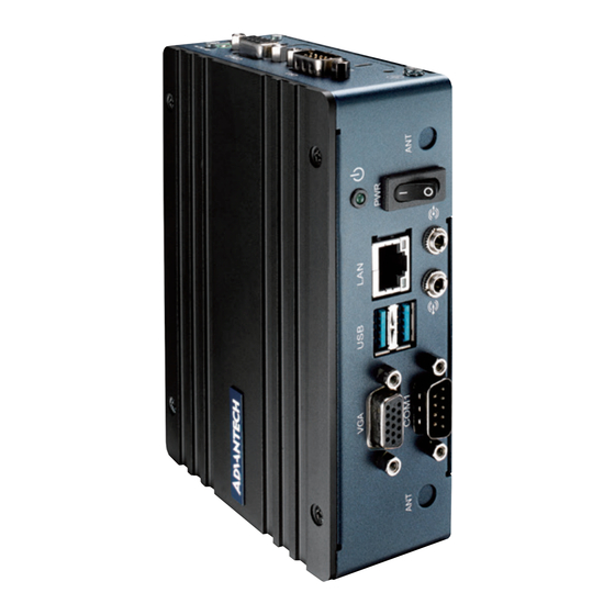
Figure 2.3 EPC-S201 Rear View EPC-S201 External I/O 2.4.1 Power On/Off Button EPC-S201 has a Power On/Off switch button on the front side that shows On status (I) and Off/Suspend status (O). Figure 2.4 Power On/Off Switch Button 2.4.2 Power Input Connector EPC-S201 is designed with the phoenix connector and 12DC input. -
Page 25: Ethernet Connector (Lan)
2.4.3 Ethernet Connector (LAN) EPC-S201 is equipped with two Ethernet controllers that are fully compliant with IEEE 802.3u 10/100/1000 Mbps CSMA/CD standards. LAN1, LAN2 are all equipped with i210 Ethernet controller. The Ethernet port provides a standard RJ-45 jack con- nector with LED indicators on the front side to show its Active/Link status (Green LED) and Speed status (Yellow LED). -
Page 26: Audio Connector
USB1_SSTX- USB1_SSTX+ 2.4.5 Audio Connector EPC-S201 offers stereo audio ports by two phone jack connectors of Line Out, Line In. The audio chip is controlled by ALC888S, and it’s compliant with the Azalea stan- dard. Figure 2.8 Audio Connector Table 2.4: Audio Connector Pin Definition... -
Page 27: Com Connector
NC represents “No Connection”. 2.4.7 HDMI Connector EPC-S201 offers a SKU that supports the HDMI port. This 19-pin receptacle connec- tor has a HDMI 1.4a interface. The HDMI link supports resolutions of up to 3840 x 2160 @ 30 Hz. -
Page 28: Power Led Indicators
DDP0_HPD NC represents “No Connection”. 2.4.8 Power LED Indicators EPC-S201 provides one LED on the front panel that indicates power status. Figure 2.11 Power LED Indicators 2.4.9 Antenna Hole EPC-S201 reserves two antenna holes for wireless antenna installation. Each of antenna holes is marked “ANT”... -
Page 29: Digital In-Put/Output (Dio) Connector
VGA CRT monitor. It supports display resolutions of up to 2048 x 1280 @ 60Hz. Figure 2.14 VGA Connector Table 2.8: VGA Connector Pin Definition Signal Name VGA_z_R VGA_z_G VGA_z_B VGA_z_SPC GND_RGB GND_RGB GND_RGB VGA_z_SPD VGA_z_DDAT EPC-S201 User Manual... -
Page 30: Installation
VGA_z_HS VGA_z_VS VGA_z_DCLK GND_IO GND_IO NC represents “No Connection”. Installation 2.5.1 Memory Installation Loosen screws, open TOP case. Figure 2.15 Loosen Screws, Open TOP Case Install memory and tighten up the screws again. Figure 2.16 Install Memory EPC-S201 User Manual... -
Page 31: Ram Installation
Figure 2.17 Loosen Screws, Open Bottom Case Install mSATA or miniPCIe module. We suggest to install mSATA in CTOS. (*mSATA and miniPCIe module are not included, demonstration only). mSATA miniPCIe modules Replace the bottom case and screw the four screws back on. EPC-S201 User Manual... -
Page 32: Din Rail Installation (Optional)
Use Din rail screws to mount Din rail. 2.5.4 Wall Mount Installation (Optional) Loosen four side screws of the top case (M3x5L) and screw back with the wall mount bracket. Screw down the four wall mount screws (M3x5L) to the table. EPC-S201 User Manual... -
Page 33: Chapter 3 Bios Settings
Chapter BIOS Settings... -
Page 34: Bios Setup
AMI BIOS has been integrated into a plethora of motherboards for decades. With the AMI BIOS Setup program, you can modify BIOS settings and control the various sys- tem features. This chapter describes the basic navigation of the EPC-S201 BIOS setup screens. -
Page 35: Entering Setup
BIOS supports your CPU. If there is no number assigned to the patch code, please contact an Advantech application engineer to obtain an up-to-date patch code file. This will ensure that your CPU‘s system status is valid. -
Page 36: Advanced Bios Features Setup
3.2.2 Advanced BIOS Features Setup Select the Advanced tab from the EPC-S201 setup screen to enter the Advanced BIOS Setup screen. You can select any of the items in the left frame of the screen, such as CPU Configuration, to go to the sub menu for that item. You can display an Advanced BIOS Setup option by highlighting it using the <Arrow>... -
Page 37: Figure 3.4 Acpi Setting
(*This option may be not effective with some OS.). ACPI Sleep State This item allows users to set the ACPI sleep state. Lock Legacy Resources This item allows users to lock legacy device resources. EPC-S201 User Manual... -
Page 38: Figure 3.5 First Serial Port Configuration(Sch3114)
Super I/O Configuration First Super I/O Configuration (SCH3114) Figure 3.5 First Serial Port Configuration(SCH3114) – Serial Port 1 Configuration Set Parameters of Serial Port 1 (COMA). – Serial Port 2 Configuration Set Parameters of Serial Port 2 (COMB). EPC-S201 User Manual... - Page 39 3.2.2.3 Hardware Monitor PC Health Status This page displays all the information about system Temperature/Voltage. Watch Dog Timer Enabled or Disabled Watch Dog Timer function. EPC-S201 User Manual...
- Page 40 Serial Port Console Redirection Console Redirection This item allows users to enable or disable console redirection for Microsoft Windows Emergency Management Services (EMS). Console Redirection This item allows users to configuration console redirection detail settings. EPC-S201 User Manual...
-
Page 41: Figure 3.6 Cpu Configuration
Number of cores to enable in each processor package. Intel Virtualization Technology When enabled, a VMM can utilize the additional hardware capabilities provided by Vanderpool Technology. Monitor Mwait Enable/Disable Monitor Mwait. VT-d Enable/Disable CPU VT-d. P-STATE Coordination Change P-STATE Coordination type. EPC-S201 User Manual... -
Page 42: Figure 3.7 Network Configuration Settings
3.2.2.6 Network Stack Configuration Figure 3.7 Network Configuration Settings Network Stack Enable/Disable UEFI Network Stack. EPC-S201 User Manual... -
Page 43: Figure 3.8 Csm Configuration Settings
Storage Controls the execution of UEFI and Legacy Storage OpROM. Video Controls the execution of UEFI and Legacy Video OpROM. Other PCI devices Determines OpROM execution policy for devices other than Network, Storage, or Video. EPC-S201 User Manual... - Page 44 Maximum time the device will take before it properly reports itself to the Host Controller. 'Auto' uses default value: for a Root port it is 100 ms, for a Hub port the delay is taken from Hub descriptor. EPC-S201 User Manual...
-
Page 45: Figure 3.9 Security Configuration Settings
3.2.2.9 Security Configuration Figure 3.9 Security Configuration Settings TXE EOP Message Send EOP message before entering OS EPC-S201 User Manual... -
Page 46: Chipset Configuration
Chipset Configuration Figure 3.10 Chipset Configuration North Bridge Details for North Bridge items. South Bridge Details for South Bridge items. Uncore Configuration Detail for Uncore items. South Cluster Configuration Detail for South Cluster items EPC-S201 User Manual... -
Page 47: Figure 3.11 North Bridge Configuration
3.2.3.1 North Bridge Figure 3.11 North Bridge Configuration Max TOLUD Maximum value of TOLUD. 3.2.3.2 South Bridge Figure 3.12 South Bridge Configuration EPC-S201 User Manual... -
Page 48: Figure 3.13 Uncore Configuration
DVMT Pre-Allocated Select DVMT 4.0 Pre-Allocated (UMA) Graphics Memory size used by the Inter- nal Graphics Device. DVMT Total Gfx Mem Select DVMT5.0 Total Graphic Memory size used by the Internal Graphics Device. GT PM Support EPC-S201 User Manual... -
Page 49: Figure 3.14 South Cluster Configuration
HD-Audio Configuration HD-Audio Configuration Settings. PCI Express Configuration PCI Express Configuration Settings. SATA Drives Press <Enter> to select the SATA Device Configuration Setup options. USB Configuration USB Configuration Settings. Miscellaneous Configuration Enable/Disable Misc. Features. EPC-S201 User Manual... -
Page 50: Figure 3.15 Hd-Audio Configuration Settings
HD-Audio Configuration Settings Figure 3.15 HD-Audio Configuration Settings HD-Audio Support Enable/Disable HD-Audio Support. 3.2.3.5 LPSS Configuration EPC-S201 User Manual... -
Page 51: Figure 3.16 Pci Express Configuration
Onboard LAN1 Controller Select to Enable or Disable Onboard LAN1 Controller. – LAN Option ROM Enabled / Disabled Onboard LAN’s PXE option ROM. – PCIE Wake from S5 Enable or disable PCIE to wake the system from S5. EPC-S201 User Manual... -
Page 52: Figure 3.17 Sata Drives Settings
SATA Drives Figure 3.17 SATA Drives Settings – Chipset SATA Enable or Disable the Chipset SATA Controller. EPC-S201 User Manual... -
Page 53: Figure 3.18 Usb Configuration Settings
Selectively Enable/Disable the corresponding USB port from reporting a Device Connection to the controller. – XHCI Disable Compliance Mode Options to disable XHCI Link Compliance Mode. Default is FALSE to not dis- able Compliance Mode. Set TRUE to disable Compliance Mode. EPC-S201 User Manual... -
Page 54: Figure 3.19 Miscellaneous Configuration Settings
BIOS Lock Enable/Disable the SC BIOS Lock Enable feature. – RTC Lock Enable or disable bytes 38h-3Fh in the upper and lower 128-byte bank of RTC RAM lockdown. – TCO SMI Lock Enable TCO and Lock Down TCO. EPC-S201 User Manual... -
Page 55: Security
Security Figure 3.20 Security Settings Select Security Setup from the EPC-S201 Setup main BIOS setup menu. All Security Setup options, such as password protection and virus protection are described in this section. To access the sub menu for the following items, select the item and press <Enter>:... -
Page 56: Boot
Sets the system boot order. Fast Boot Enable or Disable FastBoot features. Most probes are skipped to reduce time cost during boot. New Boot Option Policy Controls the placement of newly detected UEFI boot options. EPC-S201 User Manual... -
Page 57: Save & Exit
This item allows you to save the changes done so far as user defaults. Restore User Defaults This item allows you to restore the user defaults to all the options. Boot Override Boot device select can override your boot priority. EPC-S201 User Manual... - Page 58 EPC-S201 User Manual...
-
Page 59: Appendix A Watchdog Timer Sample Code
Appendix Watchdog Timer Sample Code... -
Page 60: Watchdog Timer Sample Code
;==================================================== ;66H ;WDT timer time-out value ;bit[7:0]=0~255 ;==================================================== mov dx,SCH3114_IO + 66h mov al,01h out dx,al ;==================================================== ;bit[0] status bit R/W ;WD timeout occurred =1;WD timer counting = 0 ;==================================================== mov dx,SCH3114_IO + 68h EPC-S201 User Manual... - Page 61 .exit EPC-S201 User Manual...
- Page 62 EPC-S201 User Manual...
- Page 63 Appendix SUSI API Introduction...
-
Page 64: Susi Api Introduction
Application programmers can invoke the functions exported by SUSI instead of call- ing the drivers directly. The benefit of using SUSI is portability. The same set of APIs is defined for different Advantech hardware platforms. Also, the same API set is implemented in different Operating Systems. This user's manual describes some sample programs and the API in SUSI. - Page 65 EPC-S201 User Manual...
- Page 66 No part of this publication may be reproduced in any form or by any means, electronic, photocopying, recording or otherwise, without prior written permis- sion of the publisher. All brand and product names are trademarks or registered trademarks of their respective companies. © Advantech Co., Ltd. 2018...
Need help?
Do you have a question about the EPC-S201 and is the answer not in the manual?
Questions and answers