
Subscribe to Our Youtube Channel
Related Manuals for Advantech ECU-4574 Series


Summary of Contents for Advantech ECU-4574 Series
- Page 1 User Manual ECU-4574 Series ® Intel ATOM E3930 Power and Energy Computers with 8 x LAN, 10 x COM...
- Page 2 No part of this manual may be reproduced, copied, translated, or transmitted in any form or by any means without the prior written permission of Advantech Co., Ltd. The information provided in this manual is intended to be accurate and reliable.
- Page 3 Product Warranty (2 years) Advantech warrants the original purchaser that each of its products will be free from defects in materials and workmanship for two years from the date of purchase. This warranty does not apply to any products that have been repaired or altered by persons other than repair personnel authorized by Advantech, or products that have been subject to misuse, abuse, accident, or improper installation.
- Page 4 3.5 mm screw. The equipment does not include a power cord and plug. DISCLAIMER: These instructions are provided according to IEC 704-1 standards. Advantech disclaims all responsibility for the accuracy of any statements contained herein. ECU-4574 User Manual...
- Page 5 Safety Precautions - Static Electricity Follow these simple precautions to protect yourself from harm and the products from damage. To avoid electrical shock, always disconnect the power from the PC chassis before manual handling. Do not touch any components on the CPU card or other cards while the PC is powered on.
- Page 6 ECU-4574 User Manual...
-
Page 7: Table Of Contents
Contents Chapter Overview..........1 Introduction ....................2 Hardware Specifications ................3 1.2.1 General ..................3 1.2.2 System Hardware ................. 3 1.2.3 I/O Interface .................. 3 1.2.4 Environment.................. 3 Safety Precautions ..................4 Chassis Dimensions.................. 4 Figure 1.1 ECU-4574 Chassis Dimensions ......... 4 Packing List.................... - Page 8 ECU-4574 User Manual viii...
-
Page 9: Chapter 1 Overview
Chapter Overview This chapter provides an overview of ECU-4574 Series’ specifica- tions. Sections include: Introduction Hardware Specifications Safety Precautions Chassis Dimensions Packing List... -
Page 10: Introduction
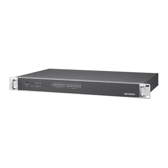
ECU-4574 is Intel Atom E3930 1.3 GHz Power & Energy Automation Computer with 8 x LAN and 10 x COM. ECU-4574 series products is compliant with Electricity Certif- icate IV level (especially for China), which provide higher reliability and stability, suit- able for any Global Power &... -
Page 11: Hardware Specifications
Hardware Specifications 1.2.1 General Certification: CE, FCC Class A, CCC, Electricity IV level for China (Compatible IEC61850-3, IEEE 1613) Dimensions (W x D x H): 440 x 220 x 44 mm Enclosure: SECC & Aluminum Mounting: 1U Rack mount ... -
Page 12: Safety Precautions
Caution! Always ground yourself to remove any static electric charge before touching ECU-4574 Series Modern electronic devices are very sensitive to static electric charges. Use a grounding wrist strap at all times. Place all electronic components on a static-dissipative surface or in a static- shielded bag. -
Page 13: Packing List
Packing List The accessory package of ECU-4574 Series contains the following items: ECU-4574-A64SCE accessory: (A) ECU-4574-A64SCE (B) 4 x 10PIN green screw terminals (C) 20 x 2P 2.0mm jumper shorter (D) 1 x 4PIN green screw terminals (E) 1 x cable for dual power module... - Page 14 ECU-4574 User Manual...
-
Page 15: Chapter 2 Hardware Function
Chapter Hardware Function This chapter shows how to setup the ECU-4574 hardware functions, including connecting peripherals, setting jumpers and indicators. Sections include: Overview LED Indicators Interface Definitions Power Input... -
Page 16: Overview
Overview The following figures show the indicators and connectors on ECU-4574 Series. The following sections give you detailed information about function of each peripheral. Figure 2.1 ECU-4574-A64SCE Front Panel Figure 2.2 ECU-4574-A64SCE Rear Panel Figure 2.3 ECU-4574-A64DCE Rear Panel LED Indicators The LEDs in the front panel can be divided into 3 groups. -
Page 17: Lan Status Indicators
2.2.2 LAN Status Indicators Table 2.2: Definition of LAN Status Indicators Item Status Description Green 1Gbps network link LAN/LINK Orange 100Mbps network link Port 1~8 10Mbps network link or invalid network link Green Ethernet data being received/ transmitted LAN/ACT Port 1~8 No Ethernet data being received/ transmitted 2.2.3 Serial Communication Status Indicators... -
Page 18: Power Input
Power Input ECU-4574 Series product support single power input AC or DC, It is reserved for dual power supply input interface, to facilitate customer to extend using dual power speci- fications. Table 2.4: AC/DC power input Item AC/DC Volt. Range... -
Page 19: Jumper Setup
Jumper Setup Serial port COM9-COM10 mode selection. CN10, CN13 RS-232 RS-422/RS-485 ECU-4574 User Manual... - Page 20 COM1-10 RS-485/RS-232 terminal resistance setup instructions. Add 120 ohm terminal resistor on TX+/TX- of RS-485 CN12, CN14, CN16, CN18, Add 300 ohm terminal resistor on TX+/TX- of RS-485 CN20, CN22, CN24, CN26, CN28, CN31 Add 120 ohm terminal resistor on RX+/RX- of RS-422 (optional) Add 300 ohm terminal resistor on Rx+/RX- of RS-422 (optional) COM Port Jumper for Terminal Resistor...
- Page 21 Clear CMOS. Normal work (Default) Clear CMOS ECU-4574 User Manual...
- Page 22 ECU-4574 User Manual...
-
Page 23: Chapter 3 Initial Setup
Chapter Initial Setup Sections include: Configuration Installing a mSATA card Installing Hard Disk... -
Page 24: Configuration
Configuration To open the ECU-4574 product chassis, remove all power and signal connections. And unscrew screws on the chassis’s top cover. Installing a m-SATA Card The ECU-4574 provides 1 m-SATA Card slot. To install the cards, open the product chassis and insert the card at location shown below ECU-4574 User Manual... -
Page 25: Installing A Hard Disk
Installing a Hard Disk To install a HDD and HDD bracket (in the accessory), unscrew the 4 screws and remove the HDD back plate. ECU-4574 User Manual... - Page 26 ECU-4574 User Manual...
-
Page 27: Appendix A Pin Assignments
Appendix Pin Assignments... -
Page 28: Rs-232 Serial Ports (Com9 ~ Com10)
RS-232 Serial Ports (COM9 ~ COM10) Table A.1: RS-232 Port Pin Definitions (COM9 ~ COM10) Pins RS-232 RS-232/485 Serial Ports (COM1 ~ COM8) Table A.2: RS-232/485 Serial Ports (COM1 ~ COM8) RS-232 RS-485 Pins Name Pins Name — — — Data+ —... -
Page 29: Vga
Table A.3: VGA Pins Signal Pins Signal + 5V Green Blue DDC-DATA H-SYNC V-SYNC DDC-CLK ECU-4574 User Manual... -
Page 30: Dvi-I
DVI-I Table A.4: DVI Signal TMDS_C2# TMDS_C2 CRT_DDC_CLK CRT_DDC_DATA MDVI_CLK MDVI_DATA VGAVSY TMDS_C1# TMDS_C1 VCC_DVI VGA Detect HP_DET TMDS_C0# TMDS_C0 TMDS_CK# TMDS_CK VGAR VGAG VGAB VGAHSY ECU-4574 User Manual... -
Page 31: Usb
Table A.5: USB 2.0 Pins Signal +V5 (VCC) USB DATA- USB DATA+ Power Loss Alarm Table A.6: Power Loss Alarm Wiring Pin Definition Pins Function Description 1-2 PWR1 FAIL Connected 3-4 PWR2 FAIL Connected ECU-4574 User Manual... - Page 32 No part of this publication may be reproduced in any form or by any means, such as electronically, by photocopying, recording, or otherwise, without prior written permission from the publisher. All brand and product names are trademarks or registered trademarks of their respective companies. © Advantech Co., Ltd. 2021...
Need help?
Do you have a question about the ECU-4574 Series and is the answer not in the manual?
Questions and answers