Table of Contents
Advertisement
Advertisement
Table of Contents

Related Manuals for Physiomed vocaSTIM-Master


Summary of Contents for Physiomed vocaSTIM-Master
- Page 1 O P E R A T I N G I N S T R U C T I O N S vocaSTIM -Master ® 00910 GB...
- Page 2 The technical data in this manual is as at the time of printing and subject to alteration. Copyright © 2000 - 2012 by PHYSIOMED ELEKTROMEDIZIN AG All rights, including rights of translation, reproduction by printing, copying or similar methods, even of parts are reserved.
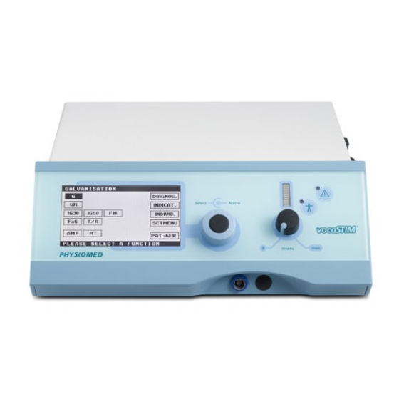
- Page 3 Instrument Overview Front Panel Rear Face Right Side Legend Mains Module Intensity Control Manual Release Key Socket Upper Status Bar Pulse Indicator Foot Switch Socket Display Patient Current Indicator Card Reader Lower Status Bar Output Indicator Data Selector Patient Lead Connector Symbols CAUTION! Please refer to the operating instructions and consider the physiological effects!
-
Page 5: Table Of Contents
Contents Introduction ........................1 Instrument Description ......................1 Application ..........................1 Contraindications ........................2 Controls and Indicators ....................3 Function of controls and indicators ..................3 2.1.1 Mains Module <1> ........................3 2.1.2 Upper Status Bar<2> ........................4 2.1.3 Display <3> ..........................4 2.1.4 Lower Status Bar <4>... - Page 6 Indications Menu ......................30 Individual Programs ..................... 33 Save Therapy Modes ......................33 Call Program ..........................34 Delete Program ........................35 vocaCARD ........................35 Save Card Programs .......................35 Direct Access to Card Programs .....................36 Prescribe Therapies / Therapy Check ..................36 Patient Device (Trainer) ....................39 10 Basic Settings ........................
-
Page 7: Introduction
Introduction 1 Introduction With your , you have acquired a high-quality and extremely vocaSTIM®-Master versatile unit for stimulation current therapy. The instrument will only show its true potential, however, if you are well informed Operating Instructions about its functions. For this reason, carefully read the familiarise yourself with the use of the instrument. -
Page 8: Contraindications
Introduction 1.3 Contraindications Contraindications to stimulation current therapy: • Highly inflammatory, fever-prone disorders • Pregnancy • Patients with cardiac pacemakers or other implanted stimulators • Malignant tumours • Spastic paralysis • Skin lesions of the area to be treated • Implants containing metal parts within the area of treatment vocaSTIM -Master... -
Page 9: Controls And Indicators
Controls and Indicators 2 Controls and Indicators As its LCD is divided in different function fields, allows for clear vocaSTIM®-Master and easy operation. The plastic housing and the front panel protect the electronic components and simplify cleaning. Safety-related components are continuously monitored by the microprocessor, erroneously initiated operating steps are suppressed, a self-test routine is performed after switching on and possible malfunctions are displayed. -
Page 10: Upper Status Bar<2
Controls and Indicators 2.1.2 Upper Status Bar<2> The upper status bar <2> shows indications or some of the corresponding parameters selected. For example: GALVANISATION 2.1.3 Display <3> Upper Status Bar Display Lower Status Bar On the display <3>, you can select all of the instrument’s menus and parameters on different levels except for the intensity. -
Page 11: Intensity Control <6
Controls and Indicators 2.1.6 Intensity Control <6> The intensity control <6> serves to set the intensity in steps of 0.1 mA. When turning up the intensity control <6> the therapy timer on the display <3> will be started as well. Every time you have to turn down the intensity control to 0, the following message will be displayed in the lower... -
Page 12: Output Indicator <9
Controls and Indicators accessories of the corresponding circuit should be checked and replaced if necessary. 2.1.9 Output Indicator <9> This indicator tells you to be cautious when handling the electrodes: Warning! The patient lead connector <10> and the electrodes are under voltage! Attach or remove the electrodes only after the intensity control <6>... -
Page 13: Manual Release Key Socket <11
Controls and Indicators 2.1.11 Manual Release Key Socket <11> The manual release key socket <11> serves to connect a manual release key for manually triggering the current pulse. The use of a manual release key may be appropriate when applying the current modes . -
Page 14: Overview Of Parameters
Controls and Indicators 2.2 Overview of Parameters 2.2.1 Start Menu (1 level) Upper Status Bar <2> Diagnostics Menu Low-frequency Indications Menu Current Modes (direct access) Individual Programs Basic Settings Medium-frequency Current Modes (direct access) Lower Status Bar <4> Patient Device Mode 2.2.2 Example Menu (2 level) Current Mode... -
Page 15: Operation
Controls and Indicators 2.3 Operation Selecting a function (e.g. the current mode ) from the start menu (level 1) will lead you to level 2 of the menu. Here you can set the desired parameters for the selected current mode. The following functions are available on level 2: Memory menu;... - Page 16 Controls and Indicators Current Mode medium-frequency Switching from galvanic current to interrupted direct current . The current setting is displayed in the upper status bar. Current Modes UR, Switching from monophase pulses with galvanic basis to biphase pulses. The current setting is displayed in the upper status bar.
- Page 17 Controls and Indicators 5 pre-set frequency bands, fixed frequency (SELECT 0 – 250 Hz) Basic frequency (possible values: 2.0 – 9.5 kHz) Current Mode Intensity display, to be set with intensity control <6> Tension time T (possible values: 1 to 60 s in steps of manual release key (only if R >...
-
Page 18: Characterisation Of The Individual Current Modes
Controls and Indicators 2.4 Characterisation of the Individual Current Modes 2.4.1 Low-frequency Current Modes (LF) Galvanisation Direct current without any interruption or break. Variation: Medium-frequency interrupted direct current (8 kHz; duty cycle 95%). Application: Iontophoresis, basic therapy for paralysis and atrophy treatment, evoking hyperaemia Note You have to take special care when applying galvanic current. - Page 19 Controls and Indicators (IG 30) P ulse Galvanisation 30 acc. to Jantsch Fixed parameters Adjustable Pulse shape: triangular Mono-/biphase T = pulse time: 30 ms R = release time: 50 ms Stimulation frequency: approx. 12 monophase biphase with galvanic basis 5% Application: Circulatory stimulation, analgesia (IG 50) P...
- Page 20 Controls and Indicators (FM) Frequency-Modulated Current Fixed parameters Adjustable Pulse shape: triangular Mono-/biphase T = pulse time: 1 ms R = release time: 70 -142 ms Stimulation frequency: 7 -14 Hz monophase biphase with galvanic basis 5% Application: Shiver-inducing frequency with automatically altered stimulation cycles for circulatory stimulation, relaxing muscle tensions, analgesia with little sensitive strain (FaS)
-
Page 21: Medium-Frequency Currents
Controls and Indicators (T/R) Pulses with Adjustable Parameters Fixed parameters Adjustable = basic frequency: 2.5 kHz Monophase/medium-frequency t = pulse time: 0.1 -1000 ms R = release time: 1, 3, 5s and manual triggering (manual release key). Pulse shapes: 1 square, 4 trapezoidal, 2 triangular, 2 exponential pulses Example monophase... -
Page 22: Current Modes Of The Diagnostics Menu
Controls and Indicators (MT) Medium-Frequency Muscle Training Fixed parameters Adjustable Sinusoidal waves T = contraction 1 – 60 s; manual triggering (manual release key) if R > R = release time between contractions 0 – 60 Ramp (surge time): 5 settings m –... -
Page 23: Notes On Operation
Notes on Operation 3 Notes on Operation 3.1 Connection (1) Check whether the operating voltage of the device (see red window in the mains module <1>) and the line voltage correspond. (2) Plug the supplied mains lead firmly into the rear panel of the device (mains module <1>) and connect it to the socket. -
Page 24: Instrument Errors
Notes on Operation 3.4 Instrument Errors If a functional error is detected during the automatic self-test routine or during operation, a corresponding note will be displayed on the LCD. A numeric error code will be shown, e. g. <ERROR 10>. The instrument will be switched off. These error codes simplify localising and eliminating errors. -
Page 25: Therapy
Therapy 4 Therapy This chapter provides you with general information on stimulation current therapy and notes on attaching the electrodes. Moreover, both peculiarities and operating steps are described for different modes of treatment with using vocaSTIM®-Master low-frequency currents (page 21) and medium-frequency currents (page 26). Warning Always switch on the equipment BEFORE you attach the electrodes to the patient! Only switch off the equipment off AFTER you have removed the... -
Page 26: Safety Precautions For Stimulation Current Intensity
Therapy 4.3 Safety Precautions for Stimulation Current Intensity Please observe the following safety precautions when adjusting the intensity of the stimulation current applied to the patient: • Always bear in mind that the patient may display an altered sensitivity, and may therefore not be properly aware of the current strength. -
Page 27: Modes Of Attaching The Electrodes
Therapy (5) Select the size of the electrodes according to the area of treatment following Area of electrodes as small as necessary but as large as possible the principle: A larger electrode area usually makes treatment for the patients more pleasant. (6) Plug the plate electrodes into the well-moistened electrode covers and attach them to the patient. -
Page 28: Iontophoresis
Therapy Monophase current modes resemble direct current, i.e. every electrode has a defined polarity: + = anode (low-stimulation electrode) - = cathode (high-stimulation electrode). Biphase current modes, however, have a continually alternating polarity, called polarity . The stimulation intensity of both electrodes is identical. Many current modes are preferably applied in biphase mode, as you can reduce the danger of burns even at high doses. -
Page 29: Pain Therapy, Hyperaemisation, Detonisation
Therapy Caution Take care that the electrodes are by no means touched after the current is turned up! (8) After treatment, an acoustic signal will be issued. Turn the intensity down to 0. (9) Remove the electrodes and rinse the viscose covers thoroughly. Note The diffused quantity of the agent directly depends on the size of the electrodes, the therapy time and the current intensity. -
Page 30: Muscle Stimulation Using Low-Frequency Currents
Therapy 4.5.4 Muscle Stimulation using Low-Frequency Currents For muscle stimulation use the low-frequency current modes FaS is usually applied in case of faradic excitable nervo-muscular systems. If, however, while testing the faradic excitability, it was noticed that the muscles can NOT be stimulated successfully any more, it is advisable to treat the beginning atrophy of the paralysed muscle with triangular pulses of the T/R. - Page 31 Therapy Caution Take care that the electrodes are by no means touched after the current is turned up! (11) Signs of fatigue should stop the treatment (they may already occur after a few muscle contractions)! (12) After treatment, an acoustic signal will be issued. Turn the intensity down to 0. (13) Remove the electrodes.
-
Page 32: Therapy Using Medium-Frequency Current Modes
Therapy automatically and will keep the set intensity as long as the manual release key is pressed. After releasing the button, the intensity will automatically be reduced in intervals. Pressing the button for will trigger a current pulse of the time T previously selected. If the intensity is turned up during release time, the Note following message appears in the lower status bar <4>:... -
Page 33: Muscle Stimulation Using Medium-Frequency Surge Current
Therapy 4.6.2 Muscle Stimulation using Medium-Frequency Surge Current The medium-frequency surge current intended for surge current therapy is . This current mode is usually applied to faradic excitable nerve-muscle units. Medium-Frequency Muscle Training Procedure (1) Prior to attaching the electrodes, make sure that the intensity control<6> is turned down to 0! (2) Attach the electrodes to the respective stimulation points. - Page 34 Therapy (5) Set the release time R > 1s and the tension time T to the left to the manual release key position. (6) Select the ramp of the current rise. (7) Select the frequency of modulation. (8) If necessary, alter the basic frequency. (9) Activate the acoustic signal, if desired.
-
Page 35: Diagnosis: Accommodation Quotient
Diagnosis: Accommodation Quotient 5 Diagnosis: Accommodation Quotient accommodation quotient Rheobase galvano-tetanus- is the quotient of threshold, i.e. of the intensities with square pulses (1000 or 500 ms) and triangle pulses (1000 or 500 ms) necessary to trigger a minimal contraction. It informs about the accommodation ability of the examined nerve-muscle unit and thus about its degree of damage. -
Page 36: Indications Menu
Indications Menu (12) The calculated accommodation quotient α and the respective evaluation are displayed in a diagram. (13) Turn the intensity down to 0. (14) If necessary, repeat the procedure with inverse polarity. Caution Always turn down the intensity control <6> to 0, before you unplug the foot switch from the device! 6 Indications Menu The indications menu offers you another possibility to start the individual methods... - Page 37 Indications Menu The therapy overview for the selected indication is shown: First treatment section with according parameters Second treatment section with according parameters Number of exercises to be concluded on the CD according to Pahn Field for selecting a graphical Field for activating representation of the electrode the therapy...
- Page 38 Indications Menu (9) Turn the intensity control <6> down to 0. (10) The parameters for the second treatment section are set. You may select the individual parameters to adjust them, if necessary. (11) If the manual release key has not yet been connected, connect it to the manual release key socket <11>.
-
Page 39: Individual Programs
Individual Programs 7 Individual Programs You do not have to set frequently applied forms of therapy every time you want to use them – you can simply save them as individual programs. Such a program is e.g. a certain current mode with all parameters including treatment time. You may save individual programs and restart them as well as delete and overwrite them. -
Page 40: Call Program
Individual Programs (10) For saving other current modes proceed as described under 1-8. (11) Exit the menu. The selected settings are saved in the respective program and can now be accessed. You can easily overwrite existing programs. Note For a better overview, the parameters saved for each position are shown. -
Page 41: Delete Program
vocaCARD 7.3 Delete Program Proceed as follows to delete a program: (1) Select a current mode on the display <3>. (2) Select the symbol programs and confirm. The menu individual programs will be displayed. (3) Select the program to be deleted with the data selector <5>... -
Page 42: Direct Access To Card Programs
vocaCARD (6) Select the symbol save vocaCARD and confirm. The symbol starts flashing. (7) Select one of the positions 1 or 2 and confirm (8) Turn the intensity control <6> back to 0. The current settings are now saved to the selected position. (9) Exit the menu via If required, save the parameters for another current mode. - Page 43 vocaCARD (3) Insert the into the card reader <13>. vocaCARD Previously saved prescriptions are shown on the display: Number of non-concluded treatments Number of prescribed Number of released treatments pulses Time for Sequence functional = Therapy Section exercises Total = Number of concluded treatments Delete The column...
- Page 44 vocaCARD (5) For deleting the total counters proceed as described under (1) – (3), click on the button Delete and confirm. A new window will be displayed. If you want to cancel the process, choose and confirm the selection; all data will remain on the vocaCARD If you want to delete all data from the...
-
Page 45: Patient Device (Trainer)
Patient Device (Trainer) 9 Patient Device (Trainer) The patient device function allows you to explain the operation of limited functions of the device to a patient so that he can conclude one or several treatments stored on the vocaCARD Proceed as follows to conclude a treatment in the patient device mode: on the display <3>... -
Page 46: Basic Settings
Basic Settings 10 Basic Settings In the basic settings, you can set different parameters that are rarely altered. Select the button from the display <3> to get to the basic settings. SETMENU The symbols have the following meaning: Contrast of the LCD Active menu when switching on the device (e. -
Page 47: Setup Menu
Basic Settings 10.1 Setup Menu The setup-menu allows for adjusting device settings without interrupting the selected function. The symbols have the following meaning: Volume and pitch of the therapy timer Contrast of the LCD Quit setup menu To modify a parameter, proceed as follows: (1) Press the icon in any menu. -
Page 48: General Notes
Repairs to the instrument may only be performed by parties duly authorised by . Any repairs performed by an authorised agent PHYSIOMED ELEKTROMEDIZIN AG must be accompanied by written certification, describing the nature and extent of the repairs undertaken, as applicable with details regarding changes to nominal operating values or the operational range. -
Page 49: Cleaning And Disinfection
Cleaning and Disinfection 13 Cleaning and Disinfection Clean your accessories and instrument on a regular basis with a disinfecting agent based on aldehyde. By any means, switch off the device prior to this and pull the mains plug. Use a soft sponge cloth for cleaning. Be careful that no liquid substances invade the instrument. -
Page 50: Accessories
Accessories 15 Accessories Warning For safety reasons, has to be used exclusively with original vocaSTIM ® -Master accessories. The use of other manufacturers' accessories is at the user's risk. Warning Plate electrodes are subject to wear and tear. The degree of wearout depends on the current mode, the frequency of use, and the intensity. -
Page 51: Additional Accessories
Accessories 15.2 Additional Accessories Ref.-No. Description 00465 Bergony mask (set) 00580 Connection cable for PHYSIOPADS adhesive elect. (pair, red/blue) 00228 Extension for patient lead (blue) 00227 Extension for patient lead (red) 00155 Grip handle for punctiform electrodes 00156 Grip handle for punctiform electrodes with pushbutton 00136 Iontophoresis foil 00596... - Page 52 Accessories 00149 Viscose cloth 00437 Viscose cover EF 100 00439 Viscose cover EF 200 vocaSTIM -Master ®...
-
Page 53: Manufacturer's Recommendations
UNIT: vocaSTIM ® -Master MANUFACTURER: PHYSIOMED ELEKTROMEDIZIN AG Instrument has to undergo a safety regulation control every 18 months. E X T E N T : Visual inspection of the instrument, extras and accompanying papers Function of controls and indicators... -
Page 54: Index
Index Index accessories with stimulation current 1 additional 45 diagnostics menu standard 44 current modes 16 accomodation quotient 16, 29 disinfecting agent 43 adjustable parameters (T/R) 15 disinfection 43 amplitude-modulated current (AMF) 15 display 4 analgesia 13 overview 8 anions 22 electrode application 1 different 21... - Page 55 Index maintenance 42 pulse galvanisation 13 malfunction 3 pulse indicator 5 manual release key pulse Jantsch 13 usage 25, 27 reaction time manual release key socket 7 foot switch 40 medium-frequency current modes 26 recommendations 47 medium-frequency currents 15 repair 42 menu resistance 5 example 8...
Need help?
Do you have a question about the vocaSTIM-Master and is the answer not in the manual?
Questions and answers