Table of Contents
Advertisement
SINAMICS V20 Inverter
SINAMICS
SINAMICS V20 Inverter
Operating Instructions
07/2012
A5E03728167
___________________
Preface
___________________
Safety instructions
___________________
Introduction
___________________
Mechanical installation
___________________
Electrical installation
___________________
Commissioning
___________________
Communicating with the PLC
___________________
Parameter list
___________________
Fault and warning codes
___________________
Technical specifications
___________________
Options and spare parts
1
2
3
4
5
6
7
8
A
B
Advertisement
Table of Contents

Related Manuals for Siemens SINAMICS V20 Series


Summary of Contents for Siemens SINAMICS V20 Series
- Page 1 ___________________ SINAMICS V20 Inverter Preface ___________________ Safety instructions ___________________ Introduction SINAMICS ___________________ Mechanical installation ___________________ SINAMICS V20 Inverter Electrical installation ___________________ Commissioning Operating Instructions ___________________ Communicating with the PLC ___________________ Parameter list ___________________ Fault and warning codes ___________________ Technical specifications ___________________ Options and spare parts 07/2012...
- Page 2 Note the following: WARNING Siemens products may only be used for the applications described in the catalog and in the relevant technical documentation. If products and components from other manufacturers are used, these must be recommended or approved by Siemens. Proper transport, storage, installation, assembly, commissioning, operation and maintenance are required to ensure that the products operate safely and without any problems.
-
Page 3: Preface
+39 (02) 24362000 Brazil +55 11 3833 4040 India +91 22 2760 0150 Korea +82 2 3450 7114 Turkey +90 (216) 4440747 +1 423 262 5710 Further service contact information: Support contacts (http://support.automation.siemens.com/WW/view/en/16604999) SINAMICS V20 Inverter Operating Instructions, 07/2012, A5E03728167... - Page 4 Preface SINAMICS V20 Inverter Operating Instructions, 07/2012, A5E03728167...
-
Page 5: Table Of Contents
Table of contents Preface ..............................3 Safety instructions ............................. 7 Introduction.............................. 13 Components of the inverter system .....................13 Inverter rating plate ........................14 Mechanical installation..........................15 Mounting orientation and clearance.....................15 Cabinet panel mounting (frame sizes A ... D) ................16 Push-through mounting (frame sizes B ... D)................18 Electrical installation .......................... - Page 6 Table of contents 5.6.2.4 Setting the PID controller ......................67 5.6.2.5 Setting the braking function......................69 5.6.2.6 Setting the ramp time ........................77 5.6.2.7 Setting the Imax controller ......................79 5.6.2.8 Setting the Vdc controller ......................81 5.6.2.9 Setting the load torque monitoring function ................82 5.6.3 Commissioning advanced functions ...................
-
Page 7: Safety Instructions
Safety instructions Before installing and putting this equipment into operation, read the following safety instructions and all warning labels attached to the equipment carefully. Make sure the warning labels are kept in a legible condition and replace missing or damaged labels. General DANGER Dangerous voltage... - Page 8 Safety instructions CAUTION Static discharges on surfaces or interfaces (e.g. terminal or connector pins) can cause malfunctions or defects. Therefore, when working with inverters or inverter components, ESD protective measures should be observed. Transport and storage CAUTION Protect the equipment from physical shocks or vibration during transport and storage. It is important that the equipment is protected from water (rainfall) and excessive temperatures.
- Page 9 Safety instructions CAUTION Separate the control cables from the power cables as much as possible. Keep the connecting cables away from rotating mechanical parts. Commissioning WARNING The following terminals can carry dangerous voltages even if the inverter is not operating: - The mains input terminals L1, L2, L3, and PE - The motor terminals U, V, W, and output earth terminal - The DC link terminals DC+ and DC-...
- Page 10 Repair WARNING Repairs on equipment may only be carried out by Siemens Service, by repair centers authorized by Siemens or by authorized personnel who are thoroughly acquainted with all the warnings and operating procedures contained in this manual. Any defective parts or components must be replaced using parts contained in the relevant spare parts lists.
- Page 11 Safety instructions Residual risks CAUTION The control and drive components of a power drive system (PDS) are approved for industrial and commercial use in industrial line supplies. Their use in public line supplies requires a different configuration and/or additional measures. These components may only be operated in closed housings or in higher-level control cabinets with protective covers that are closed, and when all of the protective devices are used.
- Page 12 Safety instructions SINAMICS V20 Inverter Operating Instructions, 07/2012, A5E03728167...
-
Page 13: Introduction
Introduction Components of the inverter system The SINAMICS V20 is a range of inverters designed for controlling the speed of three phase asynchronous motors. The inverter is available in four frame sizes. Frame size A Frame size C Frame size D Frame size B 3 AC 400 V variants Component... -
Page 14: Inverter Rating Plate
Introduction 2.2 Inverter rating plate Inverter rating plate Inverter rating plate (example) SINAMICS V20 Inverter Operating Instructions, 07/2012, A5E03728167... -
Page 15: Mechanical Installation
Mechanical installation Mounting orientation and clearance The inverter must be mounted in an enclosed electrical operating area or a control cabinet. Mounting orientation Always mount the inverter in an upright position. Mounting clearance ≥ 100 mm Bottom ≥100 mm (for frame sizes B ... D, and frame size A without fan) ≥... -
Page 16: Cabinet Panel Mounting (Frame Sizes A
Mechanical installation 3.2 Cabinet panel mounting (frame sizes A ... D) Cabinet panel mounting (frame sizes A ... D) You can mount the inverter directly on the surface of the cabinet panel. An additional mounting method is also available for different frame sizes. For more details, refer to the following section: ●... - Page 17 Mechanical installation 3.2 Cabinet panel mounting (frame sizes A ... D) Dimensions (mm) Drill pattern (mm) Frame size C Fixings: 4 x M5 screws 4 x M5 nuts 4 x M5 washers Tightening torque: 2.5 Nm ± 10% Frame size D Fixings: 4 x M5 screws 4 x M5 nuts...
-
Page 18: Push-Through Mounting (Frame Sizes B
Mechanical installation 3.3 Push-through mounting (frame sizes B ... D) Push-through mounting (frame sizes B ... D) The frame sizes B to D are designed to be compatible with "push-through" applications, allowing you to mount the heatsink of the inverter through the back of the cabinet panel. When the inverter is mounted as the push-through variant, no higher IP rating is achieved. - Page 19 Mechanical installation 3.3 Push-through mounting (frame sizes B ... D) Dimensions (mm) Drill pattern and cut-out (mm) Frame size D Fixings: 4 x M5 screws Tightening torque: 2.5 Nm ± 10% Depth inside the cabinet SINAMICS V20 Inverter Operating Instructions, 07/2012, A5E03728167...
- Page 20 Mechanical installation 3.3 Push-through mounting (frame sizes B ... D) Mounting NOTICE A gap is reserved at the bottom of the cut-out area to allow fan removal from outside the cabinet without removing the inverter. SINAMICS V20 Inverter Operating Instructions, 07/2012, A5E03728167...
-
Page 21: Electrical Installation
Electrical installation Typical system connections Typical system connections for 400 V variants SINAMICS V20 Inverter Operating Instructions, 07/2012, A5E03728167... - Page 22 Electrical installation 4.1 Typical system connections Recommended fuse types Frame size Recommended fuse type CE-compliant (Siba URZ) UL-compliant 400 V 50 124 34 (16 A) 15 A 600 VAC, class J 50 124 34 (20 A) 20 A 600 VAC, class J 50 140 34 (30 A) 30 A 600 VAC, class J 50 140 34 (63 A)
-
Page 23: Terminal Description
Electrical installation 4.2 Terminal description Terminal description Terminal layout - 400 V variants User terminals: SINAMICS V20 Inverter Operating Instructions, 07/2012, A5E03728167... - Page 24 Electrical installation 4.2 Terminal description Recommended cable cross-sections and screw tightening torques Frame size Rated output Cable cross-section Screw tightening torque (tolerance: ± 10%) power Mains and PE terminals Motor / DC / braking resistor / output earth terminals 400 V 0.37 ...
- Page 25 Electrical installation 4.2 Terminal description User terminals Terminal Description marking 10 V output (tolerance ± 5 %) referred to 0V, maximum 11 mA, short circuit protected Analog Mode: AI1: Single-ended, bipolar current and voltage inputs mode AI2: Single-ended, unipolar current and voltage mode Isolation to control circuit: None...
- Page 26 Electrical installation 4.2 Terminal description Terminal Description marking Response time: 4 ms ± 4 ms Pulse train input: 24 V output (tolerance - 15 % ... + 20 %) referred to 0 V, maximum 50 mA, non- isolated Overall reference potential for digital inputs Digital DO1 + Mode:...
-
Page 27: Emc-Compliant Installation
Electrical installation 4.3 EMC-compliant installation EMC-compliant installation EMC-compliant installation of the inverter The screening plate kit is supplied as an option for each frame size (For more information about this option, see Appendix "Screening plate kit (Page 260)".). It allows easy and efficient connection of the necessary screening to achieve EMC-compliant installation of the inverter. -
Page 28: Emc-Compliant Cabinet Design
Electrical installation 4.4 EMC-compliant cabinet design EMC-compliant cabinet design The most cost-effective method of implementing interference suppression measures within the control cabinet is to ensure that interference sources and potentially susceptible equipment are installed separately from each other. The control cabinet has to be divided into EMC zones and the devices within the control cabinet have to be assigned to these zones following the rules below. -
Page 29: Commissioning
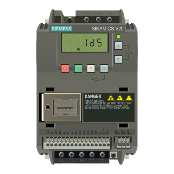
Commissioning NOTICE For a detailed description of parameter settings for the quick commissioning, refer to the topic "Quick commissioning (Page 38)". The built-in Basic Operator Panel (BOP) 5.1.1 Introduction to the built-in BOP Hz Hz 1/min 1/min kW Button functions Stops the inverter Single press OFF1 stop reaction: the inverter brings the motor to a standstill in the ramp-... - Page 30 Commissioning 5.1 The built-in Basic Operator Panel (BOP) Multi-function button Short press ( < 2 s) Enters the parameter setting menu or moves to the next screen • Restarts the digit by digit editing on the selected item • If pressed twice in digit by digit editing, returns to the previous screen •...
-
Page 31: Inverter Menu Structure
Commissioning 5.1 The built-in Basic Operator Panel (BOP) 5.1.2 Inverter menu structure Inverter menu structure Menu Description 50 / 60 Hz selection menu This menu is visible only on first power-up or after a factory reset. Main menu Display menu (default display) Basic monitoring view of key parameters such as frequency, voltage, current, DC-link voltage, and so on Setup menu... -
Page 32: Viewing Inverter Status
Commissioning 5.1 The built-in Basic Operator Panel (BOP) 5.1.3 Viewing inverter status The display menu provides a basic monitoring view of some key parameters such as frequency, voltage, current, and so on. Parameter Menu Display Menu Setup Menu 5.1.4 Editing parameters This section describes how to edit parameters. - Page 33 Commissioning 5.1 The built-in Basic Operator Panel (BOP) Normal editing of parameters NOTICE Pressing for longer than two seconds to quickly increase or decrease the parameter numbers or indexes is only possible in the parameter menu. This editing method is best suited when small changes are required to parameter numbers, indexes, or values.
-
Page 34: Screen Displays
Commissioning 5.1 The built-in Basic Operator Panel (BOP) Example 1: Example 2: Example 3: Editing parameter numbers Editing parameter indices Editing parameter values If a parameter is an array, edit indices as illustrated below: 5.1.5 Screen displays The following two tables show you basic screen displays: Screen Display Meaning... - Page 35 Commissioning 5.1 The built-in Basic Operator Panel (BOP) Screen Display Meaning information Hexadecimal Parameter value in hex format number "bxx x" Parameter value in bit format "Fxxx" Fault code "Axxx" Alarm code "Cnxxx" Settable connection macro "-Cnxxx" Current selected connection macro "APxxx"...
-
Page 36: Led States
Commissioning 5.2 Checking before power-on 5.1.6 LED states The SINAMICS V20 only has one LED for status indications. The LED can display orange, green, or red. If more than one inverter state exists, the LED displays in the following priority order: ●... -
Page 37: Setting The 50 / 60 Hz Selection Menu
Commissioning 5.3 Setting the 50 / 60 Hz selection menu Setting the 50 / 60 Hz selection menu NOTICE The 50 / 60 Hz selection menu is visible only on first power-up or after a factory reset (P0970). You can make a selection using the BOP or exit the menu without making a selection and the menu will not be displayed unless a factory reset is performed. -
Page 38: Starting The Motor For Test Run
Commissioning 5.4 Starting the motor for test run Starting the motor for test run This section explains how to start the motor for a test run to check that the motor speed and rotation direction are correct. NOTICE To run the motor, the inverter must be in the display menu (default display) and power-on default state with P0700 (selection of command source) = 1. - Page 39 Commissioning 5.5 Quick commissioning Menu structure Parameter Menu Display Menu Setup Menu SINAMICS V20 Inverter Operating Instructions, 07/2012, A5E03728167...
-
Page 40: Setting Motor Data
Commissioning 5.5 Quick commissioning 5.5.1.2 Setting motor data Functionality This menu is designed for easy setup of nominal motor nameplate data. Text menu If you set P8553 to 1, parameter numbers in this menu are replaced with short text. Setting parameters NOTICE In the table below, "●"... -
Page 41: Setting Connection Macros
Commissioning 5.5 Quick commissioning Parameter Access Function Text menu level (if P8553 = 1) P0311[0] ● Rated motor speed [RPM] (M RPM) P1900 Select motor data identification = 0: Disabled = 2: Identification of all parameters in standstill (MOT ID) See also Parameter list (Page 117) 5.5.1.3... - Page 42 Commissioning 5.5 Quick commissioning Connection macro Description Display example Cn007 External push button with analog setpoint Cn008 PID control with analog input reference Cn009 PID control with the fixed value reference Cn010 USS control Cn011 MODBUS RTU control Setting connection macros Connection macro Cn001 - BOP as the only control source 10V AI1 AI2 0V DI1 DI2 DI3 DI4 DIC 24V 0V AO+ AO- DO1+ DO1-...
- Page 43 Commissioning 5.5 Quick commissioning Connection macro Cn002 - Control from terminals (PNP / NPN) External control - Potentiometer with setpoint ● Hand / Auto switch between the BOP and terminals by pressing ● Both NPN and PNP can be realized with the same parameters. You can change the connection of the digital input common terminal to 24 V or 0 V to decide the mode.
- Page 44 Commissioning 5.5 Quick commissioning Parameter Description Factory Default for Remarks default Cn002 P0703[0] Function of digital input 3 Fault acknowledgement P0704[0] Function of digital input 4 JOG forward P0771[0] CI: Analog output Actual frequency P0731[0] BI: Function of digital output 1 52.3 52.2 Inverter running...
- Page 45 Commissioning 5.5 Quick commissioning Parameter Description Factory Default for Remarks default Cn003 P1003[0] Fixed frequency 3 Speed high P0771[0] CI: Analog output Actual frequency P0731[0] BI: Function of digital output 1 52.3 52.2 Inverter running P0732[0] BI: Function of digital output 2 52.7 52.3 Inverter fault active...
- Page 46 Commissioning 5.5 Quick commissioning Parameter Description Factory Default for Remarks default Cn004 P0732[0] BI: Function of digital output 2 52.7 52.3 Inverter fault active Connection macro Cn005 - Analog input and fixed frequency The analog input works as an additional setpoint. ●...
- Page 47 Commissioning 5.5 Quick commissioning Parameter Description Factory Default for Remarks default Cn005 P0704[0] Function of digital input 4 Fault acknowledgement P1016[0] Fixed frequency mode Direct selection mode P1020[0] BI: Fixed frequency selection bit 0 722.3 722.1 P1021[0] BI: Fixed frequency selection bit 1 722.4 722.2 P1001[0]...
- Page 48 Commissioning 5.5 Quick commissioning Parameter Description Factory Default for Remarks default Cn006 P0732[0] BI: Function of digital output 2 52.7 52.3 Inverter fault active P1040[0] Setpoint of the MOP Initial frequency P1047[0] MOP ramp-up time of the RFG Ramp-up time from zero to maximum frequency P1048[0] MOP ramp-down time of the RFG...
- Page 49 Commissioning 5.5 Quick commissioning Parameter Description Factory Default for Remarks default Cn007 P0727[0] Selection of 2 / 3-wire method 3-wire STOP + Forward pulse + Reverse pulse P0771[0] CI: Analog output Actual frequency P0731[0] BI: Function of digital output 1 52.3 52.2 Inverter running...
- Page 50 Commissioning 5.5 Quick commissioning Parameter Description Factory Default for Remarks default Cn008 P0731[0] BI: Function of digital output 1 52.3 52.2 Inverter running P0732[0] BI: Function of digital output 2 52.7 52.3 Inverter fault active Connection macro Cn009 - PID control with the fixed value reference 10V AI1 AI2 0V DI1 DI2 DI3 DI4 DIC 24V 0V AO+ AO- DO1+ DO1- P+ N-...
- Page 51 Commissioning 5.5 Quick commissioning Connection macro Cn010 - USS control 10V AI1 AI2 0V DI1 DI2 DI3 DI4 DIC 24V 0V AO+ AO- DO1+ DO1- P+ N- 220V 0~20mA= 0~50/60Hz Parameter Description Factory Default for Remarks default Cn010 P0700[0] Selection of command source RS485 as the command source P1000[0] Selection of frequency...
-
Page 52: Setting Application Macros
Commissioning 5.5 Quick commissioning Parameter Description Factory Default for Remarks default Cn011 P2021[0] MODBUS address MODBUS address for inverter P2022[0] MODBUS reply timeout 1000 1000 Maximum time to send reply back to the master P2014[0] USS / MODBUS telegram off time 2000 Time to receive data 5.5.1.4... - Page 53 Commissioning 5.5 Quick commissioning Setting application macros Application macro AP010 - Simple pump applications Parameter Description Factory Default for Remarks default AP010 P1080[0] Minimum frequency Inverter running at a lower speed inhibited P1300[0] Control mode Quadratic V/f P1110[0] BI: Inhibit negative frequency setpoint Reverse pump rotation inhibited P1210[0] Automatic restart...
- Page 54 Commissioning 5.5 Quick commissioning Parameter Description Factory Default for Remarks default AP020 P1080[0] Minimum frequency Inverter running at a lower speed inhibited P1120[0] Ramp-up time Ramp-up time from zero to maximum frequency P1121[0] Ramp-down time Ramp-down time from maximum frequency to zero Application macro AP021 - Compressor applications Parameter Description...
-
Page 55: Setting Common Parameters
Commissioning 5.5 Quick commissioning 5.5.1.5 Setting common parameters Functionality This menu provides some common parameters for inverter performance optimization. Text menu If you set P8553 to 1, parameter numbers in this menu are replaced with short text. Setting parameters Parameter Access Function Text menu... -
Page 56: Quick Commissioning Through The Parameter Menu
Commissioning 5.5 Quick commissioning Parameter Access Function Text menu level (if P8553 = 1) P1003[0] Fixed frequency setpoint 3 (FIX F3) P2201[0] Fixed PID frequency setpoint 1 (PID F1) P2202[0] Fixed PID frequency setpoint 2 (PID F2) P2203[0] Fixed PID frequency setpoint 3 (PID F3) 5.5.2 Quick commissioning through the parameter menu... - Page 57 Commissioning 5.5 Quick commissioning Parameter Function Setting P0305[0] ● Rated motor current [A] Range: 0.01 ... 10000 Note: The input of rating plate data must correspond with the wiring of the motor (star / delta) P0307[0] ● Rated motor power [kW / hp] Range: 0.01 ...
- Page 58 Commissioning 5.5 Quick commissioning Parameter Function Setting P1082[0] Maximum frequency [Hz] Range: 0.00 ... 599.00 (factory default: 50.00) Note: The value set here is valid for both clockwise and counter- clockwise rotation P1120[0] Ramp-up time [s] Range: 0.00 ... 650.00 (factory default: 10.00) Note: The value set here means the time taken for motor to accelerate from standstill up to the maximum motor frequency (P1082)
-
Page 59: Function Commissioning
Commissioning 5.6 Function commissioning Function commissioning 5.6.1 Overview of inverter functions The list below provides an overview of the main functions that the SINAMICS V20 supports. For detailed description of individual parameters, see Chapter "Parameter list (Page 117)". ● User access level control (P0003) ●... - Page 60 Commissioning 5.6 Function commissioning ● Motor brake controls (holding brake, DC brake, compound brake and dynamic brake) (P1212 ... P1237, see also "Setting the braking function (Page 69)".) ● DC-link voltage control (P0210, P1240 ... P1257, see also "Setting the Vdc controller (Page 81)".) ●...
-
Page 61: Commissioning Basic Functions
Commissioning 5.6 Function commissioning 5.6.2 Commissioning basic functions 5.6.2.1 Selecting the stop mode Functionality Both the inverter and the user have to respond to a wide range of situations and stop the inverter if needed. Thus operating requirements as well as inverter protective functions (e.g. electrical or thermal overload), or rather man-machine protective functions, have to be taken into account. - Page 62 Commissioning 5.6 Function commissioning OFF2 The inverter pulses are immediately cancelled by the OFF2 command. Thus the motor coasts down and it is not possible to stop in a controlled fashion. NOTICE • The OFF2 command can have one or several sources. The command sources are defined using BICO parameters P0844 (BI: 1.
-
Page 63: Running The Inverter In Jog Mode
Commissioning 5.6 Function commissioning NOTICE • OFF3 can be entered using a wide range of command sources via BICO parameters P0848 (BI: 1. OFF3) and P0849 (BI: 2. OFF3). • OFF3 is active low. • When simultaneously selecting the various OFF commands, the following priority applies: OFF2 (highest priority) –... -
Page 64: Setting The Voltage Boost
Commissioning 5.6 Function commissioning Setting parameters Parameter Function Setting P1055[0...2] BI: Enable JOG right This parameter defines source of JOG right when P0719 = 0 (Auto selection of command / setpoint source). Factory default: 19.8 P1056[0...2] BI: Enable JOG left This parameter defines source of JOG left when P0719 = 0 (Auto selection of command / setpoint source). - Page 65 Commissioning 5.6 Function commissioning Parameter Boost type Description P1310 Continuous boost [%] This parameter defines boost level relative to P0305 (rated motor current) applicable to both linear and quadratic V/f curves. Range: 0.0 ... 250.0 (factory default: 50.0) The voltage boost is effective over the complete frequency range whereby the value continually decreases at high frequencies.
- Page 66 Commissioning 5.6 Function commissioning Parameter Boost type Description P1312 Starting boost [%] This parameter applies a constant linear offset relative to P0305 (rated motor current) to active V/f curve (either linear or quadratic) after an ON command and is active until: ramp output reaches setpoint for the first time respectively •...
-
Page 67: Setting The Pid Controller
Commissioning 5.6 Function commissioning 5.6.2.4 Setting the PID controller Functionality The integrated PID controller (technology controller) supports all kinds of simple process control tasks, e.g. controlling pressures, levels, or flowrates. The PID controller specifies the speed setpoint of the motor in such a way that the process variable to be controlled corresponds to its setpoint. - Page 68 Commissioning 5.6 Function commissioning Parameter Function Setting Additional commissioning parameters P2251 PID mode = 0: PID as setpoint (factory default) = 1: PID as trim source P2253[0...2] CI: PID setpoint This parameter defines setpoint source for PID setpoint input. Possible sources: 755[0] (Analog input 1), 2018.1 (USS PZD 2), 2224 (Actual fixed PID setpoint), 2250 (Output setpoint of PID-MOP) P2254[0...2]...
-
Page 69: Setting The Braking Function
Commissioning 5.6 Function commissioning Parameter Function Setting P2355 PID tuning offset [%] Range: 0.00 ... 20.00 (factory default: 5.00) Output values r2224 CO: Actual fixed PID setpoint [%] r2225.0 BO: PID fixed frequency status r2245 CO: PID-MOP input frequency of the RFG [%] r2250 CO: Output setpoint of PID-MOP [%] r2260... - Page 70 Commissioning 5.6 Function commissioning The inverter pulses are inhibited after the braking time has expired. Sequence 2 1. Enabled and selected using BICO parameter P1230 (see figure below). 2. The inverter pulses are inhibited for the duration of the de-magnetizing time P0347. 3.
- Page 71 Commissioning 5.6 Function commissioning Setting parameters Parameter Function Setting P1230[0...2] BI: Enable DC braking This parameter enables DC braking via a signal applied from an external source. The function remains active while external input signal is active. Factory default: 0 P1232[0...2] DC braking current [%] This parameter defines level of DC current relative to rated...
- Page 72 Commissioning 5.6 Function commissioning Compound braking For compound braking (enabled using P1236), DC braking is superimposed with regenerative braking (where the inverter regenerates into the DC-link supply as it brakes along a ramp). Effective braking is obtained without having to use additional components by optimizing the ramp-down time (P1121 for OFF1 or when braking from f1 to f2, P1135 for OFF3) and using compound braking P1236.
- Page 73 Commissioning 5.6 Function commissioning NOTICE The compound braking depends on the DC link voltage only (see threshold in the above diagram). This will happen on OFF1, OFF3 and any regenerative condition. Compound braking is deactivated, if: • flying start is active •...
- Page 74 Commissioning 5.6 Function commissioning The continuous power P and the duty cycle for the braking resistor can be modified using the dynamic braking module (for frame size A / B / C) or parameter P1237 (for frame size D). WARNING The average power of the braking chopper cannot exceed the power rating of the braking resistor.
- Page 75 Commissioning 5.6 Function commissioning Parameter Function Setting P1254 Auto detect Vdc switch-on levels This parameter enables / disables auto-detection of switch-on levels for Vdc_max controller. = 0: Disabled = 1: Enabled (factory default) It is recommended to set P1254 = 1 (auto detection of Vdc switch-on levels enabled).
- Page 76 Commissioning 5.6 Function commissioning Setting parameters Parameter Function Setting P1215 Holding brake enable This parameter enables / disables holding brake function. The motor holding brake (MHB) is controlled via status word 1 r0052 bit 12. = 0: Motor holding brake disabled (factory default) = 1: Motor holding brake enabled P1216 Holding brake release delay[s]...
-
Page 77: Setting The Ramp Time
Commissioning 5.6 Function commissioning Connecting the motor holding brake The motor holding brake can be connected to the inverter via digital outputs (DO 1 / DO 2). An additional relay is also required to allow the digital output to enable or disable the motor holding brake. - Page 78 Commissioning 5.6 Function commissioning Setting parameters Parameter Function Setting P1082[0...2] Maximum frequency [Hz] This parameter sets maximum motor frequency at which motor will run irrespective of the frequency setpoint. Range: 0.00 ... 599.00 (factory default: 50.00) P1120[0...2] Ramp-up time [s] This parameter sets the time taken for motor to accelerate from standstill up to maximum motor frequency (P1082) when no rounding is used.
-
Page 79: Setting The Imax Controller
Commissioning 5.6 Function commissioning 5.6.2.7 Setting the Imax controller Functionality If ramp-up time is too short, the inverter may display the alarm A501 which means the output current is too high. The Imax controller reduces inverter current if the output current exceeds the maximum output current limit (r0067). - Page 80 Commissioning 5.6 Function commissioning Setting parameters You only have to change the factory default settings of the Imax controller if the inverter tends to oscillate when it reaches the current limit or it is shut down due to overcurrent. Parameter Function Setting P0305[0...2]...
-
Page 81: Setting The Vdc Controller
Commissioning 5.6 Function commissioning 5.6.2.8 Setting the Vdc controller Functionality If ramp-down time is too short, the inverter may display the alarm A911 which means the DC link voltage is too high. The Vdc controller dynamically controls the DC link voltage to prevent overvoltage trips on high inertia systems. -
Page 82: Setting The Load Torque Monitoring Function
Commissioning 5.6 Function commissioning Setting parameters Parameter Function Setting P1240[0...2] Configuration of Vdc controller This parameter enables / disables Vdc controller. = 0: Vdc controller disabled = 1: Vdc_max controller enabled (factory default) = 2: Kinetic buffering (Vdc_min controller) enabled = 3: Vdc_max controller and kinetic buffering (KIB) enabled Note: This parameter must be set to 0 (Vdc controller disabled) if a braking resistor is used. -
Page 83: Commissioning Advanced Functions
Commissioning 5.6 Function commissioning Parameter Function Setting P2182[0...2] Belt threshold frequency 1 [Hz] Range: 0.00 ... 599.00 (factory default: 5.00) P2183[0...2] Belt threshold frequency 2 [Hz] Range: 0.00 ... 599.00 (factory default: 30.00) P2184[0...2] Belt threshold frequency 3 [Hz] Range: 0.00 ... 599.00 (factory default: 30.00) P2185[0...2] Upper torque threshold 1 [Nm] Range: 0.0 ... - Page 84 Commissioning 5.6 Function commissioning Parameter Function Setting P3353[0...2] Super torque ramp time [s] This parameter defines the ramp time to be used when ramping up to the super torque frequency. Range: 0.0 ... 650.0 (factory default: 5.0) P3354[0...2] Super torque frequency [Hz] This parameter defines the frequency at which the additional boost is applied for super torque mode.
-
Page 85: Starting The Motor In Hammer Start Mode
Commissioning 5.6 Function commissioning 5.6.3.2 Starting the motor in hammer start mode Functionality This startup mode applies a sequence of torque pulses to start the motor. Typical application field Very sticky pumps Setting parameters Parameter Function Setting P3350[0...2] Super torque mode = 2: Enable hammer start mode Note: When the value of P3350 is changed, the value of P3353 is changed as follows:... - Page 86 Commissioning 5.6 Function commissioning Parameter Function Setting P3359[0...2] Hammer on time [ms] This parameter sets the time for which the additional boost is applied for each repetition (must be at least 3 x motor magnetization time). Range: 0..1000 (factory default: 300) P3360[0...2] Hammer off Time [ms] This parameter sets the time for which the additional boost is...
-
Page 87: Starting The Motor In Blockage Clearing Mode
Commissioning 5.6 Function commissioning 5.6.3.3 Starting the motor in blockage clearing mode Functionality This startup mode momentarily reverses the motor rotation to clear a pump blockage. Typical application field Pump clearing Setting parameters Parameter Function Setting P3350[0...2] Super torque mode = 3: Enable blockage clearing mode Note: When the value of P3350 is changed, the value of P3353 is changed as follows:... - Page 88 Commissioning 5.6 Function commissioning Parameter Function Setting P3363[0...2] Enable rapid ramp This parameter selects whether the inverter ramps to, or starts directly from, the blockage clearing frequency = 0: Disable rapid ramp for blockage clearing (use ramp time specified in P3353) = 1: Enable rapid ramp for blockage clearing (jump to the reverse frequency - this introduces a "kicking"...
-
Page 89: Running The Inverter In Economy Mode
Commissioning 5.6 Function commissioning 5.6.3.4 Running the inverter in economy mode Functionality Economy mode works by slightly changing the output voltage either up or down in order to find the minimum input power. NOTICE The economy mode optimization is only active when operating at the requested frequency setpoint. -
Page 90: Setting The Ul508C-Compliant Motor Overtemperature Protection
Commissioning 5.6 Function commissioning 5.6.3.5 Setting the UL508C-compliant motor overtemperature protection Functionality The function protects the motor from overtemperature. The function defines the reaction of the inverter when motor temperature reaches warning threshold. The inverter can remember the current motor temperature on power-down and reacts on the next power-up based on the setting in P0610. -
Page 91: Setting The Free Function Blocks (Ffbs)
Commissioning 5.6 Function commissioning 5.6.3.6 Setting the free function blocks (FFBs) Functionality Additional signal interconnections in the inverter can be established by means of free function blocks (FFBs). Every digital and analog signal available via BICO technology can be routed to the appropriate inputs of the free function blocks. The outputs of the free function blocks are also interconnected to other functions using BICO technology. -
Page 92: Setting The Flying Start Function
Commissioning 5.6 Function commissioning 5.6.3.7 Setting the flying start function Functionality The flying start function (enabled using P1200) allows the inverter to be switched onto a motor which is still spinning by rapidly changing the output frequency of the inverter until the actual motor speed has been found. -
Page 93: Setting The Automatic Restart Function
Commissioning 5.6 Function commissioning 5.6.3.8 Setting the automatic restart function Functionality After a power failure (F3 "Undervoltage"), the automatic restart function (enabled using P1210) automatically switches on the motor if an ON command is active. Any faults are automatically acknowledged by the inverter. When it comes to power failures (line supply failure), then a differentiation is made between the following conditions: ●... -
Page 94: Running The Inverter In Frost Protection Mode
Commissioning 5.6 Function commissioning 5.6.3.9 Running the inverter in frost protection mode Functionality If the ambient temperature falls below a given threshold, motor turns automatically to prevent freezing. ● OFF1 / OFF3: The frost protection function is disabled when OFF3 is activated and enabled again when OFF1 is activated. -
Page 95: Running The Inverter In Condensation Protection Mode
Commissioning 5.6 Function commissioning 5.6.3.10 Running the inverter in condensation protection mode Functionality If an external condensation sensor detects excessive condensation, the inverter applies a DC current to keep the motor warm to prevent condensation. ● OFF1 / OFF3: The condensation protection function is disabled when OFF3 is activated and enabled again when OFF1 is activated. -
Page 96: Running The Inverter In Sleep Mode
Commissioning 5.6 Function commissioning 5.6.3.11 Running the inverter in sleep mode Functionality The motor is turned off if demand falls below threshold, and turned on if demand rises above threshold. Setting parameters Parameter Function Setting P2365[0...2] Hibernation enable / disable This parameter enables or disables the hibernation functionality. -
Page 97: Setting The Wobble Generator
Commissioning 5.6 Function commissioning 5.6.3.12 Setting the wobble generator Functionality The wobble generator executes predefined periodical disruptions superimposed on the main setpoint for technological usage in the fiber industry. The wobble function can be activated via P2940. It is independent of the setpoint direction, thus only the absolute value of the setpoint is relevant. -
Page 98: Running The Inverter In Motor Staging Mode
Commissioning 5.6 Function commissioning Parameter Function Setting P2947 Wobble signal decrement step This parameter sets the value for decrement step at the end of the positive signal period. Range: 0.000 ... 1.000 (factory default: 0.000) P2948 Wobble signal increment step This parameter sets the value for the increment step at the end of the negative signal period. - Page 99 Commissioning 5.6 Function commissioning ⎛ ⎞ ⎜ ⎜ ⎟ ⎟ ⎝ ⎠ Destaging: 2378 ⋅ 1082 P1080 P1120 Δ -P2373 P2375 r2379 ⎛ ⎞ 2378 1080 ⎜ ⎜ − ⋅ ⎟ ⎟ 1120 ≤ P1080 ⎝ 1082 ⎠ Δ ≤ -P2373 >...
- Page 100 Commissioning 5.6 Function commissioning Setting parameters Parameter Function Setting P2370[0...2] Motor staging stop mode This parameter selects stop mode for external motors when motor staging is in use. = 0: Normal stop (factory default) = 1: Sequence stop P2371[0...2] Motor staging configuration This parameter selects configuration of external motors (M1, M2) used for motor staging feature.
-
Page 101: Running The Inverter In Cavitation Protection Mode
Commissioning 5.6 Function commissioning 5.6.3.14 Running the inverter in cavitation protection mode Functionality The cavitation protection will generate a fault / warning when cavitation conditions are deemed to be present. If the inverter gets no feedback from the pump transducer, it will trip to stop cavitation damage. -
Page 102: Setting The User Default Parameter Set
Commissioning 5.6 Function commissioning 5.6.3.15 Setting the user default parameter set Functionality The user default parameter set allows a modified set of defaults, different to the factory defaults, to be stored. Following a parameter reset these modified default values would be used. -
Page 103: Setting The Dual Ramp Function
Commissioning 5.6 Function commissioning 5.6.3.16 Setting the dual ramp function Functionality The dual ramp function allows the user to parameterize the inverter so that it can switch from one ramp rate to another when ramping up or down to a setpoint. This may be useful for delicate loads, where starting to ramp with a fast ramp-up or ramp-down time may cause damage. -
Page 104: Restoring To Defaults
Commissioning 5.7 Restoring to defaults Setting parameters Parameter Function Setting P1175[0...2] BI: Dual ramp enable This parameter defines command source of dual ramp enable command. If binary input is equal to one, then the dual ramp will be applied. The factory default value is 0. P1060[0...2] JOG ramp-up time [s] This parameter sets the JOG ramp-up time. -
Page 105: Communicating With The Plc
Communicating with the PLC The SINAMICS V20 supports communication with Siemens PLCs over USS on RS485. You can parameterize whether the RS485 interface shall apply USS or MODBUS RTU protocol. USS is the default bus setting. A screened twisted pair cable is recommended for the RS485 communication. - Page 106 Communicating with the PLC 6.1 USS communication The messages are always sent in the following format (half-duplex communication): …… n. LGE ADR 1. …… n. LGE ADR ● Response delay time: 20 ms ● Start delay time: depends on baud rate (minimum operation time for 2-character string: 0.12 ...
- Page 107 Communicating with the PLC 6.1 USS communication Request ID Description Response ID positive negative Modify parameter value (array, word) 7 / 8 Modify parameter value (array, double word) 7 / 8 Request number of array elements 7 / 8 Modify parameter value (array, double word) and store in EEPROM 7 / 8 Modify parameter value (array, word) and store in EEPROM 7 / 8...
- Page 108 Communicating with the PLC 6.1 USS communication Description Request is not included / task is not supported PKW request access timeout / number of retries is exceeded / wait for response from CPU side Parameter value cannot be changed (parameter is locked) 200 / 201 Changed lower / upper limits exceeded 202 / 203 No display on the BOP The available access authorization does not cover parameter changes...
-
Page 109: Modbus Communication
Communicating with the PLC 6.2 MODBUS communication Parameter Function Setting r2024[0] USS / MODBUS error statistics The state of the telegram information on RS485 is reported regardless of the protocol set in P2023. r2031[0] r2018[0...7] CO: PZD from USS / MODBUS on Displays process data received via USS / MODBUS on RS485 RS485. - Page 110 Communicating with the PLC 6.2 MODBUS communication FC6 - Write Single Register When a message with FC = 0 x 06 is received, then 4 bytes of data are expected, that is, FC6 has 4 bytes of data: ● 2 bytes for the register address ●...
- Page 111 Communicating with the PLC 6.2 MODBUS communication The table below shows the cases in which an Exception Code is returned: Error description Exception Code Unknown Function Code Read registers, which are out of boundary Write register, which is out of boundary Read request of too many registers (>125) Write request of too many registers (>123) Incorrect message length...
- Page 112 Communicating with the PLC 6.2 MODBUS communication Parameter Function Setting r2024[0] USS / MODBUS error statistics The state of the telegram information on RS485 is reported regardless of the protocol set in P2023. r2031[0] r2018[0...7] CO: PZD from USS / MODBUS on Displays process data received via USS / MODBUS on RS485 RS485.
- Page 113 Communicating with the PLC 6.2 MODBUS communication Register No. Description Acce Unit Scaling Range or On/Off Read Write factor text Inverter MODBUS 40031 REFERENCE -327.68 - 327.67 r0020 r0020 40032 RATED PWR 0 - 327.67 r0206 r0206 40033 OUTPUT VOLTS 0 - 32767 r0025 r0025...
- Page 114 Communicating with the PLC 6.2 MODBUS communication Register No. Description Acce Unit Scaling Range or On/Off Read Write factor text Inverter MODBUS 40320 RATED PWR 0 - 327.67 r0206 r0206 40321 CURRENT LMT 10.0 - 400.0 P0640 P0640 40322 ACCEL TIME 0.00 - 650.0 P1120 P1120...
-
Page 115: Parameter List
Communicating with the PLC 6.2 MODBUS communication Control data ● HSW (Haupsollwert): speed setpoint ● HIW (Hauptistwert): actual speed ● STW (Steuerwort): control word ● ZSW (Zustandswort): status word For more information, see parameters r2018 and P2019 in Chapter "Parameter list (Page 117)". - Page 116 Communicating with the PLC 6.2 MODBUS communication SINAMICS V20 Inverter Operating Instructions, 07/2012, A5E03728167...
-
Page 117: Introduction To Parameters
Parameter list Introduction to parameters Parameter number Numbers prefixed with an "r" indicate that the parameter is a "read-only" parameter. Numbers prefixed with a "P" indicate that the parameter is a "writable" parameter. [index] indicates that the parameter is an indexed parameter and specifies the range of indices available. - Page 118 Parameter list 7.1 Introduction to parameters For example, copying of all values from CDS0 to CDS2 can be accomplished by the following procedure: 1. Set P0809[0] = 0: copy from CDS0 2. Set P0809[1] = 2: copy to CDS2 3. Set P0809[2] = 1: start copy Command data set The command data sets are changed over using the BICO parameters P0810 and P0811, whereby the active command data set is displayed in parameter r0050.
- Page 119 Parameter list 7.1 Introduction to parameters BICO example BICO or the binary interconnection technology can help the user to connect internal function and values to realize more customized features. BICO functionality is a different, more flexible way of setting and combining input and output functions.
- Page 120 Parameter list 7.1 Introduction to parameters Data type The data types available are shown in the table below. 8-bit unsigned 16-bit unsigned 32-bit unsigned 16-bit integer 32-bit integer Float 32-bit floating point number Depending on the data type of the BICO input parameter (signal sink) and BICO output parameter (signal source) the following combinations are possible when creating BICO interconnections: BICO input parameter...
-
Page 121: Parameter List
Parameter list 7.2 Parameter list Can be changed Inverter state in which the parameter is changeable. Three states are possible: ● Commissioning: C(1) ● Run: U ● Ready to run: T This indicates when the parameter can be changed. One, two or all three states may be specified. - Page 122 Parameter list 7.2 Parameter list Parameter Function Range Factory Can be Scaling Data Data Acc. default changed type Level Warnings / faults / monitoring Technology controller P0007 Backlight delay time 0 - 2000 U, T Defines time period after which the backlight of the operator panel display turns off if no buttons have been pressed.
- Page 123 Parameter list 7.2 Parameter list Parameter Function Range Factory Can be Scaling Data Data Acc. default changed type Level P0013[0...19] User-defined parameter 0 - 65535 [0...16] 0 U, T [17] 3 [18] 10 [19] 12 Defines a limited set of parameters to which the end user has access. Instructions for use: 1.
- Page 124 Parameter list 7.2 Parameter list Parameter Function Range Factory Can be Scaling Data Data Acc. default changed type Level r0019.0...14 CO / BO: Operator panel control word Displays status of operator panel commands. The settings below are used as the "source" codes for keypad control when connecting to BICO input parameters.
- Page 125 Parameter list 7.2 Parameter list Parameter Function Range Factory Can be Scaling Data Data Acc. default changed type Level r0031 CO: Actual filtered Float torque [Nm] Displays electrical torque. This value is available filtered (r0031) and unfiltered (r0080). Note: The electrical torque is not the same as the mechanical torque, which can be measured on the shaft. Due to windage and friction a part of the electrical torque is lost in the motor.
- Page 126 Parameter list 7.2 Parameter list Parameter Function Range Factory Can be Scaling Data Data Acc. default changed type Level Factor for kWh to CO2 conversion r0043[0...2] Energy saved [kWh] Float Displays calculated energy saved Index: Energy saving in kWh Energy saving in currency Energy saving in CO2 r0050 CO / BO: Active...
- Page 127 Parameter list 7.2 Parameter list Parameter Function Range Factory Can be Scaling Data Data Acc. default changed type Level r0053.0...15 CO / BO: Active status word 2 Displays second status word of inverter (in bit format). Signal name 1 signal 0 signal DC brake active |f_act| >...
- Page 128 Parameter list 7.2 Parameter list Parameter Function Range Factory Can be Scaling Data Data Acc. default changed type Level Signal name 1 signal 0 signal Fixed frequency Bit 0 Fixed frequency Bit 1 Fixed frequency Bit 2 Fixed frequency Bit 3 Inverter data set (DDS) Bit 0 Inverter data set (DDS) Bit 1 Quick stop disable...
- Page 129 Parameter list 7.2 Parameter list Parameter Function Range Factory Can be Scaling Data Data Acc. default changed type Level r0067 CO: Actual output P2002 Float current limit [A] Displays valid maximum output current of inverter. r0067 is influenced / determined by the following factors: Rated motor current P0305 •...
- Page 130 Parameter list 7.2 Parameter list Parameter Function Range Factory Can be Scaling Data Data Acc. default changed type Level r0085 CO: Actual re-active P2002 Float current [A] Displays re-active (imaginary part) of motor current. Dependency: Applies when V/f control is selected in P1300 (control mode); otherwise, the display shows the value zero. r0086 CO: Actual active current P2002...
- Page 131 Rated high overload (HO) current Note: The rated high overload (HO) current r0207[2] values correspond to suitable 4-pole Siemens standard motors (IEC) for the selected load cycle (see diagram). r0207[2] is the default value of P0305 in association with the HO application (load cycle).
- Page 132 Parameter list 7.2 Parameter list Parameter Function Range Factory Can be Scaling Data Data Acc. default changed type Level Note: For best results, it is recommended that auto-detection of Vdc switch-on levels (P1254 = 1) is used. Setting P1254 = 0 is only recommended when there is a high degree of fluctuation of the DC-link when the motor is being driven.
- Page 133 Parameter list 7.2 Parameter list Parameter Function Range Factory Can be Scaling Data Data Acc. default changed type Level Notice: P0290 = 0, 2: Reduction of output frequency is only effective if the load is also reduced. • This is for example valid for light overload applications with a quadratic torque characteristic as pumps or fans.
- Page 134 Parameter list 7.2 Parameter list Parameter Function Range Factory Can be Scaling Data Data Acc. default changed type Level Caution: The input of rating plate data must correspond with the wiring of the motor (star / delta). This means, if delta wiring is used for the motor, delta rating plate data has to be entered.
- Page 135 Parameter list 7.2 Parameter list Parameter Function Range Factory Can be Scaling Data Data Acc. default changed type Level P0307[0...2] Rated motor power 0.01 - 0.75 C(1) Float 2000.00 Nominal motor power [kW / hp] from rating plate. Dependency: If P0100 = 1, values will be in [hp]. Changeable only when P0010 = 1 (quick commissioning).
- Page 136 Parameter list 7.2 Parameter list Parameter Function Range Factory Can be Scaling Data Data Acc. default changed type Level P0320[0...2] Motor magnetizing 0.0 - 99.0 C(1), T Float current [%] Defines motor magnetization current relative to P0305 (rated motor current). Dependency: Setting 0 causes calculation by P0340 = 1 (data entered from rating plate) or by P3900 = 1 - 3 (end of quick commissioning).
- Page 137 Parameter list 7.2 Parameter list Parameter Function Range Factory Can be Scaling Data Data Acc. default changed type Level P1345[0...2] Imax voltage ctrl. prop. gain P1346[0...2] Imax voltage ctrl. integral time P2002[0...2] Reference current P2003[0...2] Reference torque P2185[0...2] Upper torque threshold 1 P2187[0...2] Upper torque threshold 2 P2189[0...2] Upper torque threshold 3 No calculation...
- Page 138 Parameter list 7.2 Parameter list Parameter Function Range Factory Can be Scaling Data Data Acc. default changed type Level P0346[0...2] Magnetization time [s] 0.000 - 1.000 U, T Float 20.000 Sets magnetization time [s], i.e. waiting time between pulse enable and start of ramp-up. Motor magnetization builds up during this time.
- Page 139 Parameter list 7.2 Parameter list Parameter Function Range Factory Can be Scaling Data Data Acc. default changed type Level P0360[0...2] Main inductance [mH] 0.0 - 10.0 U, T Float 10000.0 Sets main inductance of the motor equivalent circuit (phase value). Dependency: See P0354 Caution:...
- Page 140 Parameter list 7.2 Parameter list Parameter Function Range Factory Can be Scaling Data Data Acc. default changed type Level Notice: P0503 = 1 Sets the following parameter values to minimize likelihood of a trip: P0290 = 2 • P1210 = 7 •...
- Page 141 Parameter list 7.2 Parameter list Parameter Function Range Factory Can be Scaling Data Data Acc. default changed type Level P0610[0...2] Motor I t temperature 0 - 6 reaction Defines reaction when motor temperature reaches warning threshold. Warning only. Does not recall the motor temperature (stored at power down) on power up Warning with Imax control (motor current reduced) and trip (F11).
- Page 142 Parameter list 7.2 Parameter list Parameter Function Range Factory Can be Scaling Data Data Acc. default changed type Level Note: Temperature rises are valid for sinusoidal operations (line supply temperature rises). Temperature rises due to inverter operation (modulation losses) and output filter are also considered. P0627[0...2] Overtemperature stator 20.0 -...
- Page 143 Parameter list 7.2 Parameter list Parameter Function Range Factory Can be Scaling Data Data Acc. default changed type Level ON reverse / OFF1 OFF2 - coast to standstill OFF3 - quick ramp-down Fault acknowledge JOG right JOG left Reverse MOP up (increase frequency) MOP down (decrease frequency) Fixed frequency selector bit0 Fixed frequency selector bit1...
- Page 144 Parameter list 7.2 Parameter list Parameter Function Range Factory Can be Scaling Data Data Acc. default changed type Level Note: See P0701. Signals above 4 V are active; signals below 1.6 V are inactive. P0717 Connection macro 0 - 255 C(1) Selects a given connection macro, which is a set of parameter values for a given set of control connections.
- Page 145 The control philosophies exclude each other. 2 / 3-wire control allows to start, stop and reverse the inverter in one of the following ways: 2-wire control with Siemens standard control • using ON / OFF1 and REV as permanent signals 2-wire control with Siemens standard control •...
- Page 146 STOP as permanent signal, FWD and REVP as pulses 3 wire control • using OFF1 / HOLD and REV as permanent signal, ON as pulse signal Siemens (start / dir) 2-wire (fwd / rev) 3-wire (fwd / rev) 3-wire (start / dir)
- Page 147 When any of the control functions are selected using P0727, the setting for the digital inputs (P0701 - P0704) are redefined as follows: Settings of P0701 P0727 = 0 (Siemens P0727 = 1 (2- P0727 = 2 (3- P0727 = 3 (3-...
- Page 148 Parameter list 7.2 Parameter list Parameter Function Range Factory Can be Scaling Data Data Acc. default changed type Level Signal name 1 signal 0 signal Signal lost on AI1 Signal lost on AI2 No signal lost on AI1 No signal lost on AI2 r0752[0...1] Actual analog input [V] or Float...
- Page 149 Parameter list 7.2 Parameter list Parameter Function Range Factory Can be Scaling Data Data Acc. default changed type Level Index: See r0752 Note: This value is used as an input to analog BICO connectors. ASPmax represents the highest analog setpoint (this may be at 10 V).
- Page 150 Parameter list 7.2 Parameter list Parameter Function Range Factory Can be Scaling Data Data Acc. default changed type Level Dependency: Affects P2000 to P2003 (reference frequency, voltage, current or torque) depending on which setpoint is to be generated. P0759[0...1] Value x2 of analog input -20 - 20 U, T Float...
- Page 151 Parameter list 7.2 Parameter list Parameter Function Range Factory Can be Scaling Data Data Acc. default changed type Level P0773[0] Smooth time analog 0 - 1000 U, T output [ms] Defines smoothing time for analog output signal. This parameter enables smoothing for analog output using a PT1 filter.
- Page 152 Parameter list 7.2 Parameter list Parameter Function Range Factory Can be Scaling Data Data Acc. default changed type Level P0802 Transfer data from 0 - 2 EEPROM Transfers values from inverter to External device when none 0. P0010 must be set to 30 for this to be possible.
- Page 153 Parameter list 7.2 Parameter list Parameter Function Range Factory Can be Scaling Data Data Acc. default changed type Level P0811 BI: command data set bit U, T U32 / Selects command source from which to read Bit 1 for selecting a command data set (see P0810). Note: P0810 is also relevant for command data set (CDS) selection.
- Page 154 Parameter list 7.2 Parameter list Parameter Function Range Factory Can be Scaling Data Data Acc. default changed type Level Note: See P0844 P0848[0...2] BI: 1. OFF3 U32 / Defines first source of OFF3 when P0719 = 0 (BICO). Dependency: If one of the digital inputs is selected for OFF3, the inverter will not run unless the digital input is active. Note: OFF3 means quick ramp-down to 0.
- Page 155 Displays number of trips stored in r0947. Dependency: Setting 0 resets fault history (changing to 0 also resets r0948 - fault time). r0964[0...6] Firmware version data Firmware version data. Index: Company (Siemens = 42) SINAMICS V20 Inverter Operating Instructions, 07/2012, A5E03728167...
- Page 156 Parameter list 7.2 Parameter list Parameter Function Range Factory Can be Scaling Data Data Acc. default changed type Level Product type Firmware version Firmware date (year) Firmware date (day / month) Number of inverter objects Firmware version r0967 Control word 1 Displays control word 1.
- Page 157 Parameter list 7.2 Parameter list Parameter Function Range Factory Can be Scaling Data Data Acc. default changed type Level Note: All values in RAM are transferred to EEPROM. Parameter is automatically reset to 0 (default) after successful transfer. The storage from RAM to EEPROM is accomplished via P0971. The communications are reset, if the transfer was successful.
- Page 158 Parameter list 7.2 Parameter list Parameter Function Range Factory Can be Scaling Data Data Acc. default changed type Level r0987[0...99] List of available parameter numbers Contains 100 parameter numbers index 700 - 799. Index: See r0980 Note: See r0980 r0988[0...99] List of available parameter numbers Contains 100 parameter numbers index 800 - 899.
- Page 159 Parameter list 7.2 Parameter list Parameter Function Range Factory Can be Scaling Data Data Acc. default changed type Level USS on RS485 + MOP setpoint Analog setpoint 2 + MOP setpoint No main setpoint + Analog setpoint MOP setpoint + Analog setpoint Analog setpoint + Analog setpoint Fixed frequency + Analog setpoint USS on RS485 + Analog setpoint...
- Page 160 Parameter list 7.2 Parameter list Parameter Function Range Factory Can be Scaling Data Data Acc. default changed type Level P1002[0...2] Fixed frequency 2 [Hz] -599.00 - 15.00 U, T Float 599.00 Defines fixed frequency setpoint 2. Note: See P1001 P1003[0...2] Fixed frequency 3 [Hz] -599.00 - 25.00...
- Page 161 Parameter list 7.2 Parameter list Parameter Function Range Factory Can be Scaling Data Data Acc. default changed type Level P1013[0...2] Fixed frequency 13 [Hz] -599.00 - 0.00 U, T Float 599.00 Defines fixed frequency setpoint 13. Note: See P1001 P1014[0...2] Fixed frequency 14 [Hz] -599.00 - 0.00...
- Page 162 Parameter list 7.2 Parameter list Parameter Function Range Factory Can be Scaling Data Data Acc. default changed type Level P1032 Inhibit reverse direction 0 - 1 of MOP Inhibits reverse setpoint selection of the MOP. Reverse direction is allowed Reverse direction inhibited Note: Setting 0 enables a change of motor direction using the motor potentiometer setpoint (increase / decrease frequency).
- Page 163 Parameter list 7.2 Parameter list Parameter Function Range Factory Can be Scaling Data Data Acc. default changed type Level P1042[0...2] CI: MOP auto setpoint U32 / Sets the signal source for the setpoint of the motorized potentiometer if automatic mode P1041 is selected. Notice: Refer to: P1041 P1043[0...2]...
- Page 164 Parameter list 7.2 Parameter list Parameter Function Range Factory Can be Scaling Data Data Acc. default changed type Level Dependency: P1060 and P1061 set up and down ramp times respectively for jogging. Rounding times (P1130 - P1133), rounding type (P1134) and P2167 will also have influence on the JOG ramp. P1059[0...2] JOG frequency left [Hz] 0.00 -...
- Page 165 Parameter list 7.2 Parameter list Parameter Function Range Factory Can be Scaling Data Data Acc. default changed type Level Note: P1055 = 0 and P1056 = 0 ==> Total frequency setpoint is selected. P1080[0...2] Minimum frequency [Hz] 0.00 - 0.00 C(1), U, T Float 599.00...
- Page 166 Parameter list 7.2 Parameter list Parameter Function Range Factory Can be Scaling Data Data Acc. default changed type Level Note: When using the setpoint source Analog Input • • the setpoint frequency (in Hz) is cyclically calculated using a percentage value(e.g. for the analog input r0754) •...
- Page 167 Parameter list 7.2 Parameter list Parameter Function Range Factory Can be Scaling Data Data Acc. default changed type Level P1113[0...2] BI: Reverse 19.11 U32 / Defines source of reverse command used when P0719 = 0 (Auto selection of command / setpoint source). r1114 CO: Freq.
- Page 168 Parameter list 7.2 Parameter list Parameter Function Range Factory Can be Scaling Data Data Acc. default changed type Level Notice: P1124 does not have any impact when JOG mode is selected. In this case, jog ramp times (P1060, P1061) will be used all the time. If the Dual Ramp function is selected using P1175, ramp times will switch between normal (P1120, P1121) and JOG (P1060, P1061) ramp times, depending on the settings of P2150, P2157 and P2159.
- Page 169 Parameter list 7.2 Parameter list Parameter Function Range Factory Can be Scaling Data Data Acc. default changed type Level P1140[0...2] BI: RFG enable U32 / Defines command source of RFG enable command (RFG: ramp function generator). If binary input is equal to zero then the RFG output will be set immediately to 0.
- Page 170 Parameter list 7.2 Parameter list Parameter Function Range Factory Can be Scaling Data Data Acc. default changed type Level Note: The dual ramp algorithm uses r2198 bits 1 and 2 to determine (f_act > P2157) and (f_act < P2159). P2150 is used to apply hysteresis to these settings, so the user may wish to change the value of this parameter to make the dual ramp function more responsive.
- Page 171 Parameter list 7.2 Parameter list Parameter Function Range Factory Can be Scaling Data Data Acc. default changed type Level r1204 Status word: flying start Bit parameter for checking and monitoring states during search. Signal name 1 signal 0 signal Current applied Current could not be applied Voltage reduced Slope-filter started...
- Page 172 Parameter list 7.2 Parameter list Parameter Function Range Factory Can be Scaling Data Data Acc. default changed type Level P1210 = 4: For these settings it is fundamental that the inverter only restarts if it has been in a RUN state at the time of the fault (F3).
- Page 173 Parameter list 7.2 Parameter list Parameter Function Range Factory Can be Scaling Data Data Acc. default changed type Level Note: P1227 = 300.0: function is deactivated P1227 = 0.0: pulses are locked immediately If P1217 > P1227, P1227 will take precedence. P1230[0...2] BI: Enable DC braking U, T...
- Page 174 Parameter list 7.2 Parameter list Parameter Function Range Factory Can be Scaling Data Data Acc. default changed type Level Dependency: Compound braking depends on the DC link voltage only (see threshold above). This will happen on OFF1, OFF3 and any regenerative condition. It is disabled, when: DC braking is active •...
- Page 175 Parameter list 7.2 Parameter list Parameter Function Range Factory Can be Scaling Data Data Acc. default changed type Level Notice: Initially the brake will operate at a high duty cycle dependant on the DC link level until the thermal limit is approached.
- Page 176 Parameter list 7.2 Parameter list Parameter Function Range Factory Can be Scaling Data Data Acc. default changed type Level P1245[0...2] Switch on level kinetic 65 - 95 U, T buffering [%] Enter switch-on level for kinetic buffering (KIB) in [%] relative to supply voltage (P0210). r1246[V] = (P1245[%] / 100) * sqrt(2) * P0210 Warning: Increasing the value too much, may interfere with the inverter normal operation.
- Page 177 Parameter list 7.2 Parameter list Parameter Function Range Factory Can be Scaling Data Data Acc. default changed type Level Control stop Note: P1256 = 0: Maintain DC-link voltage until mains is returned or inverter is tripped with undervoltage. The frequency is kept above the frequency limit provided in P1257.
- Page 178 Parameter list 7.2 Parameter list Parameter Function Range Factory Can be Scaling Data Data Acc. default changed type Level P1300 = 5,6: V/f for textile applications Slip compensation disabled. • Imax controller modifies the output voltage only. • Imax controller does not influence the output frequency. •...
- Page 179 Parameter list 7.2 Parameter list Parameter Function Range Factory Can be Scaling Data Data Acc. default changed type Level Note: Increasing the boost levels increases motor heating (especially at standstill). Setting in P0640 (motor overload factor [%]) limits the boost: sum(V_Boost) / (P0305 * Rsadj) <= P1310 / 100 The boost values are combined when continuous boost (P1310) used in conjunction with other boost parameters (acceleration boost P1311 and starting boost P1312).
- Page 180 Parameter list 7.2 Parameter list Parameter Function Range Factory Can be Scaling Data Data Acc. default changed type Level P1320[0...2] Programmable V/f freq. 0.00 - 0.00 Float coord. 1 [Hz] 599.00 Sets the frequency of the first point of V/f coordinates (P1320 / 1321 to P1324 / 1325) to define V/f characteristic.
- Page 181 Parameter list 7.2 Parameter list Parameter Function Range Factory Can be Scaling Data Data Acc. default changed type Level Note: See P1335. The starting frequency of the slip compensation is P1334 * P0310. P1335[0...2] Slip compensation [%] 0.0 - 600.0 0.0 U, T PERCEN Float...
- Page 182 Parameter list 7.2 Parameter list Parameter Function Range Factory Can be Scaling Data Data Acc. default changed type Level In linear V/f for textiles, FCC for textiles, or external V/f modes only the I_max voltage controller is used to reduce current (see P1345 and P1346). Note: The I_max controller can be disabled by setting the frequency controller integral time P1341 to zero.
- Page 183 Parameter list 7.2 Parameter list Parameter Function Range Factory Can be Scaling Data Data Acc. default changed type Level Voltage soft start 0 - 1 U, T P1350[0...2] Sets whether voltage is built up smoothly during magnetization time (ON) or whether it simply jumps to boost voltage (OFF).
- Page 184 Parameter list 7.2 Parameter list Parameter Function Range Factory Can be Scaling Data Data Acc. default changed type Level Notice: Asymmetric space vector modulation (ASVM) produces lower switching losses than space vector • modulation (SVM), but may cause irregular rotation at very low speeds. Space vector modulation (SVM) with over-modulation may produce current waveform distortion at high •...
- Page 185 Parameter list 7.2 Parameter list Parameter Function Range Factory Can be Scaling Data Data Acc. default changed type Level Signal name 1 signal 0 signal Estimation of Xs Motor ID at 2 kHz Estimation of Tr Estimation of Lsigma Det. Tr meas. with 2 freq. Measurement of on voltage Deadtime detection from Rs measurement MotID with hw deadtime comp activ...
- Page 186 Parameter list 7.2 Parameter list Parameter Function Range Factory Can be Scaling Data Data Acc. default changed type Level Example: If a BICO connection is made between two parameters or alternatively using P0719 or P1000, the 'unit' of the parameters (standardized (Hex) or physical (i.e. Hz) values) may differ. SINAMICS implicitly makes an automatic conversion to the target value.
- Page 187 Parameter list 7.2 Parameter list Parameter Function Range Factory Can be Scaling Data Data Acc. default changed type Level P2002[0...2] Reference current [A] 0.10 - 0.10 Float 10000.0 Full-scale output current used over serial link (corresponds to 4000H). Example: If a BICO connection is made between two parameters, the 'unit' of the parameters (standardized (Hex) or physical (i.e.
- Page 188 Parameter list 7.2 Parameter list Parameter Function Range Factory Can be Scaling Data Data Acc. default changed type Level Index: USS / MODBUS on RS485 USS on RS232 (reserved) Note: This parameter, index 0, will alter the baudrate on RS485 regardless of the protocol selected in P2023. P2011[0...1] USS address 0 - 31...
- Page 189 Parameter list 7.2 Parameter list Parameter Function Range Factory Can be Scaling Data Data Acc. default changed type Level P2013[0...1] USS PKW length 0 - 127 U, T Defines the number of 16-bit words in PKW part of USS telegram. The PKW area can be varied. Depending on the particular requirement, 3-word, 4-word or variable word lengths can be parameterized.
- Page 190 Parameter list 7.2 Parameter list Parameter Function Range Factory Can be Scaling Data Data Acc. default changed type Level P2013 = 3 P2013 = 4 P2013 = 127 Master → SINAMICS 22BC 0000 0006 22BC 0000 0000 0006 22BC 0000 0006 0000 SINAMICS →...
- Page 191 Parameter list 7.2 Parameter list Parameter Function Range Factory Can be Scaling Data Data Acc. default changed type Level P2019[0...7] CI: PZD to USS / [0] 52[0] 4000H U32 / MODBUS on RS485 [1] 21[0] [2] 0 [3] 53[0] [4...7] 0 Displays process data transmitted via USS / MODBUS on RS485.
- Page 192 Parameter list 7.2 Parameter list Parameter Function Range Factory Can be Scaling Data Data Acc. default changed type Level Index: USS / MODBUS on RS485 USS on RS232 (reserved) Note: The state of the telegram information on RS485 is reported regardless of the protocol set in P2023. r2025[0...1] USS / MODBUS rejected telegrams...
- Page 193 Parameter list 7.2 Parameter list Parameter Function Range Factory Can be Scaling Data Data Acc. default changed type Level Dependency: See P2012 Note: To enable the external fault (r2037 bit 13) facility via USS, the following parameters must be set: P2012 = 4 •...
- Page 194 Parameter list 7.2 Parameter list Parameter Function Range Factory Can be Scaling Data Data Acc. default changed type Level r2110[0...3] CO: Warning number Displays warning information. A maximum of 2 active warnings (indices 0 and 1) and 2 historical warnings (indices 2 and 3) may be viewed.
- Page 195 Parameter list 7.2 Parameter list Parameter Function Range Factory Can be Scaling Data Data Acc. default changed type Level Hours (0 - 23) Days (1 - 31) Month (1 - 12) Years (00 - 250) The values are in binary form. Index: Real Time, Seconds + Minutes Real Time, Hours + Days...
- Page 196 Parameter list 7.2 Parameter list Parameter Function Range Factory Can be Scaling Data Data Acc. default changed type Level P2164[0...2] Hysteresis frequency 0.00 - 3.00 U, T Float deviation [Hz] 10.00 Hysteresis frequency for detecting permitted deviation (from setpoint) or frequency or speed. This frequency controls bit 8 in status word 1 (r0052).
- Page 197 Parameter list 7.2 Parameter list Parameter Function Range Factory Can be Scaling Data Data Acc. default changed type Level P2181[0...2] Belt failure detection 0 - 6 mode Sets belt failure detection mode. This function allows detection of mechanical failure of the inverter train, e.g. a broken inverter belt. It can also detect conditions which cause an overload, such as a jam.
- Page 198 Parameter list 7.2 Parameter list Parameter Function Range Factory Can be Scaling Data Data Acc. default changed type Level P2186[0...2] Lower torque threshold 1 0.0 - U, T Float [Nm] 99999.0 Lower limit threshold value 1 for comparing actual torque. Dependency: See P2181 for calculated default value.
- Page 199 Parameter list 7.2 Parameter list Parameter Function Range Factory Can be Scaling Data Data Acc. default changed type Level r2198.0...12 CO / BO: Monitoring word 2 Monitoring word 2 which indicates the state of monitor functions. Each bit represents one monitor function. Signal name 1 signal 0 signal...
- Page 200 Parameter list 7.2 Parameter list Parameter Function Range Factory Can be Scaling Data Data Acc. default changed type Level P2202[0...2] Fixed PID setpoint 2 [%] -200.00 - 20.00 U, T Float 200.00 Defines fixed PID setpoint 2. Note: See P2201 P2203[0...2] Fixed PID setpoint 3 [%] -200.00 -...
- Page 201 Parameter list 7.2 Parameter list Parameter Function Range Factory Can be Scaling Data Data Acc. default changed type Level P2213[0...2] Fixed PID setpoint 13 -200.00 - 0.00 U, T Float 200.00 Defines fixed PID setpoint 13. Note: See P2201 P2214[0...2] Fixed PID setpoint 14 -200.00 - 0.00...
- Page 202 Parameter list 7.2 Parameter list Parameter Function Range Factory Can be Scaling Data Data Acc. default changed type Level Reverse direction is allowed Reverse direction inhibited Note: Setting 0 enables a change of motor direction using the motor potentiometer setpoint (increase / decrease frequency).
- Page 203 Parameter list 7.2 Parameter list Parameter Function Range Factory Can be Scaling Data Data Acc. default changed type Level P2243[0...2] BI: PID-MOP accept U32 / rampgenerator setpoint Sets the signal source for the setting command to accept the setting value for the motorized potentiometer. The value becomes effective for a 0/1 edge of the setting command.
- Page 204 Parameter list 7.2 Parameter list Parameter Function Range Factory Can be Scaling Data Data Acc. default changed type Level P2257 Ramp-up time for PID 0.00 - 1.00 U, T Float setpoint [s] 650.00 Sets the ramp-up time for the PID setpoint. Dependency: P2200 = 1 (PID control is enabled) disable normal ramp-up time (P1120).
- Page 205 Parameter list 7.2 Parameter list Parameter Function Range Factory Can be Scaling Data Data Acc. default changed type Level P2268 Minimum value for PID -200.00 - 0.00 U, T Float feedback [%] 200.00 Sets lower limit for value of feedback signal. Notice: When PID is enabled (P2200 = 1) and the signal drops below this value, the inverter will trip with F221.
- Page 206 Parameter list 7.2 Parameter list Parameter Function Range Factory Can be Scaling Data Data Acc. default changed type Level P2285 PID integral time [s] 0.000 - 0.000 U, T Float 60.000 Sets integral time constant for PID controller. Note: See P2280 P2291 PID output upper limit -200.00 -...
- Page 207 Parameter list 7.2 Parameter list Parameter Function Range Factory Can be Scaling Data Data Acc. default changed type Level P2350 = 4 • This tuning only changes values of P and I and should be a quarter damped response. The option to be selected depends on the application but broadly speaking option 1 will give a good response, whereas if a faster response is desired option 2 should be selected.
- Page 208 Parameter list 7.2 Parameter list Parameter Function Range Factory Can be Scaling Data Data Acc. default changed type Level Disable Fault Warn P2361[0...2] Cavitation threshold [%] 0.00 - 40.00 U, T Float 200.00 Feedback threshold over which a fault / warning is triggered, as a percentage (%). P2362[0...2] Cavitation protection 0 - 65000...
- Page 209 Parameter list 7.2 Parameter list Parameter Function Range Factory Can be Scaling Data Data Acc. default changed type Level The diagram below shows a typical pumping system. A similar system could be set up using fans and air ducts, instead of pumps and pipes. By default the motor states are controlled from digital outputs (DO).
- Page 210 Parameter list 7.2 Parameter list Parameter Function Range Factory Can be Scaling Data Data Acc. default changed type Level P2372[0...2] Motor staging cycling 0 - 1 Enables motor cycling for the motor staging feature. When enabled, the motor selected for staging / destaging is based on the hours run counter P2380. When staging, the motor with the least hours is switched on.
- Page 211 Parameter list 7.2 Parameter list Parameter Function Range Factory Can be Scaling Data Data Acc. default changed type Level This is illustrated by the following diagrams. ⎛ ⎞ ⎜ ⎜ ⎟ ⎟ ⎝ ⎠ Destaging: 2378 ⋅ 1082 P1080 P1120 Δ...
- Page 212 Parameter list 7.2 Parameter list Parameter Function Range Factory Can be Scaling Data Data Acc. default changed type Level r2379.0...1 CO / BO: Motor staging status word Output word from the motor staging feature that allows external connections to be made. Signal name 1 signal 0 signal...
- Page 213 Parameter list 7.2 Parameter list Parameter Function Range Factory Can be Scaling Data Data Acc. default changed type Level Level 1 Level 2 Level 6 Example: P2801[3] = 2, P2801[4] = 2, P2802[3] = 3, P2802[4] = 2 FFBs will be calculated in following order: P2802[3], P2801[3] , P2801[4], P2802[4] Index: Enable AND 1 Enable AND 2...
- Page 214 Parameter list 7.2 Parameter list Parameter Function Range Factory Can be Scaling Data Data Acc. default changed type Level [12] Enable CMP 1 [13] Enable CMP 2 Dependency: Set P2800 to 1 to enable function blocks. All active function blocks, enabled with P2802, will be calculated in every 128 ms. P2803[0...2] Enable Fast FFBs 0 - 1...
- Page 215 Parameter list 7.2 Parameter list Parameter Function Range Factory Can be Scaling Data Data Acc. default changed type Level r2815.0 BO: AND 3 Output of AND 3 element. Displays and logic of bits defined in P2814[0], P2814[1]. See r2811 for the bit field description.
- Page 216 Parameter list 7.2 Parameter list Parameter Function Range Factory Can be Scaling Data Data Acc. default changed type Level r2823.0 BO: XOR 1 Output of XOR 1 element. Displays exclusive-or logic of bits defined in P2822[0], P2822[1]. See r2811 for the bit field description.
- Page 217 Parameter list 7.2 Parameter list Parameter Function Range Factory Can be Scaling Data Data Acc. default changed type Level r2833.0 BO: NOT 3 Output of NOT 3 element. Displays not logic of bit defined in P2832. See r2811 for the bit field description. Dependency: See P2832 P2834[0...3]...
- Page 218 Parameter list 7.2 Parameter list Parameter Function Range Factory Can be Scaling Data Data Acc. default changed type Level r2839.0 BO: NOT-Q D-FF 2 Displays Not-output of D-FlipFlop 2, inputs are defined in P2837[0], P2837[1], P2837[2], P2837[3]. See r2811 for the bit field description. Dependency: See P2837 P2840[0...1]...
- Page 219 Parameter list 7.2 Parameter list Parameter Function Range Factory Can be Scaling Data Data Acc. default changed type Level r2848.0 BO: NOT-Q RS-FF 3 Displays Not-output of RS-FlipFlop 3, inputs are defined in P2846[0], P2846[1]. See r2811 for the bit field description.
- Page 220 Parameter list 7.2 Parameter list Parameter Function Range Factory Can be Scaling Data Data Acc. default changed type Level P2850 Delay time of timer 1 [s] 0.0 - U, T Float 9999.9 Defines delay time of timer 1. P2849, P2850, P2851 are the inputs of the timer, outputs are r2852, r2853. Dependency: See P2849 P2851...
- Page 221 Parameter list 7.2 Parameter list Parameter Function Range Factory Can be Scaling Data Data Acc. default changed type Level Dependency: P2802[2] assigns the timer to the processing sequence. P2860 Delay time of timer 3 [s] 0.0 - U, T Float 9999.9 Defines delay time of timer 3.
- Page 222 Parameter list 7.2 Parameter list Parameter Function Range Factory Can be Scaling Data Data Acc. default changed type Level Dependency: P2802[4] assigns the Adder to the processing sequence. r2870 CO: ADD 1 Float Result of Adder 1. Dependency: See P2869 P2871[0...1] CI: ADD 2 U, T...
- Page 223 Parameter list 7.2 Parameter list Parameter Function Range Factory Can be Scaling Data Data Acc. default changed type Level Dependency: See P2877 P2879[0...1] CI: MUL 2 U, T 4000H U32 / Define inputs of Multiplier 2, result is in r2880. Index: See P2869 Dependency:...
- Page 224 Parameter list 7.2 Parameter list Parameter Function Range Factory Can be Scaling Data Data Acc. default changed type Level Index: See P2869 Dependency: P2802[13] assigns the Comparator to the processing sequence. r2888.0 BO: CMP 2 Displays result bit of Comparator 2. See r2811 for the bit field description. Dependency: See P2887 P2889...
- Page 225 Parameter list 7.2 Parameter list Parameter Function Range Factory Can be Scaling Data Data Acc. default changed type Level r3113.0...15 CO / BO: Fault bit array Gives information about actual fault. Signal name 1 signal 0 signal Inverter error Power line failure Intermediate circuit power voltage Error power electronics Inverter overtemperature...
- Page 226 Parameter list 7.2 Parameter list Parameter Function Range Factory Can be Scaling Data Data Acc. default changed type Level Hammer Start Operation: Blockage Clearing Operation: SINAMICS V20 Inverter Operating Instructions, 07/2012, A5E03728167...
- Page 227 Parameter list 7.2 Parameter list Parameter Function Range Factory Can be Scaling Data Data Acc. default changed type Level Super torque modes disabled Super torque enabled Hammer start enabled Blockage clearing enabled Index: Inverter data set 0 (DDS0) Inverter data set 1 (DDS1) Inverter data set 2 (DDS2) Note: When the value of P3350 is changed, the value of P3353 is changed as follows:...
- Page 228 Parameter list 7.2 Parameter list Parameter Function Range Factory Can be Scaling Data Data Acc. default changed type Level Note: The Super Torque boost is calculated in the same way as Continuous Boost (P1310). As the stator resistance is used, the calculated voltage is only accurate at 0 Hz. Thereafter, it will vary in the same way as Continuous Boost.
- Page 229 Parameter list 7.2 Parameter list Parameter Function Range Factory Can be Scaling Data Data Acc. default changed type Level Enable rapid ramp for blockage clearing Index: See P3350 Note: If P3363 = 1, the output jumps to the reverse frequency - this introduces a "kicking" effect which helps to clear the blockage.
- Page 230 Accesses special parameters for development (expert only) and factory functionality (calibration parameter). r3954[0...12] CM info and GUI ID Used to classify firmware (only for SIEMENS internal purposes). Index: CM label (increment / branch) CM label (counter) CM label [3...10]...
- Page 231 Parameter list 7.2 Parameter list Parameter Function Range Factory Can be Scaling Data Data Acc. default changed type Level Reset fault Note: See P0947 (last fault code) Automatically reset to 0. P3984 Client telegram off time 100 - 1000 [ms] 10000 Defines time after which a fault will be generated (F73) if no telegram is received from the client.
- Page 232 Parameter list 7.2 Parameter list SINAMICS V20 Inverter Operating Instructions, 07/2012, A5E03728167...
-
Page 233: Fault And Warning Codes
Fault and warning codes NOTICE If there are multiple active faults and alarms, the BOP first displays all faults one after another. Once all faults are displayed, it displays all alarms in succession. Faults Immediately when a fault occurs the fault icon is lit and the display transitions to the faults screen. - Page 234 Fault and warning codes Fault code list Fault Cause Remedy Check the following: Motor power (P0307) does not • Overcurrent correspond to the inverter power Motor power (P0307) must correspond to • (r0206). inverter power (r0206). Motor lead short circuit •...
- Page 235 Fault and warning codes Fault Cause Remedy Check the following: Load at start-up is too high • Chip temperature rise Load or load step too high? • Load step is too high • exceeds critical levels Increase ramp-up time (P1120). •...
- Page 236 Fault and warning codes Fault Cause Remedy Note: r0949 = 1: EEPROM full • r0949 = 1000 + block No: reading data block • failed r0949 = 2000 + block No: reading data block • timeout r0949 = 3000 + block No: reading data block •...
- Page 237 Fault and warning codes Fault Cause Remedy F52 (continued) r0949 = 35: Block section size wrong • r0949 = 36: RAM size exceeded • r0949 = 37: Parameter size wrong • r0949 = 38: Device header wrong • r0949 = 39: Invalid file pointer •...
- Page 238 Fault and warning codes Fault Cause Remedy r0949 = 3: The MMC / SD card recreate file if possible. • cannot read the file r0949 = 4: File has been changed - recreate file. • r0949 = 4: Reading data from the •...
- Page 239 Fault and warning codes Fault Cause Remedy r0949 = 1: Internal failure - no • hardware configuration vector available. r0949 = 2: Internal failure - no • software configuration vector available. r0949 = 11: Internal failure - inverter • code not supported. r0949 = 12: Internal failure - •...
- Page 240 Fault and warning codes Fault Cause Remedy If using a specific torque / speed range, check parameters: - P2182 (threshold frequency 1) - P2183 (threshold frequency 2) - P2184 (threshold frequency 3) - P2185 (upper torque threshold 1) - P2186 (lower torque threshold 1) - P2187 (upper torque threshold 2) - P2188 (lower torque threshold 2) - P2189 (upper torque threshold 3)
- Page 241 • Change if necessary. With P0626, P0627, and P0628 the standard • overtemperature can be changed, If the motor is not a SIEMENS standard motor. A535 The braking energy is too large. Reduce the braking energy. Braking resistor overload The braking resistor is not suited for the Use a braking resistor with a higher rating.
- Page 242 Fault and warning codes Alarm Cause Remedy If warning A910 occurs while the inverter is in standby (output pulses disabled) and an ON command is subsequently given, the Vdc_max controller (A911) will not be activated unless warning A910 is rectified. A911 The Vdc_max controller works to keep Check the following:...
-
Page 243: Technical Specifications
Technical specifications Electrical specifications Line supply characteristics Three phase 400 V inverters Voltage range 380 ... 480 V AC (tolerance: -15 % ... +10 %) 47 ... 63 Hz Current derating at high input voltages: Overvoltage category EN 60664-1 Category III Permissible supply TN, TT, IT , TT earthed line... - Page 244 Technical specifications EMC requirements NOTICE Install all inverters in accordance with the manufacturer’s guidelines and in accordance with good EMC practices. Use screened cable type CY. The maximal cable length is 10 m for frame size A or 25 m for frame size B...D.
- Page 245 Technical specifications Three phase 400 V inverters Frame Power Current rating [A] at PWM frequency size rating [kW] PWM frequency range: 2 ... 16 kHz (default: 4 kHz) 10 kHz 12 kHz 14 kHz 16 kHz 40 °C 50 °C 60 °C 40 °C 50 °C...
- Page 246 Technical specifications Environmental conditions Ambient temperature 0 ... 40 °C: without derating 40 ... 60 °C: with derating Storage temperature -40 ... + 70 °C Protection class IP 20 Maximum humidity level 95 % (non-condensing) Shock and vibration Long-term storage in the transport packaging according to EN 60721-3-1 Class 1M2 Transport in the transport packaging according to EN 60721-3-2 Class 2M3 Vibration during operation according to EN 60721-3-3 Class 3M2 Operating altitude...
-
Page 247: Options And Spare Parts
Options and spare parts Options B.1.1 Parameter Loader Order number: 6SL3255-0VE00-0UA0 PARAMETER LOADER (Back view) (Front view) Outline dimensions (mm) Functionality The Parameter Loader provides the ability to upload/download parameter sets between the inverter and an MMC / SD card. It is only a commissioning tool and has to be removed during normal operation. - Page 248 Options and spare parts B.1 Options NOTICE To clone saved parameter settings from one inverter to another, a Parameter Loader or BOP Interface Module is required. For detailed information about clone steps with the selected option, see the data transferring steps described in respective sections (Appendix B.1.1 or B.1.2).
- Page 249 Options and spare parts B.1 Options Recommended MMC / SD cards The following MMC / SD cards are recommended: ● MMC card (order number: 6SL3254-0AM00-0AA0) ● SD card (order number: 6ES7954-8LB01-0AA0) Using memory cards from other manufacturers Requirements for MMC / SD cards: ●...
- Page 250 Options and spare parts B.1 Options The inverter displays "8 8 8 8 8" during transfer and the LED is lit up orange and flashes at 1 Hz. After a successful transfer, both P0010 and P0802 are automatically reset to 0. If any faults occur during the transfer, see Chapter "Fault and warning codes (Page 233)"...
-
Page 251: External Bop And Bop Interface Module
Options and spare parts B.1 Options B.1.2 External BOP and BOP Interface Module External BOP Order number: 6SL3255-0VA00-4BA0 The external BOP is used for remote control of the inverter operation. Components ● External BOP unit ● 4 x M3 screws Rating plate The rating plate for the external BOP is located on the back side of the BOP. - Page 252 Options and spare parts B.1 Options Button functions Button Description Stops the inverter Button functions the same as the button on the built-in BOP. Starts the inverter Button functions the same as the button on the built-in BOP. Multi-function button Button functions the same as the button on the built-in BOP.
- Page 253 Options and spare parts B.1 Options Baudrate Communication address Display example (bps) 9600 0 ... 31 19200 0 ... 31 38400 0 ... 31 57600 0 ... 31 76800 0 ... 31 93750 0 ... 31 115200 0 ... 31 In case of any communication errors, the screen displays "noCon"...
- Page 254 Options and spare parts B.1 Options BOP INTERFACE NOTICE To clone saved parameter settings from one inverter to another, a Parameter Loader or BOP Interface Module is required. For detailed information about clone steps with the selected option, see the data transferring steps described in respective sections (Appendix B.1.1 or B.1.2).
- Page 255 Options and spare parts B.1 Options Mounting (SINAMICS V20 + BOP Interface Module + external BOP) NOTICE Connecting the BOP Interface Module to the external BOP is required only when you desire to control the inverter operation remotely with the external BOP. The BOP Interface Module needs to be screwed to the inverter with a tightening torque of 1.5 Nm (tolerance: ±...
-
Page 256: Connecting Cable (External Bop To Bop Interface Module)
Options and spare parts B.1 Options B.1.3 Connecting cable (external BOP to BOP Interface Module) Order number: 6SL3256-0VP00-0VA0 Connecting the external BOP to the BOP interface module SINAMICS V20 Inverter Operating Instructions, 07/2012, A5E03728167... -
Page 257: Dynamic Braking Module
Options and spare parts B.1 Options B.1.4 Dynamic braking module Order number: 6SL3201-2AD20-8VA0 NOTICE This module is applicable for frame sizes A to C only. Functionality The dynamic braking module is typically used in applications in which dynamic motor behavior is required at different speed or continuous direction changes, for example, for conveyor drives or hoisting gear. - Page 258 Options and spare parts B.1 Options Status LEDs Color Description POWER Yellow Module is powered up. PROTECTION Module is in protection mode. ACTIVE Green Module is releasing regenerative energy produced when the motor brakes into heat. Duty cycle selection WARNING Incorrect setting for the duty cycle / voltage could damage the attached braking resistor.
-
Page 259: Braking Resistor
Options and spare parts B.1 Options B.1.5 Braking resistor Functionality An external braking resistor can be used to "dump" the power generated by the motor, thus giving greatly improved braking and deceleration capability. A braking resistor which is required for dynamic braking can be used with all frame sizes of inverters. -
Page 260: Output Choke
Options and spare parts B.1 Options B.1.7 Output choke Make sure you use a shielded cable (maximum length: 100 m) to connect the output choke. Frame size Inverter power rating (kW) Output choke (order number) 3 AC 400 V inverters Frame size A 0.37 6SE6400-3TC00-4AD2... - Page 261 Options and spare parts B.1 Options Inverter variant Screening plate kit Illustration Components ① Frame size B Order number: 6SL3266-1AB00-0VA0 Screening plate ② 2 × clips ③ 3 × cable screen clamps ④ 7 × M4 screws (tightening torque: 1.8 Nm ± 10%) ①...
- Page 262 Options and spare parts B.1 Options Outline dimensions (mm) Fixing the screening plate kit to the inverter If the inverter applies cabinet-panel mounting mode: ① Fixing to frame size A Loosen the PE screw and slide the screening plate from below, then retighten the screw to 1.8 Nm (tolerance: ±...
- Page 263 Options and spare parts B.1 Options ① Fixing to frame size B / C / D Clamp the heatsink between the clip and the screening plate and tighten the screw to 1.8 Nm (tolerance: ± 10%). ② Fold the cable screen clamp to suit the cable diameter during inverter installation.
-
Page 264: Memory Card
Options and spare parts B.2 Spare parts - replacement fans B.1.9 Memory card Functionality The memory card can be used on the Parameter Loader or the BOP Interface Module and allows you to upload / download parameter sets to / from the inverter. For detailed use of the memory card, refer to Appendices "Parameter Loader (Page 247)"... - Page 265 Options and spare parts B.2 Spare parts - replacement fans Replacing the fan from frame size A SINAMICS V20 Inverter Operating Instructions, 07/2012, A5E03728167...
- Page 266 Options and spare parts B.2 Spare parts - replacement fans Replacing the fan(s) from frame size B, C or D SINAMICS V20 Inverter Operating Instructions, 07/2012, A5E03728167...
-
Page 267: Index
Index Advanced functions P0848[0...2], 154 Automatic restart, 93 P0849[0...2], 154 Blockage clearing, 87 P0852[0...2], 154 Cavitation protection, 101 P0881[0...2], 154 Condensation protection, 95 P0882[0...2], 154 Dual ramp function, 103 P0883[0...2], 154 Economy mode, 89 P1020[0...2], 161 Flying start, 92 P1021[0...2], 161 Free functions blocks (FFBs), 91 P1022[0...2], 161 Frost protection, 94... - Page 268 Index P2820[0...1], 215 r2863.0, 221 P2822[0...1], 215 r2867.0, 221 P2824[0...1], 216 r2868.0, 221 P2826[0...1], 216 r2886.0, 223 P2828, 216 r2888.0, 224 P2830, 216 Built-in BOP P2832, 216 Button functions, 29 P2834[0...3], 217 Operating modes Hand / Jog / Auto, 30 P2837[0...3], 217 Screen displays, 34 P2840[0...1], 218...
- Page 269 Index P1074[0...2], 164 P2873[0...1], 222 P1075[0...2], 164 P2875[0...1], 222 P1076[0...2], 164 P2877[0...1], 222 P1110[0...2], 166 P2879[0...1], 223 P1113[0...2], 167 P2881[0...1], 223 P1124[0...2], 167 P2883[0...1], 223 P1140[0...2], 169 P2885[0...1], 223 P1141[0...2], 169 P2887[0...1], 223 P1142[0...2], 169 Clone saved parameter settings, 248, 254 P1175[0...2], 169 P1218[0...2], 172 P2889, 224...
- Page 270 Index r1045, 163 r3113.0...15, 225 r1050, 163 Communication r1078, 164 Modbus communication, 109 r1079, 164 USS communication, 105 r1114, 167 Connecting r1119, 167 Recommended fuse types, 22 r1170, 169 Terminal layout, 23 r1242, 175 Typical system connections, 21 r1246[0...2], 176 Wiring diagram, 22 r1315, 179 r1337, 181...
- Page 271 Index P1009[0...2], 160 P1321[0...2], 180 P1010[0...2], 160 P1322[0...2], 180 P1011[0...2], 160 P1323[0...2], 180 P1012[0...2], 160 P1324[0...2], 180 P1013[0...2], 161 P1325[0...2], 180 P1014[0...2], 161 P1333[0...2], 180 P1015[0...2], 161 P1334[0...2], 180 P1016[0...2], 161 P1335[0...2], 181 P1031[0...2], 161 P1336[0...2], 181 P1040[0...2], 162 P1338[0...2], 181 P1047 [0...2], 163 P1340[0...2], 181 P1048[0...2], 163...
- Page 272 Index P2190[0...2], 198 r0382[0...2], 139 P2192[0...2], 198 r0384[0...2], 139 P2201[0...2], 199 r0386[0...2], 139 P2202[0...2], 200 r0623[0...2], 141 P2203[0...2], 200 r0630[0...2], 142 P2204[0...2], 200 r0631[0...2], 142 P2205[0...2], 200 r0632[0...2], 142 P2206[0...2], 200 r0633[0...2], 142 P2207[0...2], 200 r1246[0...2], 176 P2208[0...2], 200 P2209[0...2], 200 P2210[0...2], 200 P2211[0...2], 200 Fault code list, 234...
- Page 273 Index Normal editing of parameters, 33 Parameter types, 32 Scaling, 120 Quick commissioning through the parameter menu, 56 through the setup menu, 38 Technical support, 3 Text menu for common parameters, 55 for motor parameters, 40 User documentation components, 3 SINAMICS V20 Inverter Operating Instructions, 07/2012, A5E03728167...
- Page 274 Index SINAMICS V20 Inverter Operating Instructions, 07/2012, A5E03728167...
Need help?
Do you have a question about the SINAMICS V20 Series and is the answer not in the manual?
Questions and answers
Siemens v20 30kw/40hp vfd drive parameter