Table of Contents
Advertisement
Quick Links
Advertisement
Table of Contents

Related Manuals for IEI Technology PCIE-9452


Summary of Contents for IEI Technology PCIE-9452
- Page 1 PCIE-9452 PICMG 1.3 CPU Card Page i...
- Page 2 PCIE-9452 PICMG 1.3 CPU Card Revision Date Version Changes 2007-03-23 1.00 Initial release Page ii...
- Page 3 PCIE-9452 PICMG 1.3 CPU Card Copyright COPYRIGHT NOTICE The information in this document is subject to change without prior notice in order to improve reliability, design and function and does not represent a commitment on the part of the manufacturer.
- Page 4 PCIE-9452 from or contact an IEI sales representative directly. To contact an IEI sales representative, please send an email to sales@iei.com.tw. The items listed below should all be included in the PCIE-9452 package. 1 x PCIE-9452 single board computer 1 x IDE cable...
-
Page 5: Table Of Contents
1.1.1 PCIE-9452 Benefits ................... 2 1.1.2 PCIE-9452 Features ..................2 1.2 PCIE-9452 O ....................3 VERVIEW 1.2.1 PCIE-9452 Overview Photo ................3 1.2.2 PCIE-9452 Peripheral Connectors and Jumpers ..........3 1.2.3 Technical Specifications..................4 DETAILED SPECIFICATIONS ................7 2.1 O ......................... 8 VERVIEW 2.2 D... - Page 6 ICH7R SATA Controller................. 19 ® 2.6.8 Intel ICH7R USB Controller................20 ® 2.6.8.1 Intel ICH7R USB Controller Overview..........20 2.6.8.2 PCIE-9452 USB Implementation ............. 20 2.6.8.3 Backplane USB Implementation............... 20 ® 2.6.9 Intel ICH7R PCIe Bus..................21 ® 2.6.9.1 Intel ICH7R PCIe Bus Overview............
- Page 7 PCIE-9452 PICMG 1.3 CPU Card UNPACKING ......................33 3.1 A ..................34 STATIC RECAUTIONS 3.2 U ......................34 NPACKING 3.2.1 Unpacking Precautions..................34 3.3 U ................... 35 NPACKING HECKLIST 3.3.1 Package Contents..................... 35 3.3.2 Optional Items....................37 CONNECTOR PINOUTS..................39 4.1 P...
- Page 8 PCIE-9452 PICMG 1.3 CPU Card 4.3.3 VGA Connector ....................72 INSTALLATION ....................75 5.1 A ..................76 STATIC RECAUTIONS 5.2 I ................77 NSTALLATION ONSIDERATIONS 5.2.1 Installation Notices ..................77 5.2.2 Installation Checklist ..................78 5.3 CPU, CPU C DIMM I ..........
- Page 9 PCIE-9452 PICMG 1.3 CPU Card 6.1 I .......................110 NTRODUCTION 6.1.1 Starting Setup....................110 6.1.2 Using Setup .....................110 6.1.3 Getting Help....................111 6.1.4 Unable to Reboot After Configuration Changes..........111 6.1.5 BIOS Menu Bar....................111 6.2 M ........................112 6.3 A ......................113 DVANCED 6.3.1 CPU Configuration..................114...
- Page 10 PCIE-9452 PICMG 1.3 CPU Card 7.1 A ................180 VAILABLE OFTWARE RIVERS 7.2 D CD A ..................180 RIVER 7.3 C ................182 HIPSET RIVER NSTALLATION 7.4 I ........... 187 NTEL RAPHICS EDIA CCELERATOR RIVER 7.5 B LAN D E LAN) I ........
- Page 11 PCIE-9452 PICMG 1.3 CPU Card E.4.2 Deleting a RAID Volume................243 E.4.3 Resetting a Disk to Non-RAID............... 245 E.4.4 Exiting the Matrix Storage Manager............. 248 INDEX........................249 Page xi...
- Page 12 PCIE-9452 PICMG 1.3 CPU Card List of Figures Figure 1-1: PCIE-9452 Overview [Front View]................3 Figure 2-1: PCIE-9452 Dimensions (mm) ..................8 Figure 2-2: External Interface Panel Dimensions (mm) ..............9 Figure 2-3: Data Flow Block Diagram ..................10 Figure 2-4: 240-pin DDR2 DIMM Socket ..................13 Figure 2-5: PCIe x16 Golden Fingers..................14...
- Page 13 Figure 4-17: COM1 and COM2 Connector Pinout Locations ...........66 Figure 4-18: TV Connector Pinout Locations ................68 Figure 4-19: USB Connector Pinout Locations .................69 Figure 4-20: PCIE-9452 External Peripheral Interface Connector ...........70 Figure 4-21: RJ-45 Ethernet Connector..................71 Figure 4-22: VGA Connector......................72 Figure 5-1: Make sure the CPU socket retention screw is unlocked ........80...
- Page 14 PCIE-9452 PICMG 1.3 CPU Card Figure 7-2: Available Drivers ....................182 Figure 7-3: Chipset Driver Installation Program..............183 Figure 7-4: Chipset Driver Installation Welcome Screen............184 Figure 7-5: Chipset Driver Installation License Agreement ..........185 Figure 7-6: Chipset Driver Readme File Information ............. 186 Figure 7-7: Chipset Driver Installation Complete ..............
- Page 15 PCIE-9452 PICMG 1.3 CPU Card Figure 7-34: AC`97 Audio Driver Installation Complete ............210 Figure 7-35: SATA RAID Driver Installation Program ..............211 Figure 7-36: SATA RAID Setup Program Icon ................. 212 Figure 7-37: InstallShield Wizard Setup Screen ..............212 Figure 7-38: Matrix Storage Manager Setup Screen .............. 213 Figure 7-39: Matrix Storage Manager Welcome Screen ............
- Page 16 PCIE-9452 PICMG 1.3 CPU Card List of Tables Table 1-1: Technical Specifications ....................6 Table 2-1: Processor Features ....................11 Table 2-2: Supported Processors ....................12 Table 2-3: Supported HDD Specifications..................18 Table 2-4: Power Consumption ....................28 Table 2-5: Compatible IEI PICMG 1.3 Backplanes ..............29 Table 2-6: Compatible IEI Chassis ....................31...
- Page 17 PCIE-9452 PICMG 1.3 CPU Card Table 4-23: USB Port Pinouts ......................72 Table 4-24: VGA Connector Pinouts ...................73 Table 5-1: Jumpers ........................87 Table 5-2: CF Card Setup Jumper Settings................88 Table 5-3: Clear CMOS Jumper Settings ..................90 Table 5-4: LVDS Voltage Selection Jumper Settings..............91 Table 5-5: IEI Provided Cables ....................94...
- Page 18 PCIE-9452 PICMG 1.3 CPU Card BIOS Menus Menu 1: Main ..........................112 Menu 2: Advanced ........................114 Menu 3: CPU Configuration.......................115 Menu 4: IDE Configuration ......................116 Menu 5: IDE Master and IDE Slave Configuration..............118 Menu 6: Floppy Configuration....................123 Menu 7: Super IO Configuration ....................124 Menu 8: Hardware Health Configuration .................
- Page 19 PCIE-9452 PICMG 1.3 CPU Card Glossary AC ’97 Audio Codec 97 ACPI Advanced Configuration and Hard Disk Drive Power Interface Integrated Data Electronics Advanced Power Management Input/Output ARMD ATAPI Removable Media Device ICH4 I/O Controller Hub 4 ASKIR Shift Keyed Infrared...
-
Page 21: Introduction
PCIE-9452 PICMG 1.3 CPU Card Chapter Introduction Page 1... -
Page 22: Introduction
PCIE-9452 PICMG 1.3 CPU Card 1.1 Introduction The PCIE-9452 PICMG 1.3 CPU card is a Socket 479 Intel® Core™2 Duo, Intel® Core™ Duo, Intel® Core™ Solo or Intel® Celeron M (Yohan core) CPU platform. The PCIE-9452 has a maximum front side bus (FSB) frequency of 667MHz and supports 667MHz 2GB dual channel memory modules. -
Page 23: Pcie-9452 Overview
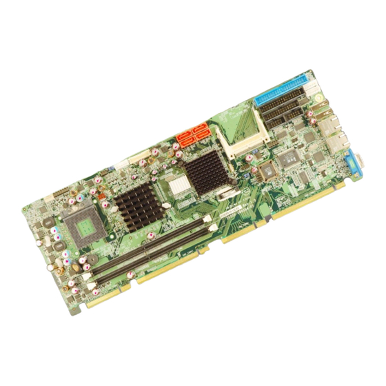
1.2.1 PCIE-9452 Overview Photo The PCIE-9452 has a wide variety of internal and external peripheral connectors. A labeled photo of the peripheral connectors on the front of the PCIE-9452 is shown in Figure 1-1. Figure 1-1: PCIE-9452 Overview [Front View] 1.2.2 PCIE-9452 Peripheral Connectors and Jumpers... -
Page 24: Technical Specifications
The PCIE-9452 has the following on-board jumpers: Clear CMOS LCD voltage selector CF card setting 1.2.3 Technical Specifications PCIE-9452 technical specifications are listed in Table 1-1. See Chapter 2 for details. Specification PCIE-9452 PICMG 1.3 Form Factor Socket 479 Intel® Core™2 Duo Socket 479 Intel®... - Page 25 PCIE-9452 PICMG 1.3 CPU Card Specification PCIE-9452 Northbridge: Intel® 945GM System Chipset Southbridge: Intel® ICH7R Two 240-pin DIMM sockets support two dual-channel Memory 400MHz, 533MHz or 667MHz DDR2 DIMMs with a maximum capacity of 2GB each ® CRT: Integrated in the Intel...
-
Page 26: Table 1-1: Technical Specifications
PCIE-9452 PICMG 1.3 CPU Card Specification PCIE-9452 Watchdog Timer Software programmable 1-255 sec. by super I/O Power Supply ATX supported 0ºC – 60ºC (32ºF - 140ºF) Temperature Humidity (operating) 5%~95% non-condensing Dimensions (LxW) 338mm x 122mm Weight (GW/NW) 1100g/ 380g... -
Page 27: Detailed Specifications
PCIE-9452 PICMG 1.3 CPU Card Chapter Detailed Specifications Page 7... -
Page 28: Overview
PCIE-9452 PICMG 1.3 CPU Card 2.1 Overview This chapter describes the specifications and on-board features of the PCIE-9452 in detail. 2.2 Dimensions 2.2.1 Board Dimensions The dimensions of the board are listed below: Length: 338mm Width: 122mm Figure 2-1: PCIE-9452 Dimensions (mm) -
Page 29: External Interface Panel Dimensions
PCIE-9452 PICMG 1.3 CPU Card 2.2.2 External Interface Panel Dimensions External peripheral interface connector panel dimensions are shown in Figure 2-2. Figure 2-2: External Interface Panel Dimensions (mm) 2.3 Data Flow Figure 2-3 shows the data flow between the two on-board chipsets and other components installed on the motherboard and described in the following sections of this chapter. -
Page 30: Figure 2-3: Data Flow Block Diagram
PCIE-9452 PICMG 1.3 CPU Card Figure 2-3: Data Flow Block Diagram Page 10... -
Page 31: Compatible Processors
PCIE-9452 PICMG 1.3 CPU Card 2.4 Compatible Processors 2.4.1 Compatible Processor Overview The PCIE-9452 supports the following socket 479 processors: Intel® Core™2 Duo Mobile processors Intel® Core™ Duo processors Intel® Core™ Solo processors Intel® Celeron® M processors ® All three of the above processors communicate with the Intel 945GM northbridge chipset through a 667MHz front side bus (FSB). -
Page 32: Intel ® 945Gm Northbridge Chipset
PCIE-9452 PICMG 1.3 CPU Card Family CPU Speed Processor # Bus Speed Mfg Tech Stepping Cache Size 2 GHz T7200 667 MHz 65 nm 4 MB 1.83 GHz T5600 667 MHz 65 nm 2 MB 1.66 GHz T5500 667 MHz... -
Page 33: Intel ® 945Gm Memory Support
® 2.5.2 Intel 945GM Memory Support WARNING: Only DDR2 memory module can be installed on the PCIE-9452. Do not install DDR memory modules. If a DDR memory module is installed on the PCIE-9452, the PCIE-9452 may be irreparably damaged. ®... -
Page 34: Intel ® 945Gm Pcie X16
PCIE-9452 PICMG 1.3 CPU Card ® 2.5.3 Intel 945GM PCIe x16 2.5.3.1 PCIe x16 Bus Overview The Intel® 945GM northbridge chipset has a dedicated 16-lane PCIe port for an external PCIe x16 graphics card. The PCIe x16 graphics card is installed on a compatible PICMG 1.3 backplane and interfaced to the northbridge through the two golden fingers shown in... -
Page 35: Intel ® 945Gm Integrated Graphics
PCIE-9452 PICMG 1.3 CPU Card PCIe power management support L0, L1, L2/L3 ready, L3 Hierarchical PCI compliant configuration mechanism for downstream components PCIe extended configuration space PCIe enhanced addressing mechanism Supports traditional PCI traffic Supports traditional AGP traffic APIC and MSI messaging support ®... -
Page 36: Intel 945Gm Tv Out Support
PCIE-9452 PICMG 1.3 CPU Card ® 2.5.4.3 Intel 945GM TV Out Support A 6-pin TV output connector is interfaced to the Intel® 945GM graphics engine. The Intel® 945GM internal graphics engine has the following TV output features: Three integrated 10-bit DACs... -
Page 37: Intel ® Ich7R Southbridge Chipset
Integrated SATA host controller with DMA operations interfaced to four SATA connectors on the PCIE-9452 Integrated IDE controller supports Ultra ATA 100/66/33 Supports the four USB 2.0 devices on the PCIE-9452 with four UHCI controllers and one EHCI controller Complies with System Management Bus (SMBus) Specification, Version 2.0 Supports Audio Codec ’97 (AC’97) Revision 2.3... -
Page 38: Intel ® Ich7R Ide Interface
PCIE-9452 PICMG 1.3 CPU Card Front left Front right Back left Back right Center Subwoofer ® 2.6.3 Intel ICH7R IDE Interface The integrated IDE interface on the ICH7R southbridge supports two IDE hard disks and ATAPI devices. PIO IDE transfers up to 16MB/s and Ultra ATA transfers of 100MB/s. The... -
Page 39: Intel ® Ich7R Low Pin Count (Lpc) Interface
® 2.6.7 Intel ICH7R SATA Controller The integrated SATA controller on the ICH7R southbridge supports four SATA drives on the PCIE-9452 with independent DMA operations. SATA controller specifications are listed below. Supports four SATA drives Supports 3Gb/s data transfer speeds... -
Page 40: Intel ® Ich7R Usb Controller
Up to eight high-speed, full-speed or low-speed USB devices are supported by the ICH7R on the PCIE-9452. High-speed USB 2.0, with data transfers of up to 480MB/s, is enabled with the ICH7R integrated Enhanced Host Controller Interface (EHCI) compliant host controller. -
Page 41: Intel ® Ich7R Pcie Bus
Four PCIe x1 expansion cards or one PCIe x4 expansion card can be installed onto a compatible PICMG 1.3 backplane and are interfaced through the PCIe x4 golden finger on the bottom of the PCIE-9452 to the southbridge chipset. The PCIe x4 golden finger is shown in Figure 2-8 below. -
Page 42: Pcie Gbe Ethernet
PCIE-9452 PICMG 1.3 CPU Card Figure 2-8: PCIe x4 Golden finger 2.6.9.3 PCIe GbE Ethernet Two PCIe x1 lanes are connected to two Broadcom BCM5787M PCIe GbE controllers shown in Figure 2-9 below. Figure 2-9: Broadcom PCI GbE Controllers The Broadcom BCM5787M is a 10/100/1000BASE-T Ethernet LAN controller. The BCM5787M combines a triple-speed IEEE 802.3 compliant Media Access Controller... -
Page 43: Lpc Bus Components
PCIE-9452 PICMG 1.3 CPU Card Wake on LAN support meeting the ACPI requirements Statistics for SNMP MIB II, Ethernet-like MIB, and Ethernet MIB (802.3z, clause 30) Serial EEPROM or serial flash support JTAG support 2.7 LPC Bus Components 2.7.1 LPC Bus Overview... -
Page 44: Super I/O Chipset
PCIE-9452 PICMG 1.3 CPU Card Figure 2-10: BIOS Chipset 2.7.3 Super I/O chipset The iTE IT8712F Super I/O chipset is connected to the ICH7 southbridge through the LPC bus. The iTE IT8712F is an LPC interface-based Super I/O device that comes with Environment Controller integration. -
Page 45: Super I/O Lpc Interface
PCIE-9452 PICMG 1.3 CPU Card Keyboard Controller Watchdog Timer Serial IRQ Support Vbat & Vcch Support Single +5V Power Supply Some of the Super I/O features are described in more detail below: 2.7.3.1 Super I/O LPC Interface The LPC interface on the Super I/O complies with the Intel® Low Pin Count Specification Rev. -
Page 46: Super I/O Parallel Port
2.8.1 System Monitoring Three thermal inputs on the PCIE-9452 Super I/O Enhanced Hardware Monitor monitor the following temperatures: System temperature Power temperature CPU temperature Eight voltage inputs on the PCIE-9452 Super I/O Enhanced Hardware Monitor monitor the following voltages: Page 26... -
Page 47: Operating Temperature And Temperature Control
The PCIE-9452 Super I/O Enhanced Hardware Monitor also monitors the following voltages internally: VBAT The PCIE-9452 Super I/O Enhanced Hardware Monitor also monitors the following fan speeds: CPU Fan speed The values for the above environmental parameters are all recorded in the BIOS Hardware Health Configuration menu. -
Page 48: Power Consumption
These backplanes and chassis are listed below. 2.9.2 IEI Expansion PICMG 1.3 Backplanes The backplanes listed in Table 2-5 are compatible with the PCIE-9452 and can be used to develop highly integrated industrial applications. All of the backplanes listed below have 24-pin ATX connector and a 4-pin ATX connector. -
Page 49: Iei Chassis
Table 2-5: Compatible IEI PICMG 1.3 Backplanes 2.9.3 IEI Chassis IEI chassis available for PCIE-9452 system development are listed in Table 2-6. For more information about these chassis please consult the IEI catalog or contact your vendor, reseller or the IEI sales team at sales@iei.com.tw. - Page 50 PCIE-9452 PICMG 1.3 CPU Card Model Slot SBC Mounting Max Slots Backplanes PAC-42GF-R20 Full-size Wall PE-4S PE-4S2 PE-4S3 PACO-504F Full-size Wall PE-4S PE-4S2 PE-4S3 PAC-106G-R20 Full-size Wall PE-5S PE-5S2 PE-6S2 PE-6S3 PAC-107G-R20 Full-size Wall PE-5S PE-5S2 PE-6S2 PE-6S3 RACK-500G-R20 Full-size (4U)
-
Page 51: Table 2-6: Compatible Iei Chassis
PCIE-9452 PICMG 1.3 CPU Card Model Slot SBC Mounting Max Slots Backplanes RACK-3000G-R20 Full-size (4U) Rack PE-6S-R20 PE-10S-R20 PE-10S2 PE-13SD PXE-13S PXE-19S PAC-1700G-R20 Full-size Wall PE-6S-R20 PE-7S PE-7S2 PAC-125G-R20 Full-size Wall PE-6S-R20 PE-8S PAC-1000G-R20 Full-size Wall PE-6S2 PE-6S3 PACO-506F Full-size... - Page 52 PCIE-9452 PICMG 1.3 CPU Card THIS PAGE IS INTENTIONALLY LEFT BLANK Page 32...
-
Page 53: Unpacking
PCIE-9452 PICMG 1.3 CPU Card Chapter Unpacking Page 33... -
Page 54: Anti-Static Precautions
When the PCIE-9452 is unpacked, please do the following: Follow the anti-static precautions outlined in Section 3.1. Make sure the packing box is facing upwards so the PCIE-9452 does not fall out of the box. Make sure all the components shown in Section 3.3 are present. -
Page 55: Unpacking Checklist
If some of the components listed in the checklist below are missing, please do not proceed with the installation. Contact the IEI reseller or vendor you purchased the PCIE-9452 from or contact an IEI sales representative directly. To contact an IEI sales representative, please send an email to sales@iei.com.tw. -
Page 56: Table 3-1: Package List Contents
PCIE-9452 PICMG 1.3 CPU Card Dual USB cable (w bracket) (P/N:CB-USB02-RS) Mini jumper pack Quick installation guide Utility CD Table 3-1: Package List Contents Page 36... -
Page 57: Optional Items
The items listed in this section are optional items that must be ordered separately. Please contact your PCIE-9452 vendor, distributor or reseller for more information or, contact iEi directly by sending an email to sales@iei.com.tw. The following optional items are available for the PCIE-9452. Quantity Item and Part Number Image Audio kit_ 5.1 Channel... -
Page 58: Table 3-2: Optional Items
PCIE-9452 PICMG 1.3 CPU Card Quantity Item and Part Number Image LPT cable (P/N:19800-000049-RS) FDD cable (P/N:32200-000017-RS) Table 3-2: Optional Items Page 38... -
Page 59: Connector Pinouts
PCIE-9452 PICMG 1.3 CPU Card Chapter Connector Pinouts Page 39... -
Page 60: Peripheral Interface Connectors
PCIE-9452 PICMG 1.3 CPU Card 4.1 Peripheral Interface Connectors Section 4.1.2 shows peripheral interface connector locations. Section 4.1.2 lists all the peripheral interface connectors seen in Section 4.1.2. 4.1.1 PCIE-9452 Layout Figure 4-1 shows the on-board peripheral connectors, rear panel peripheral connectors and on-board jumpers. -
Page 61: Peripheral Interface Connectors
PCIE-9452 PICMG 1.3 CPU Card 4.1.2 Peripheral Interface Connectors Table 4-1 shows a list of the peripheral interface connectors on the PCIE-9452. Detailed descriptions of these connectors can be found below. Connector Type Label +12V ATX power supply connector 4-pin ATX connector... -
Page 62: External Interface Panel Connectors
8-pin header USB01 Table 4-1: Peripheral Interface Connectors 4.1.3 External Interface Panel Connectors Table 4-2 lists the rear panel connectors on the PCIE-9452. Detailed descriptions of these connectors can be found in Section 4.3 on page 70 Connector Type Label... -
Page 63: Figure 4-2: Atx Power Supply Enable Connector Location
The ATX power supply enable connector enables the PCIE-9452 to be connected to an ATX power supply. In default mode, the PCIE-9452 can only us an AT power supply. To enable an ATX power supply the AT Power Select jumper must also be configured. Please refer to Chapter 3 for more details. -
Page 64: Audio Connector (9-Pin)
PCIE-9452 PICMG 1.3 CPU Card +5V Standby Table 4-3: ATX Power Supply Enable Connector Pinouts 4.2.2 Audio Connector (9-pin) CN Label: J_AUDIO1 CN Type: 9-pin header CN Location: See Figure 4-3 CN Pinouts: See Table 4-4 An optional module can be connected to the 10-pin audio connector to provide the system with a high quality AC’97 or Azalia compatible codec that provides a complete integrated... -
Page 65: Figure 4-3: Audio Connector Pinouts (10-Pin)
PCIE-9452 PICMG 1.3 CPU Card Figure 4-3: Audio Connector Pinouts (10-pin) PIN NO. DESCRIPTION PIN NO. DESCRIPTION AC97_SYNC AC97_BITCLK AC97_SDOUT AC97_PCBEEP AC97_SDIN AC97_RST# AC97_VCC AC97_GND AC97_12V Table 4-4: Audio Connector Pinouts (10-pin) Page 45... -
Page 66: Backlight Inverter Connector
5-pin wafer (1x5) CN Location: See Figure 4-4 CN Pinouts: See Table 4-5 The backlight inverter connector provides the backlight on the LCD display connected to the PCIE-9452 with +12V of power. Figure 4-4: Panel Backlight Connector Pinout Locations Page 46... -
Page 67: Compact Flash Socket
PCIE-9452 PICMG 1.3 CPU Card PIN NO. DESCRIPTION BRIGHTNESS GROUND +12V GROUND BACKLIGHT ENABLE Table 4-5: Panel Backlight Connector Pinouts 4.2.4 Compact Flash Socket CN Label: CF1 (solder side) CN Type: 50-pin header (2x25) See Figure 4-5 CN Location: CN Pinouts:... -
Page 68: Figure 4-5: Cf Card Socket Location
PCIE-9452 PICMG 1.3 CPU Card Figure 4-5: CF Card Socket Location Page 48... -
Page 69: Table 4-6: Cf Card Socket Pinouts
PCIE-9452 PICMG 1.3 CPU Card PIN NO. DESCRIPTION PIN NO. DESCRIPTION GROUND VCC-IN CHECK1 DATA 3 DATA 11 DATA 4 DATA 12 DATA 5 DATA 13 DATA 6 DATA 14 DATA 7 DATA 15 HDC_CS0# HDC_CS1 GROUND IOR# IOW# VCC_COM... -
Page 70: Digital Input/Output (Dio) Connector
PCIE-9452 PICMG 1.3 CPU Card 4.2.5 Digital Input/Output (DIO) Connector CN Label: DIO1 10-pin header (2x5) CN Type: CN Location: See Figure 4-6 CN Pinouts: See Table 4-7 The digital input/output connector is managed through a Super I/O chip. The DIO connector pins are user programmable. -
Page 71: Fan Connector (+12V)
PCIE-9452 PICMG 1.3 CPU Card Input 3 Input 2 Input 1 Input 0 Table 4-7: DIO Connector Connector Pinouts 4.2.6 Fan Connector (+12V) CN Label: CPU_FAN1 3-pin header CN Type: CN Location: See Figure 4-7 CN Pinouts: See Table 4-8 The cooling fan connector provides a 12V, 500mA current to a system cooling fan. -
Page 72: Floppy Disk Connector (34-Pin)
PCIE-9452 PICMG 1.3 CPU Card PIN NO. DESCRIPTION Ground +12V Rotation Signal Control Table 4-8: +12V Fan Connector Pinouts 4.2.7 Floppy Disk Connector (34-pin) CN Label: FDD1 CN Type: 34-pin header (2x17) CN Location: See Figure 4-8 CN Pinouts: See Table 4-9 The floppy disk connector is connected to a floppy disk drive. -
Page 73: Front Panel Connector (14-Pin)
PCIE-9452 PICMG 1.3 CPU Card PIN NO. DESCRIPTION PIN NO. DESCRIPTION REDUCE WRITE INDEX# MOTOR ENABLE A# DRIVE SELECT B# DRIVE SELECT A# MOTOR ENABLE B# DIRECTION# STEP# WRITE DATA# WRITE GATE# TRACK 0# WRITE PROTECT# READ DATA# SIDE 1 SELECT#... -
Page 74: Figure 4-9: Front Panel Connector Pinout Locations
PCIE-9452 PICMG 1.3 CPU Card Power LED HDD LED Figure 4-9: Front Panel Connector Pinout Locations FUNCTION DESCRIPTION FUNCTION DESCRIPTION Power LED Speaker Ground Power Button PWRBTN- Speaker Reset HDD LED Reset- HDD LED- Table 4-10: Front Panel Connector Pinouts... -
Page 75: Ide Connector(40-Pin)
PCIE-9452 PICMG 1.3 CPU Card 4.2.9 IDE Connector(40-pin) CN Label: IDE1 40-pin header (2x20) CN Type: CN Location: See Figure 4-10 CN Pinouts: See Table 4-11 One 40-pin IDE device connector on the PCIE-9452 supports connectivity to two hard disk drives. Page 55... -
Page 76: Figure 4-10: Secondary Ide Device Connector Locations
PCIE-9452 PICMG 1.3 CPU Card Figure 4-10: Secondary IDE Device Connector Locations PIN NO. DESCRIPTION PIN NO. DESCRIPTION RESET# GROUND DATA 7 DATA 8 DATA 6 DATA 9 DATA 5 DATA 10 DATA 4 DATA 11 DATA 3 DATA 12... -
Page 77: Infrared Interface Connector (5-Pin)
PCIE-9452 PICMG 1.3 CPU Card HDC CS0# HDC CS1# HDD ACTIVE# GROUND Table 4-11: Secondary IDE Connector Pinouts 4.2.10 Infrared Interface Connector (5-pin) CN Label: CN Type: 5-pin header (1x5) CN Location: See Figure 4-11 CN Pinouts: See Table 4-12 The infrared interface connector supports both Serial Infrared (SIR) and Amplitude Shift Key Infrared (ASKIR) interfaces. -
Page 78: Keyboard Connector
PCIE-9452 PICMG 1.3 CPU Card PIN NO. DESCRIPTION IR-RX IR-TX Table 4-12: Infrared Connector Pinouts 4.2.11 Keyboard Connector CN Label: CN Type: 5-pin header (1x5) CN Location: See Figure 4-12 See Table 4-13 CN Pinouts: The keyboard connector can be connected to a standard PS/2 cable to add keyboard functionality to the system. -
Page 79: Lvds Lcd Connector
PCIE-9452 PICMG 1.3 CPU Card Figure 4-12: Keyboard Connector Location PIN NO. DESCRIPTION KEYBOARD CLOCK KEYBOARD DATA GROUND Table 4-13: Keyboard Connector Pinouts 4.2.12 LVDS LCD Connector LVDS1 CN Label: CN Type: 30-pin crimp (2x10) CN Location: See Figure 4-13... -
Page 80: Figure 4-13: Lvds Lcd Connector Pinout Locations
PCIE-9452 PICMG 1.3 CPU Card The 30-pin LVDS LCD connector can be connected to single channel or dual channel, 18-bit or 36-bit LVDS panel. Figure 4-13: LVDS LCD Connector Pinout Locations PIN NO. DESCRIPTION PIN NO. DESCRIPTION GROUND GROUND LVDSA_Y0+... -
Page 81: Mouse Connector
PCIE-9452 PICMG 1.3 CPU Card LVDSB_Y3+ LVDSB_Y3- GROUND GROUND VCC_LVDS VCC_LVDS VCC_LVDS VCC_LVDS Table 4-14: LVDS LCD Port Connector Pinouts 4.2.13 Mouse Connector CN Label: CN Type: 5-pin header (1x5) See Figure 4-12 CN Location: CN Pinouts: See Table 4-13 The mouse connector can be connected to a standard PS/2 cable to add keyboard and mouse functionality to the system. -
Page 82: Parallel Port Connector
PCIE-9452 PICMG 1.3 CPU Card Figure 4-14: Mouse Connector Location PIN NO. DESCRIPTION MOUSE CLOCK MOUSE DATA GROUND Table 4-15: Mouse Connector Pinouts 4.2.14 Parallel Port Connector LPT1 CN Label: CN Type: 26-pin box header CN Location: See Figure 4-15... -
Page 83: Figure 4-15: Parallel Port Connector Location
PCIE-9452 PICMG 1.3 CPU Card The 26-pin parallel port connector connects to a parallel port connector interface or some other parallel port device such as a printer. Figure 4-15: Parallel Port Connector Location PIN NO. DESCRIPTION PIN NO. DESCRIPTION STROBE#... -
Page 84: Sata Drive Connectors
PCIE-9452 PICMG 1.3 CPU Card PIN NO. DESCRIPTION PIN NO. DESCRIPTION GROUND GROUND GROUND Table 4-16: Parallel Port Connector Pinouts 4.2.15 SATA Drive Connectors CN Label: SATA1, SATA2, SATA3 and SATA4 CN Type: 7-pin SATA drive connectors CN Location: See Figure 4-16... -
Page 85: Figure 4-16: Sata Drive Connector Locations
PCIE-9452 PICMG 1.3 CPU Card Figure 4-16: SATA Drive Connector Locations PIN NO. DESCRIPTION Table 4-17: SATA Drive Connector Pinouts Page 65... -
Page 86: Serial Port Connector (Com1And Com2)
PCIE-9452 PICMG 1.3 CPU Card 4.2.16 Serial Port Connector (COM1and COM2) CN Label: COM1 and COM2 10-pin header (2x5) CN Type: CN Location: See Figure 4-17 CN Pinouts: See Table 4-18 The 10-pin serial port connector provides a second RS-232 serial communications channel. -
Page 87: Tv Out Connector
PCIE-9452 PICMG 1.3 CPU Card PIN NO. DESCRIPTION PIN NO. DESCRIPTION Data Carrier Detect (DCD) Receive Data (RXD) Transmit Data (TXD) Data Terminal Ready (DTR) Ground (GND) Data Set to Ready (DSR) Request to Send (RTS) Clear to Sent (CTS) -
Page 88: Usb Connectors (Internal)
PCIE-9452 PICMG 1.3 CPU Card Figure 4-18: TV Connector Pinout Locations S-Video Connector PIN NO. DESCRIPTION PIN NO. DESCRIPTION AGREEN_Y ARED_C RCA Connector (only video signal) ABLUE_CVBS Table 4-19: TV Port Connector Pinouts 4.2.18 USB Connectors (Internal) CN Label: USB01... -
Page 89: Figure 4-19: Usb Connector Pinout Locations
PCIE-9452 PICMG 1.3 CPU Card See Table 4-20 CN Pinouts: The 2x4 USB pin connectors each provide connectivity to two USB 1.1 or two USB 2.0 ports. Each USB connector can support two USB devices.. Additional external USB ports are found on the rear panel. The USB ports are used for I/O bus expansion. -
Page 90: External Peripheral Interface Connector Panel
PCIE-9452 PICMG 1.3 CPU Card 4.3 External Peripheral Interface Connector Panel Figure 4-20 shows the PCIE-9452 rear panel. The PCIE-9452 rear panel consists of two RJ-45 Ethernet connectors, a PS/2 keyboard connector a USB port and a VGA connector. These connectors are accessible when the PCIE-9452 is installed in a chassis. -
Page 91: Usb Connector
USB_C7 and USB_C6 CN Label: CN Type: USB port CN Location: See Figure 4-20 CN Pinouts: See Table 4-23 The PCIE-9452 has a one external USB 2.0 port. The port connects to both USB 2.0 and USB 1.1 devices. Page 71... -
Page 92: Vga Connector
CN Label: CN Type: 15-pin Female CN Location: See Figure 4-20 CN Pinouts: See Figure 4-22 and Table 4-24 The PCIE-9452 has a single 15-pin female connector for connectivity to standard display devices. Figure 4-22: VGA Connector DESCRIPTION DESCRIPTION GREEN BLUE... -
Page 93: Table 4-24: Vga Connector Pinouts
PCIE-9452 PICMG 1.3 CPU Card DESCRIPTION DESCRIPTION HSYNC VSYNC DDCCLK Table 4-24: VGA Connector Pinouts Page 73... - Page 94 PCIE-9452 PICMG 1.3 CPU Card THIS PAGE IS INTENTIONALLY LEFT BLANK Page 74...
-
Page 95: Installation
PCIE-9452 PICMG 1.3 CPU Card Chapter Installation Page 75... -
Page 96: Anti-Static Precautions
Electrostatic discharge (ESD) can cause serious damage to electronic components, including the PCIE-9452. Dry climates are especially susceptible to ESD. It is therefore critical that whenever the PCIE-9452, or any other electrical component is handled, the following anti-static precautions are strictly adhered to. -
Page 97: Installation Considerations
PCIE-9452 is installed. All installation notices pertaining to the installation of the PCIE-9452 should be strictly adhered to. Failing to adhere to these precautions may lead to severe damage of the PCIE-9452 and injury to the person installing the motherboard. 5.2.1 Installation Notices... -
Page 98: Installation Checklist
PCIE-9452 PICMG 1.3 CPU Card When working with the PCIE-9452, make sure that it is disconnected from all power supplies and that no electricity is being fed into the system. Before and during the installation of the PCIE-9452 DO NOT: Remove any of the stickers on the PCB board. -
Page 99: Cpu, Cpu Cooling Kit And Dimm Installation
Running a CPU without a cooling kit may also result in injury to the user. The CPU, CPU cooling kit and DIMM are the most critical components of the PCIE-9452. If one of these component is not installed the PCIE-9452 cannot run. -
Page 100: Figure 5-1: Make Sure The Cpu Socket Retention Screw Is Unlocked
PCIE-9452 PICMG 1.3 CPU Card WARNING: When handling the CPU, only hold it on the sides. DO NOT touch the pins at the bottom of the CPU. Step 1: Unlock the CPU retention screw. When shipped, the retention screw of the CPU socket should be in the unlocked position. -
Page 101: Figure 5-2: Lock The Cpu Socket Retention Screw
PCIE-9452 PICMG 1.3 CPU Card Step 5: Align the CPU pins. Carefully align the CPU pins with the holes in the CPU socket. Step 6: Insert the CPU. Gently insert the CPU into the socket. If the CPU pins are properly aligned, the CPU should slide into the CPU socket smoothly. -
Page 102: Cooling Kit Cf-479B-Rs Installation
PCIE-9452 PICMG 1.3 CPU Card 5.3.2 Cooling Kit CF-479B-RS Installation Figure 5-3: IEI CF-479B-RS Cooling Kit An IEI Socket 479 CPU cooling kit can be purchased separately. The cooling kit comprises a CPU heat sink and a cooling fan. WARNING: Do not wipe off (accidentally or otherwise) the pre-sprayed layer of thermal paste on the bottom of the [Fan model#] heat sink. -
Page 103: Figure 5-4: Cooling Kit Support Bracket
PCIE-9452 PICMG 1.3 CPU Card Figure 5-4: Cooling Kit Support Bracket Step 4: Tighten the screws. Use a screwdriver to tighten the four screws. Tighten each nut a few turns at a time and do not over-tighten the screws. Step 5: Connect the fan cable. -
Page 104: Dimm Installation
5.3.3 DIMM Installation WARNING: Using incorrectly specified DIMM may cause permanently damage the PCIE-9452. Please make sure the purchased DIMM complies with the memory specifications of the PCIE-9452. DIMM specifications compliant with the PCIE-9452 are listed in Chapter 2. To install a DIMM into a DIMM socket, please follow the steps below and refer to Figure 5-6. -
Page 105: Cf Card Installation
The PCIE-9452 can support both CF Type I cards and CF Type II cards. For the complete specifications of the supported CF cards please refer to Chapter 2. To install the a CF card (Type 1 or Type 2) onto the PCIE-9452, please follow the steps below: Step 1: Locate the CF card socket. -
Page 106: Figure 5-7: Cf Card Installation
PCIE-9452 PICMG 1.3 CPU Card Figure 5-7: CF Card Installation Page 86... -
Page 107: Jumper Settings
OPEN a jumper means removing the Figure 5-8: Jumper Locations plastic clip from a jumper. Before the PCIE-9452 is installed in the system, the jumpers must be set in accordance with the desired configuration. The jumpers on the PCIE-9452 are listed in Table 5-1. Description... -
Page 108: Cf Card Setup
PCIE-9452 PICMG 1.3 CPU Card 5.4.1 CF Card Setup Jumper Label: J_CF1 3-pin header Jumper Type: Jumper Settings: See Table 5-2 Jumper Location: See Figure 5-9 The CF Card Setup jumper sets the CF Type I card or CF Type II cards as either the slave device or the master device. -
Page 109: Clear Cmos Jumper
Jumper Location: See Figure 5-10 If the PCIE-9452 fails to boot due to improper BIOS settings, the clear CMOS jumper clears the CMOS data and resets the system BIOS information. To do this, use the jumper cap to close pins 2 and 3 for a few seconds then reinstall the jumper clip back to pins 1 and 2. -
Page 110: Figure 5-10: Clear Cmos Jumper
PCIE-9452 PICMG 1.3 CPU Card Enter the correct CMOS setting Load Optimal Defaults Load Failsafe Defaults. After having done one of the above, save the changes and exit the CMOS Setup menu. The clear CMOS jumper settings are shown in Table 5-3. -
Page 111: Lvds Voltage Selection
PCIE-9452 PICMG 1.3 CPU Card 5.4.3 LVDS Voltage Selection WARNING: Permanent damage to the screen and PCIE-9452 may occur if the wrong voltage is selected with this jumper. Please refer to the user guide that cam with the monitor to select the correct voltage. -
Page 112: Chassis Installation
The PCIE-9452 must be installed in a chassis with ventilation holes on the sides allowing airflow to travel through the heat sink surface. In a system with an individual power supply unit, the cooling fan of a power supply can also help generate airflow through the board surface. -
Page 113: Backplane Installation
5.5.2 Backplane Installation Before the PCIE-9452 can be installed into the chassis, a backplane must first be installed. Please refer to the installation instructions that came with the backplane and the chassis to see how to install the backplane into the chassis. -
Page 114: Internal Peripheral Device Connections
7.1 channel audio kit 5.1 channel audio kit 5.6.2 IDE Cable Connection The IDE flat cable connects to the PCIE-9452 to one or two IDE devices. To connect an IDE HDD to the PCIE-9452 please follow the instructions below. Step 1: Locate the IDE connector. -
Page 115: Channel Audio Kit Installation
5.6.3 5.1 Channel Audio Kit Installation NOTE: This is an optional item that must be ordered separately. For further information please contact the nearest PCIE-9452 distributor, reseller or vendor or contact an iEi sales representative directly. Send any queries to sales@iei.com.tw. -
Page 116: Figure 5-13: 5.1 Channel Audio Kit
The optional 5.1 channel audio kit connects to the 10-pin audio connector on the PCIE-9452. The audio kit consists of three audio jacks. One audio jack, Mic In, connects to a microphone. The remaining two audio jacks, Line-In and Line-Out, connect to two speakers. -
Page 117: Channel Audio Kit Installation
The optional 7.1 channel audio kit connects to the 10-pin audio connector on the PCIE-9452. The audio kit consists of five audio jacks. One audio jack, Mic In, connects to a microphone. The remaining four audio jacks, Line-In, Front-Out, Rear-Out, and Center Subwoofer, connect to speakers. -
Page 118: Parallel Port Cable
Step 4: Mount the audio kit onto the chassis. Once the audio kit is connected to the PCIE-9452, secure the audio kit bracket to the system chassis. Step 5: Connect the audio devices. Connect one speaker to the line-in audio jack, one speaker to the line-out audio jack and a microphone to the mic-in audio jack. -
Page 119: Figure 5-15: Lpt Cable Connection
Step 3: Insert the cable connectors. Once the cable connector is properly aligned with the 26-pin box-header connector on the PCIE-9452, connect the cable connector to the onboard connector. See Figure 5-15. Figure 5-15: LPT Cable Connection Step 4: Attach the LPT connector bracket to the chassis. The LPT cable connector is connected to a standard external LPT interface connector. -
Page 120: Dual Rs-232 Cable Connection
PCIE-9452 PICMG 1.3 CPU Card Figure 5-16: Connect the LPT Device 5.6.6 Dual RS-232 Cable Connection The dual RS-232 cable consists of two connectors attached to two independent cables. Each cable is then attached to a D-sub 9 male connector that is mounted onto a bracket. -
Page 121: Usb Cable (Dual Port)
0: 5.6.7 USB Cable (Dual Port) The PCIE-9452 is shipped with a dual port USB 2.0 cable. To connect the USB cable connector, please follow the steps below. Step 1: Locate the connectors. -
Page 122: Sata Drive Connection
0: 5.6.8 SATA Drive Connection The PCIE-9452 is shipped with two SATA drive cables and one SATA drive power cable. To connect the SATA drives to the connectors, please follow the steps below. Step 1: Locate the connectors. -
Page 123: Figure 5-19: Sata Drive Cable Connection
PCIE-9452 PICMG 1.3 CPU Card Figure 5-19: SATA Drive Cable Connection Step 3: Connect the cable to the SATA disk. Connect the connector on the other end of the cable to the connector at the back of the SATA drive. See Figure 5-20. -
Page 124: Wafer-To-Ps/2 Cable (Keyboard/Mouse Installation)
PCIE-9452 keyboard or mouse connector. See Figure 5-21. Step 3: Insert the cable connectors. Once the cable connector is properly aligned with the keyboard/mouse connector on the PCIE-9452, connect the cable connector to the onboard connectors. See Figure 5-21. Page 104... -
Page 125: External Peripheral Interface Connection
PCIE-9452 PICMG 1.3 CPU Card Figure 5-21: Keyboard/mouse Cable Connection Step 4: Attach PS/2 connector to the chassis. The wafer-to-PS/2 cable connector is connected to a PS/2 connector. To secure the PS/2 connector to the chassis please refer to the installation instructions that came with the chassis. -
Page 126: Lan Connection (Single Connector)
PCIE-9452 PICMG 1.3 CPU Card To install these devices, connect the corresponding cable connector from the actual device to the corresponding PCIE-9452 external peripheral interface connector making sure the pins are properly aligned. 5.7.1 LAN Connection (Single Connector) There are two external RJ-45 LAN connectors. The RJ-45 connectors enable connection to an external network. -
Page 127: Usb Device Connection (Single Connector)
PCIE-9452 PICMG 1.3 CPU Card 5.7.2 USB Device Connection (Single Connector) There are two external USB 2.0 connectors. Both connectors are perpendicular to the PCIE-9452. To connect a USB 2.0 or USB 1.1 device, please follow the instructions below. Step 1: Located the USB connectors. -
Page 128: Vga Monitor Connection
PCIE-9452 PICMG 1.3 CPU Card 5.7.3 VGA Monitor Connection The PCIE-9452 has a single female DB-15 connector on the external peripheral interface panel. The DB-15 connector is connected to a CRT or VGA monitor. To connect a monitor to the PCIE-9452, please follow the instructions below. -
Page 129: Ami Bios
PCIE-9452 PICMG 1.3 CPU Card Chapter AMI BIOS Page 109... -
Page 130: Introduction
PCIE-9452 PICMG 1.3 CPU Card 6.1 Introduction A licensed copy of AMI BIOS is preprogrammed into the ROM BIOS. The BIOS setup program allows users to modify the basic system configuration. This chapter describes how to access the BIOS setup program and the configuration options that may be changed. -
Page 131: Getting Help
PCIE-9452 PICMG 1.3 CPU Card Function F1 key General help, only for Status Page Setup Menu and Option Page Setup Menu F2 /F3 key Change color from total 16 colors. F2 to select color forward. F10 key Save all the CMOS changes, only for Main Menu Table 6-1: BIOS Navigation Keys 6.1.3 Getting Help... -
Page 132: Main
PCIE-9452 PICMG 1.3 CPU Card 6.2 Main The Main BIOS menu (BIOS Menu 1) appears when the BIOS Setup program is entered. The Main menu gives an overview of the basic system information. BIOS Menu 1: Main System Overview The System Overview lists a brief summary of different system components. The fields in System Overview cannot be changed. -
Page 133: Advanced
PCIE-9452 PICMG 1.3 CPU Card Processor: Displays auto-detected CPU specifications Type: Names the currently installed processor Speed: Lists the processor speed Count: The number of CPUs on the motherboard System Memory: Displays the auto-detected system memory. Size: Lists memory size... -
Page 134: Cpu Configuration
PCIE-9452 PICMG 1.3 CPU Card ACPI Configuration (see Section 6.3.6) APM Configuration (See Section 6.3.6) MPS Configuration (see Section 6.3.7) Remote Access Configuration (see Section 0) USB Configuration (see Section 0) BIOS Menu 2: Advanced 6.3.1 CPU Configuration Use the CPU Configuration menu (BIOS Menu 3) to view detailed CPU specifications and configure the CPU. -
Page 135: Menu 3: Cpu Configuration
PCIE-9452 PICMG 1.3 CPU Card BIOS Menu 3: CPU Configuration The CPU Configuration menu (BIOS Menu 3) lists the following CPU details: Manufacturer: Lists the name of the CPU manufacturer Brand String: Lists the brand name of the CPU being used... -
Page 136: Ide Configuration
PCIE-9452 PICMG 1.3 CPU Card 6.3.2 IDE Configuration Use the IDE Configuration menu (BIOS Menu 4) to change and/or set the configuration of the IDE devices installed in the system. BIOS Menu 4: IDE Configuration ATA/IDE Configurations [Compatible] Disabled (Default) -
Page 137: Ide Master, Ide Slave
PCIE-9452 PICMG 1.3 CPU Card Legacy IDE Channels [PATA Pri, SATA Sec] SATA Only PATA Pri, SATA Sec SATA Pri., PATA Sec (Default) PATA Only IDE Master and IDE Slave When entering setup, BIOS auto detects the presence of IDE devices. BIOS displays the status of the auto detected IDE devices. -
Page 138: Menu 5: Ide Master And Ide Slave Configuration
PCIE-9452 PICMG 1.3 CPU Card BIOS Menu 5: IDE Master and IDE Slave Configuration Auto-Detected Drive Parameters The “grayed-out” items in the left frame are IDE disk drive parameters automatically detected from the firmware of the selected IDE disk drive. The drive parameters are listed as follows: Device: Lists the device type (e.g. - Page 139 PCIE-9452 PICMG 1.3 CPU Card interrupt if block mode is not used. Block mode allows transfers of up to 64 KB per interrupt. PIO Mode: Indicates the PIO mode of the installed device. Async DMA: Indicates the highest Asynchronous DMA Mode that is supported.
- Page 140 PCIE-9452 PICMG 1.3 CPU Card LBA/Large Mode [Auto] Use the LBA/Large Mode option to disable or enable BIOS to auto detects LBA (Logical Block Addressing). LBA is a method of addressing data on a disk drive. In LBA mode, the maximum drive capacity is 137 GB.
- Page 141 PCIE-9452 PICMG 1.3 CPU Card PIO mode 0 selected with a maximum transfer rate of 3.3MBps PIO mode 1 selected with a maximum transfer rate of 5.2MBps PIO mode 2 selected with a maximum transfer rate of 8.3MBps PIO mode 3 selected with a maximum transfer rate of 11.1MBps PIO mode 4 selected with a maximum transfer rate of 16.6MBps...
- Page 142 PCIE-9452 PICMG 1.3 CPU Card UDMA1 Ultra DMA mode 0 selected with a maximum data transfer rate of 16.6MBps Ultra DMA mode 1 selected with a maximum data transfer UDMA1 rate of 25MBps UDMA2 Ultra DMA mode 2 selected with a maximum data transfer rate of 33.3MBps...
-
Page 143: Floppy Configuration
PCIE-9452 PICMG 1.3 CPU Card Disabled Prevents the BIOS from using 32-bit data transfers. Enabled Allows BIOS to use 32-bit data transfers on supported EFAULT hard disk drives. 6.3.3 Floppy Configuration Use the Floppy Configuration menu to configure the floppy disk drive connected to the system. -
Page 144: Super Io Configuration
PCIE-9452 PICMG 1.3 CPU Card Disabled 360 KB 51/4” 1.2 MB 51/4” 720 KB 31/2” 1.44 MB 31/2’ D EFAULT 2.88 MB 31/2” 6.3.4 Super IO Configuration Use the Super IO Configuration menu (BIOS Menu 7) to set or change the configurations for the FDD controllers, parallel ports and serial ports. - Page 145 PCIE-9452 PICMG 1.3 CPU Card Serial Port1 Address [3F8/IRQ4] Use the Serial Port1 Address option to select the Serial Port 1 base address. Disabled No base address is assigned to Serial Port 1 3F8/IRQ4 Serial Port 1 I/O port address is 3F8 and the interrupt...
- Page 146 PCIE-9452 PICMG 1.3 CPU Card address is IRQ3 Serial Port2 Mode [Normal] Use the Serial Port2 Mode option to select the Serial Port2 operational mode. Normal Serial Port 2 mode is normal EFAULT IrDA Serial Port 2 mode is IrDA...
-
Page 147: Hardware Health Configuration
PCIE-9452 PICMG 1.3 CPU Card The parallel port operates in the extended capabilities port (ECP) mode. The ECP mode supports bi-directional communication between the system and the parallel port device and the transmission rates between the two are much faster... -
Page 148: Menu 8: Hardware Health Configuration
PCIE-9452 PICMG 1.3 CPU Card BIOS Menu 8: Hardware Health Configuration CPU FAN Mode Setting [Full On Mode] Use the CPU FAN Mode Setting option to configure the second fan. Full On Mode Fan is on all the time EFAULT... - Page 149 PCIE-9452 PICMG 1.3 CPU Card CPU Temp. Limit of OFF CPU Temp. Limit of Start CPU Temp. Limit of Full CPU Fan Start PWM Slope PWM 1 When the CPU FAN Mode Setting option is in the PWM Manual Mode, the following parameters can be set.
- Page 150 PCIE-9452 PICMG 1.3 CPU Card CPU Temp. Limit of Start [020] WARNING: Setting this value too high may cause the fan to start only when the CPU is at a high temperature and therefore cause the system to be damaged.
- Page 151 PCIE-9452 PICMG 1.3 CPU Card speed. To select a value, select the CPU Temp. Limit of Full option and enter a decimal number between 000 and 127. The temperature range is specified below. Minimum Value: 0°C Maximum Value: 127°C CPU Fan Start PWM [070] The Fan 3 Start PWM option can only be set if the CPU FAN Mode Setting option is set to Automatic Mode.
- Page 152 PCIE-9452 PICMG 1.3 CPU Card CPU Fan PWM Control [070] The CPU Fan PWM Control option can only be set if the CPU FAN Mode Setting option is set to Manual Mode. Use the CPU Fan PWM Control option to select PWM duty cycle control.
-
Page 153: Acpi Configuration
PCIE-9452 PICMG 1.3 CPU Card 6.3.6 ACPI Configuration The ACPI Configuration menu (BIOS Menu 9) configures the Advanced Configuration and Power Interface (ACPI) and Power Management (APM) options. BIOS Menu 9: ACPI Configuration ACPI Aware O/S [Yes] Use the ACPI Aware O/S option to enable the system to configure ACPI power saving options. -
Page 154: General Acpi Configuration
PCIE-9452 PICMG 1.3 CPU Card Enables the ACPI support for the operating system. This EFAULT selection should be enabled if the OS does support ACPI 6.3.6.1 General ACPI Configuration Use the General ACPI Configuration menu (BIOS Menu 10) to select the ACPI state when the system is suspended. -
Page 155: Apm Configuration
PCIE-9452 PICMG 1.3 CPU Card S1 (POS) The system enters S1(POS) sleep state. The system EFAULT appears off. The CPU is stopped; RAM is refreshed; the system is running in a low power mode. S3 (STR) The system enters a S3(STR) sleep state. The CPU has no power;... -
Page 156: Menu 11:Advanced Power Management Configuration
PCIE-9452 PICMG 1.3 CPU Card BIOS Menu 11:Advanced Power Management Configuration Power Management/APM [Enabled] Use the Power Management/APM BIOS option to enable access to the advanced power management features. If this option is disabled, the only other option on the screen is the Power Button Mode. - Page 157 PCIE-9452 PICMG 1.3 CPU Card Restore on AC Power Loss [Power Off] Use the Restore on AC Power Loss BIOS option to specify what state the system returns to if there is a sudden loss of power to the system.
- Page 158 PCIE-9452 PICMG 1.3 CPU Card Disabled (Default) Wake event not generated by PCI PME controller activity Wake event generated by PCI PME controller activity Enabled Resume On RTC Alarm [Disabled] Use the Resume On RTC Alarm option to specify the time the system should be roused from a suspended state.
-
Page 159: Mps Configuration
PCIE-9452 PICMG 1.3 CPU Card 6.3.8 MPS Configuration Use the MPS Configuration menu (BIOS Menu 12) to select `he multi-processor table. BIOS Menu 12: MPS Configuration MPS Revision [1.4] Use the Multiprocessor Specification (MPS) for OS option to specify the MPS version to be used. -
Page 160: Remote Access Configuration
PCIE-9452 PICMG 1.3 CPU Card 6.3.9 Remote Access Configuration Use the Remote Access Configuration menu (BIOS Menu 13) to configure remote access parameters. The Remote Access Configuration is an AMIBIOS feature and allows a remote host running a terminal program to display and configure the BIOS settings. - Page 161 PCIE-9452 PICMG 1.3 CPU Card Enabled Remote access configuration options shown below appear: Serial Port Number Serial Port Mode Flow Control Redirection after BIOS POST Terminal Type VT-UTF8 Combo Key Support These configuration options are discussed below. Serial Port Number [COM1] Use the Serial Port Number option allows to select the serial port used for remote access.
- Page 162 PCIE-9452 PICMG 1.3 CPU Card 115200 8,n,1 D EFAULT 57600 8,n,1 38400 8,n,1 19200 8,n,1 09600 8,n,1 NOTE: Identical baud rate setting musts be set on the host (a management computer running a terminal software) and the slave Flow Control [None] Use the Flow Control option to report the flow control method for the console redirection application.
- Page 163 PCIE-9452 PICMG 1.3 CPU Card Terminal Type [ANSI] Use the Terminal Type BIOS option to specify the remote terminal type. ANSI The target terminal type is ANSI EFAULT VT100 The target terminal type is VT100 VT-UTF8 The target terminal type is VT-UTF8...
-
Page 164: Usb Configuration
PCIE-9452 PICMG 1.3 CPU Card 6.3.10 USB Configuration Use the USB Configuration menu (BIOS Menu 14) to read USB configuration information and configure the USB settings. BIOS Menu 14: USB Configuration USB Function [8 USB ports] Use the USB Function BIOS option to enable or disable a specified number of USB ports. - Page 165 PCIE-9452 PICMG 1.3 CPU Card Disabled USB function support disabled 2 USB Ports Two USB ports are enabled 4 USB Ports Four USB ports are enabled 6 USB Ports Six USB ports are enabled Eight USB ports are enabled 8 USB Ports EFAULT USB 2.0 Controller [Enabled]...
-
Page 166: Pci/Pnp
PCIE-9452 PICMG 1.3 CPU Card FullSpeed The controller is capable of operating at 12Mb/s HiSpeed The controller is capable of operating at 480Mb/s EFAULT 6.4 PCI/PnP Use the PCI/PnP menu (BIOS Menu 14) to configure advanced PCI and PnP settings. -
Page 167: Menu 15: Pci/Pnp Configuration
PCIE-9452 PICMG 1.3 CPU Card BIOS Menu 15: PCI/PnP Configuration Clear NVRAM [No] Use the Clear NVRAM option to specify if the NVRAM (Non-Volatile RAM) is cleared when the power is turned off. System does not clear NVRAM during system boot... - Page 168 PCIE-9452 PICMG 1.3 CPU Card If the operating system does not meet the Plug and Play EFAULT specifications, this option allows the BIOS to configure all the devices in the system. This setting allows the operating system to change the interrupt, I/O, and DMA settings.
- Page 169 PCIE-9452 PICMG 1.3 CPU Card Disabled Unless the VGA card manufacturer requires palette EFAULT snooping to be enabled, this option should be disabled. PCI devices are informed that an ISA based Graphics Enabled device is installed in the system so the ISA based Graphics card functions correctly.
- Page 170 PCIE-9452 PICMG 1.3 CPU Card adapter card is installed in PCI Slot 2. PCI Slot 3 PCI Slot 3 is selected as the location of the OffBoard PCI IDE adapter card. Only select this slot if the adapter card is installed in PCI Slot 3.
- Page 171 PCIE-9452 PICMG 1.3 CPU Card IRQ10 IRQ 11 IRQ 14 IRQ 15 DMA Channel# [Available] Use the DMA Channel# option to assign a specific DMA channel to a particular PCI/PnP device. Available The specified DMA is available to be used by...
-
Page 172: Boot
PCIE-9452 PICMG 1.3 CPU Card 6.5 Boot Use the Boot menu (BIOS Menu 16) to configure system boot options. BIOS Menu 16: Boot 6.5.1 Boot Settings Configuration Use the Boot Settings Configuration menu (BIOS Menu 16) to configure advanced system boot options. -
Page 173: Menu 17: Boot Settings Configuration
PCIE-9452 PICMG 1.3 CPU Card BIOS Menu 17: Boot Settings Configuration Quick Boot [Enabled] Use the Quick Boot BIOS option to make the computer speed up the boot process. Disabled No POST procedures are skipped Enabled Some POST procedures are skipped to decrease... - Page 174 PCIE-9452 PICMG 1.3 CPU Card Enabled OEM Logo displayed instead of POST messages AddOn ROM Display Mode [Force BIOS] Use the AddOn ROM Display Mode option to allow add-on ROM (read-only memory) messages to be displayed. The system forces third party BIOS to display...
-
Page 175: Boot Device Priority
PCIE-9452 PICMG 1.3 CPU Card Disabled PS/2 mouse support is disabled and prevented from using system resources. Allows the system to use a PS/2 mouse. Enabled EFAULT Auto The system auto-adjusts PS/2 mouse support. Giga LAN Boot Support [Disabled] Use the Giga LAN Boot Support option to enable the system to be booted from a remote system. -
Page 176: Menu 18: Boot Device Priority Settings
PCIE-9452 PICMG 1.3 CPU Card BIOS Menu 18: Boot Device Priority Settings Page 156... -
Page 177: Hard Disk Drives
PCIE-9452 PICMG 1.3 CPU Card 6.5.3 Hard Disk Drives Use the Hard Disk Drives menu to specify the boot sequence of the available HDDs. When the menu is opened, the HDDs connected to the system are listed as shown below:... -
Page 178: Removable Drives
PCIE-9452 PICMG 1.3 CPU Card BIOS Menu 19: Hard Disk Drives 6.5.4 Removable Drives Use the Removable Drives menu (BIOS Menu 20) to specify the boot sequence of the available FDDs. When the menu is opened, the FDDs connected to the system are listed... -
Page 179: Menu 20: Removable Drives
PCIE-9452 PICMG 1.3 CPU Card NOTE: Only the drives connected to the system are shown. For example, if only one FDD is connected only “1st Drive” is listed. The boot sequence from the available devices is selected. If the “1st Drive” option is selected a list of available FDDs is shown. -
Page 180: Cd/Dvd Drives
PCIE-9452 PICMG 1.3 CPU Card 6.5.5 CD/DVD Drives Use the CD/DVD Drives menu to specify the boot sequence of the available CD/DVD drives. When the menu is opened, the CD drives and DVD drives connected to the system are listed as shown below:... -
Page 181: Menu 21: Cd/Dvd Drives
PCIE-9452 PICMG 1.3 CPU Card BIOS Menu 21: CD/DVD Drives Page 161... -
Page 182: Security
PCIE-9452 PICMG 1.3 CPU Card 6.6 Security Use the Security menu (BIOS Menu 22) to set system and user passwords. BIOS Menu 22: Security Change Supervisor Password Use the Change Supervisor Password to set or change a supervisor password. The default for this option is Not Installed. -
Page 183: Chipset
PCIE-9452 PICMG 1.3 CPU Card Change User Password Use the Change User Password to set or change a user password. The default for this option is Not Installed. If a user password must be installed, select this field and enter the password. -
Page 184: Northbridge Configuration
PCIE-9452 PICMG 1.3 CPU Card BIOS Menu 23: Chipset 6.7.1 NorthBridge Configuration Use the NorthBridge Configuration menu (BIOS Menu 23) to configure the northbridge chipset. Page 164... -
Page 185: Menu 24:Northbridge Chipset Configuration
PCIE-9452 PICMG 1.3 CPU Card BIOS Menu 24:NorthBridge Chipset Configuration DRAM Frequency [Auto] Use the DRAM Frequency option to specify the DRAM frequency or allow the system to automatically detect the DRAM frequency. 400MHz Sets the DRAM frequency to 400MHz... - Page 186 PCIE-9452 PICMG 1.3 CPU Card Configure DRAM Timing by SPD [Enabled] Use the Configure DRAM Timing by SPD option to determine if the system uses the SPD (Serial Presence Detect) EEPROM to configure the DRAM timing. The SPD EEPROM contains all necessary DIMM specifications including the speed of the individual components such as CAS and bank cycle time as well as valid settings for the module and the manufacturer's code.
- Page 187 PCIE-9452 PICMG 1.3 CPU Card DRAM RAS# to CAS# Delay [6 DRAM Clocks] Use the DRAM RAS# to CAS# Delay option to specify the number of clock cycles must elapse between sending a RAS (row address strobe) signal and the CAS (column address strobe) signal.
- Page 188 PCIE-9452 PICMG 1.3 CPU Card that is considered when memory has hit the last column in a specific row, or when an entirely different memory location is requested. (To be able to change this configuration option the Configure DRAM Timing by SPD configuration option must be set to “Disabled”) The following configuration options are available:...
-
Page 189: Video Function Configuration
PCIE-9452 PICMG 1.3 CPU Card Boots Graphics Adapter [PEG/PCI] Use the Boots Graphics Adapter option to select the graphics controller used as the primary boot device. Select either an integrated graphics controller (IGD) or a combination of PCI graphics controller, a PCI express (PEG) controller or an IGD. Configuration... -
Page 190: Figure 6-1: Video Function Configuration
PCIE-9452 PICMG 1.3 CPU Card Figure 6-1: Video Function Configuration DVMT Mode Select [DVMT Mode] Use the DVMT Mode Select option to select the Intel Dynamic Video Memory Technology (DVMT) operating mode. Fixed Mode A fixed portion of graphics memory is reserved as graphics memory. - Page 191 PCIE-9452 PICMG 1.3 CPU Card DVMT/FIXED Memory Use the DVMT/FIXED Memory option to specify the maximum amount of memory that can be allocated as graphics memory. This option can only be configured for if DVMT Mode or Fixed Mode is selected in the DVMT Mode Select option. If Combo Mode is selected, the maximum amount of graphics memory is 128MB.
- Page 192 PCIE-9452 PICMG 1.3 CPU Card 1440*900(48bits) 1280*800(18bits) 1280*600(18bits) 2048*1536(36bits) Local Flat Panel Scaling [Auto] Use the Local Flat Panel Scaling option to select the method of scaling for the flat panel screen attached to the system. Auto Scaling is automatic...
- Page 193 PCIE-9452 PICMG 1.3 CPU Card The two scanning types can be selected interlaced (i) or progressive (p). Interlaced scanning divides and presents each video frame as two fields. The first field presents the odd lines and the second field presents the even lines. In progressive scanning, the image is refreshed from top to bottom, one line after the other.
-
Page 194: Southbridge Chipset Configuration
PCIE-9452 PICMG 1.3 CPU Card ETA-770.2 ETA-770.3 6.7.2 SouthBridge Chipset Configuration The SouthBridge Chipset Configuration menu (BIOS Menu 25) the southbridge chipset to be configured. BIOS Menu 25:SouthBridge Chipset Configuration Audio Controller [AC`97 Audio] The Audio Controller option allows selection of the audio controller to use. - Page 195 PCIE-9452 PICMG 1.3 CPU Card AC`97 Audio The on-board AC’97 controller is enabled All Disabled All audio controllers are disabled PCIE Port n [Enabled] Use the PCIE Port n option to determine enable or disable the nth PCIe port. nth PCI Express port is detected automatically...
-
Page 196: Exit
PCIE-9452 PICMG 1.3 CPU Card 6.8 Exit Use the Exit menu (BIOS Menu 26) to load default BIOS values, optimal failsafe values and to save configuration changes. BIOS Menu 26:Exit Save Changes and Exit Use the Save Changes and Exit option to save the changes made to the BIOS options and to exit the BIOS configuration setup program. - Page 197 PCIE-9452 PICMG 1.3 CPU Card Discard Changes Use the Discard Changes option to discard the changes and remain in the BIOS configuration setup program. Load Optimal Defaults Use the Load Optimal Defaults option to load the optimal default values for each of the parameters on the Setup menus.
- Page 198 PCIE-9452 PICMG 1.3 CPU Card THIS PAGE IS INTENTIONALLY LEFT BLANK Page 178...
-
Page 199: Driver Installation
PCIE-9452 PICMG 1.3 CPU Card Chapter Driver Installation Page 179... -
Page 200: Available Software Drivers
LAN driver Installation instructions are given below. 7.2 Driver CD Auto-run All the drivers for the PCIE-9452 are on the CD that came with the system. To install the drivers, please follow the steps below. Step 1: Insert the CD into a CD drive connected to the system. -
Page 201: Figure 7-1: Introduction Screen
PCIE-9452 PICMG 1.3 CPU Card Figure 7-1: Introduction Screen Step 4: A new screen with a list of available drivers appears (Figure 7-2). Page 181... -
Page 202: Chipset Driver Installation
PCIE-9452 PICMG 1.3 CPU Card Figure 7-2: Available Drivers Step 5: Select the driver to install from the list in Figure 7-2. Step 0: 7.3 Chipset Driver Installation To install the chipset driver, please follow the steps below: Step 1: Select the INF driver from the list in Figure 7-2. -
Page 203: Figure 7-3: Chipset Driver Installation Program
PCIE-9452 PICMG 1.3 CPU Card Figure 7-3: Chipset Driver Installation Program Step 3: Double click the infinst_Autol icon in Figure 7-3. Step 4: The welcome screen in Figure 7-4 appears. Page 183... -
Page 204: Figure 7-4: Chipset Driver Installation Welcome Screen
PCIE-9452 PICMG 1.3 CPU Card Figure 7-4: Chipset Driver Installation Welcome Screen Step 5: Click N in Figure 7-4 to continue the installation process. Step 6: The license agreement in Figure 7-5 appears. Page 184... -
Page 205: Figure 7-5: Chipset Driver Installation License Agreement
PCIE-9452 PICMG 1.3 CPU Card Figure 7-5: Chipset Driver Installation License Agreement Step 7: Click Y to continue the setup. Step 8: The Readme file in Figure 7-6 appears. Page 185... -
Page 206: Figure 7-6: Chipset Driver Readme File Information
PCIE-9452 PICMG 1.3 CPU Card Figure 7-6: Chipset Driver Readme File Information Step 9: Click N in Figure 7-6 to start the driver installation. Step 10: After the driver installation process is complete, a confirmation screen (Figure 7-7) appears. Step 0:... -
Page 207: Intel Graphics Media Accelerator Driver
PCIE-9452 PICMG 1.3 CPU Card Figure 7-7: Chipset Driver Installation Complete 7.4 Intel Graphics Media Accelerator Driver To install the chipset driver, please follow the steps below: Step 1: Select the VGA driver from the list in Figure 7-2. Step 2: A new window opens (Figure 7-8). -
Page 208: Figure 7-8: Select The Operating System
PCIE-9452 PICMG 1.3 CPU Card Figure 7-8: Select the Operating System Step 3: Select the operating system from those shown in Figure 7-8. Step 4: A new window appears (Figure 7-9). Page 188... -
Page 209: Figure 7-9: Vga Driver
PCIE-9452 PICMG 1.3 CPU Card Figure 7-9: VGA Driver Step 5: Click the installation program icon in Figure 7-9. Step 6: The Readme information file shown in Figure 7-10 appears. Page 189... -
Page 210: Figure 7-10: Gma Driver Readme File
PCIE-9452 PICMG 1.3 CPU Card Figure 7-10: GMA Driver Readme File Step 7: Click N to extract the GMA driver files. See Figure 7-11. Figure 7-11: GMA Driver File Extraction Step 8: The welcome screen shown in Figure 7-12 appears. -
Page 211: Figure 7-12: Gma Driver Installation Welcome Screen
PCIE-9452 PICMG 1.3 CPU Card Figure 7-12: GMA Driver Installation Welcome Screen Step 9: To continue the installation process, click N Step 10: The license agreement in Figure 7-13 appears. Page 191... -
Page 212: Figure 7-13: Gma Driver License Agreement
PCIE-9452 PICMG 1.3 CPU Card Figure 7-13: GMA Driver License Agreement Step 11: Click the Y in Figure 7-13 to continue. Step 12: The installation notice shown in Figure 7-14 appears. Figure 7-14: GMA Driver Installing Notice Step 13: A confirmation screen shown in Figure 7-15 appears. -
Page 213: Broadcom Lan Driver (For Gbe Lan) Installation
PCIE-9452 PICMG 1.3 CPU Card Figure 7-15: GMA Driver Installation Complete Step 14: After selecting when to restart the computer in Figure 7-15, click F Step 0: INISH 7.5 Broadcom LAN Driver (for GbE LAN) Installation To install the Broadcom LAN driver, please follow the steps below. -
Page 214: Figure 7-16: Access Windows Control Panel
PCIE-9452 PICMG 1.3 CPU Card Figure 7-16: Access Windows Control Panel Step 2: Double click the System icon (Figure 7-17). Page 194... -
Page 215: Figure 7-17: Double Click The System Icon
PCIE-9452 PICMG 1.3 CPU Card Figure 7-17: Double Click the System Icon Step 3: Double click the Device Manager tab (Figure 7-18). Figure 7-18: Double Click the Device Manager Tab Step 4: A list of system hardware devices appears (Figure 7-19). -
Page 216: Figure 7-19: Device Manager List
PCIE-9452 PICMG 1.3 CPU Card Figure 7-19: Device Manager List Step 5: Double click the listed device that has question marks next to it. (This means Windows does not recognize the device). Step 6: The Device Driver Wizard appears (Figure 7-20). Click N to continue. -
Page 217: Figure 7-20: Search For Suitable Driver
PCIE-9452 PICMG 1.3 CPU Card Figure 7-20: Search for Suitable Driver Step 7: Select “Specify a Location” in the Locate Driver Files window (Figure 7-21). Click N to continue. Page 197... -
Page 218: Figure 7-21: Locate Driver Files
PCIE-9452 PICMG 1.3 CPU Card Figure 7-21: Locate Driver Files Step 8: Select the proper OS folder under the “X:\3-LAN\BROADCOM BCM57xx Drivers” directory (Figure 7-22) in the location browsing window, where “X:\” is the system CD drive. Figure 7-22: Location Browsing Window Step 9: Click OK to continue. -
Page 219: Realtek Hd Audio Driver (Alc883) Installation
PCIE-9452 PICMG 1.3 CPU Card 7.6 Realtek HD Audio Driver (ALC883) Installation To install the Realtek High Definition (HD) Audio driver, please follow the steps below. 7.6.1 BIOS Setup Step 1: Enter the BIOS setup. To do this, reboot the system and press D during POST. -
Page 220: Figure 7-24: Hd Audio Driver Setup Extracting Files
PCIE-9452 PICMG 1.3 CPU Card Step 4: Once the WDM_R140 icon is double clicked, the contents of the installation package are extracted. See Figure 7-24. Figure 7-24: HD Audio Driver Setup Extracting Files Page 200... -
Page 221: Figure 7-25: Hd Audio Driver Setup Welcome Screen
PCIE-9452 PICMG 1.3 CPU Card Step 5: The Welcome screen appears. Click N . See Figure 7-25. Figure 7-25: HD Audio Driver Setup Welcome Screen Page 201... -
Page 222: Figure 7-26: Hd Audio Driver Installation Complete
PCIE-9452 PICMG 1.3 CPU Card Step 6: The driver is automatically installed. Step 7: After the driver installation process is complete, a confirmation screen shown in Figure 7-26 appears. Figure 7-26: HD Audio Driver Installation Complete Step 8: The confirmation screen shown in Figure 7-26 allows you to restart the computer immediately after the installation is complete or to restart the computer later. -
Page 223: Realtek Ac`97 Audio Driver (Alc665) Installation
PCIE-9452 PICMG 1.3 CPU Card 7.7 Realtek AC`97 Audio Driver (ALC665) Installation To install the Realtek AC `97 audio driver, please follow the steps below. 7.7.1 BIOS Setup Step 1: Enter the BIOS setup. To do this, reboot the system and press D during POST. -
Page 224: Figure 7-27: Cd 4-Audio\Ac-Kit08R\Windows Folder
PCIE-9452 PICMG 1.3 CPU Card Figure 7-27: CD 4-AUDIO\AC-KIT08R\Windows Folder Step 3: Double-click the Setup.exe file to begin the driver installation process. Step 4: Once you double click the Setup icon, the install shield wizard for the audio driver starts. See Figure 7-28. -
Page 225: Figure 7-29: Ac`97 Audio Driver Setup Preparation
PCIE-9452 PICMG 1.3 CPU Card Figure 7-29: AC`97 Audio Driver Setup Preparation Page 205... -
Page 226: Figure 7-30: Ac`97 Audio Driver Welcome Screen
PCIE-9452 PICMG 1.3 CPU Card Step 6: After the install shield is prepared, the welcome screen shown in Figure 7-30 appears. To continue the installation process, click the “N ” button. The install shield starts to configure the new software as shown in Figure 7-31. -
Page 227: Figure 7-31: Ac`97 Audio Driver Software Configuration
PCIE-9452 PICMG 1.3 CPU Card Figure 7-31: AC`97 Audio Driver Software Configuration Page 207... -
Page 228: Figure 7-32: Ac`97 Audio Driver Digital Signal
PCIE-9452 PICMG 1.3 CPU Card Step 7: At this stage the “Digital Signal Not Found” screen appears (Figure 7-32). To continue the installation process, click the “Y ” button. Figure 7-32: AC`97 Audio Driver Digital Signal Page 208... -
Page 229: Figure 7-33: Ac`97 Audio Driver Installation Begins
PCIE-9452 PICMG 1.3 CPU Card Step 8: After clicking the “Y ” button in Figure 7-32, the installation of the driver begins (Figure 7-33). Figure 7-33: AC`97 Audio Driver Installation Begins Page 209... -
Page 230: Figure 7-34: Ac`97 Audio Driver Installation Complete
PCIE-9452 PICMG 1.3 CPU Card Step 9: After the driver installation process is complete, a confirmation screen shown in Figure 7-34 appears. Figure 7-34: AC`97 Audio Driver Installation Complete Step 10: The confirmation screen shown in Figure 7-34 allows you to restart the computer immediately after the installation is complete or to restart the computer later. -
Page 231: Intel Matrix Storage Manager Installation
PCIE-9452 PICMG 1.3 CPU Card 7.8 Intel Matrix Storage Manager Installation To install the Intel® Matrix Storage Manager driver, please follow the steps below: Step 1: Select SATA from the list in Figure 7-2. Step 2: A new window opens (Figure 7-35). -
Page 232: Figure 7-36: Sata Raid Setup Program Icon
PCIE-9452 PICMG 1.3 CPU Card Figure 7-36: SATA RAID Setup Program Icon Step 5: Figure 7-37 shows the InstallShield Wizard preparing to guide the user through the rest of the process. Figure 7-37: InstallShield Wizard Setup Screen Page 212... -
Page 233: Figure 7-38: Matrix Storage Manager Setup Screen
PCIE-9452 PICMG 1.3 CPU Card Step 6: Figure 7-38 shows the Matrix Storage Manager software configuring the installation process. Figure 7-38: Matrix Storage Manager Setup Screen Step 7: Figure 7-39 shows the Matrix Storage Manager welcome screen. Figure 7-39: Matrix Storage Manager Welcome Screen... -
Page 234: Figure 7-40: Matrix Storage Manager Warning Screen
PCIE-9452 PICMG 1.3 CPU Card Step 8: Click N and a warning appears (Figure 7-40). Read the warning carefully and decide whether or not to continue the installation process. Figure 7-40: Matrix Storage Manager Warning Screen Step 9: Click N and a license agreement appears (Figure 7-41). -
Page 235: Figure 7-42: Matrix Storage Manager Readme File
PCIE-9452 PICMG 1.3 CPU Card Step 10: Read the license agreement. To accept the terms and conditions stipulated in the license agreement shown, click Y and the Readme information file shown in Figure 7-42 appears. Figure 7-42: Matrix Storage Manager Readme File... -
Page 236: Figure 7-43: Matrix Storage Manager Setup Complete
PCIE-9452 PICMG 1.3 CPU Card Step 12: After the driver installation process is complete, a confirmation screen appears (Figure 7-43). Figure 7-43: Matrix Storage Manager Setup Complete Step 13: The confirmation screen offers the option of restarting the computer now or later. -
Page 237: Abios Options
PCIE-9452 PICMG 1.3 CPU Card Appendix BIOS Options Page 217... - Page 238 PCIE-9452 PICMG 1.3 CPU Card System Overview .......................112 System Time [xx:xx:xx] .....................113 System Date [xx/xx/xx] ......................113 ATA/IDE Configurations [Compatible] ................116 Legacy IDE Channels [PATA Pri, SATA Sec]..............117 IDE Master and IDE Slave....................117 Auto-Detected Drive Parameters..................118 Type [Auto] .........................119 ZIP............................119 LS-120 ..........................119 LBA/Large Mode [Auto]....................
- Page 239 PCIE-9452 PICMG 1.3 CPU Card Repost Video on S3 Resume [No] ................... 135 Power Management/APM [Enabled]................136 Restore on AC Power Loss [Power Off] ................. 137 Power Button Mode [On/Off].................... 137 Resume on Ring [Disabled] ..................... 137 Resume on PME# [Disabled] ................... 137 Resume On RTC Alarm [Disabled] ..................
- Page 240 PCIE-9452 PICMG 1.3 CPU Card OffBoard PCI/ISA IDE Card [Auto]................... 149 IRQ# [Available] ......................150 DMA Channel# [Available]....................151 Reserved Memory Size [Disabled] .................. 151 Quick Boot [Enabled] ....................... 153 Quiet Boot [Disabled] ....................... 153 AddOn ROM Display Mode [Force BIOS] ............... 154 Bootup Num-Lock [On] ....................
- Page 241 PCIE-9452 PICMG 1.3 CPU Card Discard Changes....................... 177 Load Optimal Defaults ...................... 177 Load Failsafe Defaults ...................... 177 Page 221...
- Page 242 PCIE-9452 PICMG 1.3 CPU Card THIS PAGE IS INTENTIONALLY LEFT BLANK Page 222...
-
Page 243: Bdio Interface
PCIE-9452 PICMG 1.3 CPU Card Appendix DIO Interface Page 223... -
Page 244: Dio Interface Introduction
PCIE-9452 PICMG 1.3 CPU Card B.1 DIO Interface Introduction The DIO connector on the PCIE-9452 is interfaced to GIO ports on the iTE Super I/O chipset. The DIO has both 4-bit digital inputs and 4-bit digital outputs. The digital inputs and digital outputs are generally control signals that control the on/off circuit of external devices or TTL devices. -
Page 245: Enable The Dio Output Function
PCIE-9452 PICMG 1.3 CPU Card B.3.2 Enable the DIO Output Function The BIOS interrupt call INT 15H controls the digital I/O. An assembly program to enable digital I/O output functions is listed below. AX, 6F09H Sets the digital port as output... - Page 246 PCIE-9452 PICMG 1.3 CPU Card THIS PAGE IS INTENTIONALLY LEFT BLANK Page 226...
-
Page 247: Cwatchdog Timer
PCIE-9452 PICMG 1.3 CPU Card Appendix Watchdog Timer Page 227... - Page 248 PCIE-9452 PICMG 1.3 CPU Card NOTE: The following discussion applies to DOS environment. IEI support is contacted or the IEI website visited for specific drivers for more sophisticated operating systems, e.g., Windows and Linux. The Watchdog Timer is provided to ensure that standalone systems can always recover from catastrophic conditions that cause the CPU to crash.
- Page 249 PCIE-9452 PICMG 1.3 CPU Card NOTE: When exiting a program it is necessary to disable the Watchdog Timer, otherwise the system resets. Example program: ; INITIAL TIMER PERIOD COUNTER W_LOOP: AX, 6F02H ;setting the time-out value BL, 30 ;time-out value is 48 seconds ;...
- Page 250 PCIE-9452 PICMG 1.3 CPU Card THIS PAGE IS INTENTIONALLY LEFT BLANK Page 230...
-
Page 251: Daddress Mapping
PCIE-9452 PICMG 1.3 CPU Card Appendix Address Mapping Page 231... -
Page 252: Address Map
PCIE-9452 PICMG 1.3 CPU Card D.1 Address Map I/O address Range Description 000-01F DMA Controller 020-021 Interrupt Controller 040-043 System time 060-06F Keyboard Controller 070-07F System CMOS/Real time Clock 080-09F DMA Controller 0A0-0A1 Interrupt Controller 0C0-0DF DMA Controller 0F0-0FF Numeric data processor... -
Page 253: Irq Mapping Table
PCIE-9452 PICMG 1.3 CPU Card D.3 IRQ Mapping Table IRQ0 System Timer IRQ8 RTC clock IRQ1 Keyboard IRQ9 ACPI IRQ2 Available IRQ10 IRQ3 COM2 IRQ11 LAN/USB2.0/SATA IRQ4 COM1 IRQ12 PS/2 mouse IRQ5 SMBus Controller IRQ13 IRQ6 IRQ14 Primary IDE IRQ7... - Page 254 PCIE-9452 PICMG 1.3 CPU Card THIS PAGE IS INTENTIONALLY LEFT BLANK Page 234...
-
Page 255: Intel® Matrix Storage Manager
PCIE-9452 PICMG 1.3 CPU Card Appendix Intel® Matrix Storage Manager Page 235... -
Page 256: Introduction
PCIE-9452 PICMG 1.3 CPU Card E.1 Introduction The Intel® ICH7R chipset can provide data protection for serial ATA (SATA) disks via the Intel® Matrix Storage Manager using one of three fault-tolerant RAID levels: RAID 1, 5 or 10. When using two hard drives, matrix RAID allows RAID 0 and RAID 1 functions to be combined, where critical files can be stored on RAID 1, and RAID 0 can be used for non-critical items such as software. -
Page 257: Features And Benefits
PCIE-9452 PICMG 1.3 CPU Card CAUTION! Do not accidentally disconnect the SATA drive cables. Carefully route the cables within the chassis to avoid system down time. E.2 Features and Benefits Supports RAID levels 0, 1, 5 and 10 Supports connectivity to two or more disk drives... -
Page 258: Raid Configuration
PCIE-9452 PICMG 1.3 CPU Card Step 3: Save and Exit BIOS. After the SATA support option is enabled, save and exit the BIOS. Step 4: Reboot the system. Reboot the system after saving and exiting the BIOS. Step 5: Press Ctrl+I. During the system boot process, press Ctrl+I when prompted to enter the RAID configuration software. - Page 259 PCIE-9452 PICMG 1.3 CPU Card Step 1: Select “Create RAID Volume.” Use the arrow keys to highlight Create RAID Volume and press E . See Figure E-1. NTER Figure E-1: Matrix Storage Manager Main Menu Step 2: Name the RAID volume. Enter a name for the RAID volume, or press E NTER accept the default volume name.
- Page 260 PCIE-9452 PICMG 1.3 CPU Card Step 3: Choose the RAID level. Select a RAID level from the list. RAID levels include RAID 0, 1, 5 and 10. See Figure E-3. NOTE: RAID 0 and RAID1 levels require a minimum of two hard drives.
- Page 261 PCIE-9452 PICMG 1.3 CPU Card Step 4: Select the Stripe Size. Select a stripe size from the list. See Figure E-4. Figure E-4: Select the Stripe Size Step 5: Enter the Volume Capacity. Enter the volume capacity, or press E NTER accept the default capacity.
- Page 262 PCIE-9452 PICMG 1.3 CPU Card Step 6: Create the RAID Volume. Press E to create the RAID volume as specified. NTER See Figure E-6. Figure E-6: Create the RAID Volume Step 7: Create RAID Volume Verification. After reading the warning, press Y to create the RAID volume as specified, or N to return to the Create RAID Volume menu.
-
Page 263: Deleting A Raid Volume
PCIE-9452 PICMG 1.3 CPU Card E.4.2 Deleting a RAID Volume WARNING! All data stored on the member drives of a RAID volume are destroyed during the RAID deletion process. Make sure any data to be saved has been moved or backed up before deleting a RAID volume. - Page 264 PCIE-9452 PICMG 1.3 CPU Card Step 2: Select RAID Volume to be Deleted. Use the arrow keys to highlight the RAID volume to be deleted and press E . See Figure E-9. NTER Figure E-9: Select RAID Volume to be Deleted Step 3: Delete Volume Verification.
-
Page 265: Resetting A Disk To Non-Raid
PCIE-9452 PICMG 1.3 CPU Card Step 4: Non-RAID Disks. After deleting the RAID volume, the disks belonging to the volume will be shown as non-RAID disks. See Figure E-11. Step 0: Figure E-11: Non-RAID Disks E.4.3 Resetting a Disk to Non-RAID... - Page 266 PCIE-9452 PICMG 1.3 CPU Card Step 1: Select “Reset Disk to Non-RAID.” Use the arrow keys to highlight Reset Disk to Non-RAID and press E . See Figure E-12. NTER Figure E-12: Reset Disk to Non-RAID Menu Step 2: Select Disks to Reset. Use the arrow keys to scroll through the disk drives and press S to select which drives are to be reset as non-RAID.
- Page 267 PCIE-9452 PICMG 1.3 CPU Card Step 3: Reset Disk Verification. After reading the warning, press Y to reset the selected disks as non-RAID, or N to return to the Reset RAID Data menu. See Figure E-14. Figure E-14: Reset Disk Verification Step 4: Disk Drive and RAID Volume Status.
-
Page 268: Exiting The Matrix Storage Manager
PCIE-9452 PICMG 1.3 CPU Card E.4.4 Exiting the Matrix Storage Manager Step 1: Select “Exit.” Use the arrow keys to highlight Exit and press E NTER See Figure E-16. Figure E-16: Exit Menu Step 2: Exit Verification. Press Y to exit the Matrix Storage Manager, or N to return to the Main menu. -
Page 269: Findex
PCIE-9452 PICMG 1.3 CPU Card Index Page 249... - Page 270 PCIE-9452 PICMG 1.3 CPU Card ACPI......... 133, 134 cables ..........94 Advanced Power Management ..136 dual port USB ....... 101 airflow ..........92 dual RS-232 cable ......100 anti-static precautions ....34, 76 LPT ..........98 anti-static pad ......34, 76 parallel port ........
- Page 271 PCIE-9452 PICMG 1.3 CPU Card ATX power supply enable....42 location and pinouts ......50 audio..........44 dimensions ..........8 backlight inverter ......46 board ..........8 COM 2 serial port ......66 external peripheral interface connector CompactFlash ......... 47 panel..........
- Page 272 PCIE-9452 PICMG 1.3 CPU Card floppy disk drive connector ....3 front panel connector ...... 3, 53 jumper ..........87 location and pinouts ......53 AT power select....... 43 front side bus......... 2 CF card setup ........88 FSB ............115 clear CMOS ........
- Page 273 PCIE-9452 PICMG 1.3 CPU Card voltage select........91 parallel port connector ......4 LVDS LCD connector......60 PCI Express GbE controller....22 location and pinouts ......60 PCI interface ........19 LVDS panel......... 60 peripheral connectors ......42 18-bit ..........60 peripheral device cables......
- Page 274 PCIE-9452 PICMG 1.3 CPU Card controller ......... 19 USB....... 68, 69, 101, 144, 145 SATA drive........102 cable cables..........102 dual port ........101 connection ........102 cable ..........101 power cable ........102 cable connection......102 SATA drive connector ..... 4, 64 connectors ........
Need help?
Do you have a question about the PCIE-9452 and is the answer not in the manual?
Questions and answers