Table of Contents
Advertisement
Quick Links
Download this manual
See also:
User Manual
Product Installation Guide
terprise branch and head offices
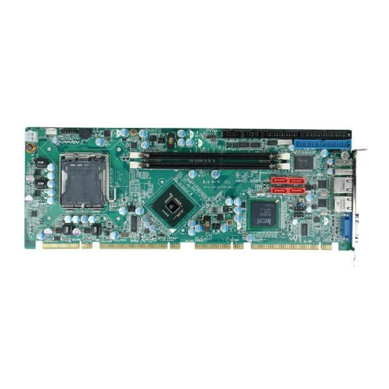
PCIE-G41A2
www.enochsystems.com
1-877-722-1116
sales@enochsystems.com
Copyright © 2013 Enoch Systems, LLC, Enoch Systems and the Enoch Systems logo are trademarks or registered trademarks of Enoch Systems, LLC and/or its affiliates in the U.S. and other countries.
Third-party trademarks mentioned are the property of their respective owners. All rights reserved.
Advertisement
Table of Contents

Related Manuals for IEI Technology PCIE-G41A2


Summary of Contents for IEI Technology PCIE-G41A2
- Page 1 Product Installation Guide terprise branch and head offices PCIE-G41A2 www.enochsystems.com 1-877-722-1116 sales@enochsystems.com Copyright © 2013 Enoch Systems, LLC, Enoch Systems and the Enoch Systems logo are trademarks or registered trademarks of Enoch Systems, LLC and/or its affiliates in the U.S. and other countries.
-
Page 2: Quick Installation Guide
PCIE-G41A2 Quick Installation Guide Version 1.0 Apr. 16, 2010 Package Contents PCIE-G41A2 package includes the following items: 1x PCIE-G41A2 Single Board Computer 1x Dual RS-232 Ports cable with bracket 1x Dual USB Ports Cable with bracket 4x SATA cable 1 x Mini Jumper Pack... -
Page 3: Output
Specifications l CPU: LGA 775 Intel® Core™ 2 Extreme/Quad/Duo, Celeron with a 1333/1066/800MHz FSB support l System Chipset: Intel® G41+ICH7R l BIOS: AMI BIOS l System Memory: 2 x 240-pin Dual-channel DDR3 1066/800MHz SDRAM Slot up to 8GB l Ethernet: Dual Realtek RTL8111CP PCIe GbE controllers (PCIe x1 Interface) l I/O Interface: 2 x RS-232... -
Page 4: Ordering Information
l Power Consumption: 3.3V@0. 53A, 5V@6.2A, 12V@0.11A, Vcore_12V@2.91A (Intel® Core™ 2 Duo E8500 3.16GHz 1333MHz FSB CPU with 2*2GB DDR3 1066MHz SDRAM) l Operation Temperature: -20°C ~ 60°C( 32°F ~ 140°F) l Operation Humidity: 5% ~ 95%, non-condensing l FAN: One 4-pin CPU FAN connector (Smart FAN) l Dimensions: 338mm X 126mm l Weight: 1.1Kg Ordering Information... - Page 5 Jumpers setting and Connectors LABEL FUNCTION J_CMOS1 Clear CMOS setting Jumper VGA1 External VGA 15-pin Female Connector USB_C1 External USB Port Connectors USB_C2 LAN1 、 LAN2 External RJ45 LAN Connectors MS/KB1 Internal PS/2 KEYBOARD/MOUSE Connector COM1 Internal Serial Port Connectors COM2 USB1 Internal USB Connector...
-
Page 6: Data-
J_CMOS1 : Clear CMOS setting Jumper J_CMOS1 DESCRIPTION Normal (Default) Clear CMOS Data VGA1 : 15-pin Female Connector PIN NO. DESCRIPTION PIN NO. DESCRIPTION GREEN BLUE DDCDAT HSYNC VSYNC DDCCLK MS/KB1: USB_C01,USB_C02 Internal 6-pin Keyboard Connector PIN NO. DESCRIPTION PIN NO. DESCRIPTION VCC(+5V) DATA-... -
Page 7: Data-
COM1,COM2: Internal Serial Port Connector PIN DESCRIPTION DESCRIPTION DCD# DSR# RTS# CTS# DTR # USB1: Internal USB Connector DESCRIPTION DESCRIPTION VCC (+5V) DATA- DATA+ DATA+ DATA- VCC (+5V) J_AUDIO1 : External Audio Module Connector DESCRIPTION DESCRIPTION ACZ_SYNC ACZ_BITCLK ACZ_SDOUT ACZ_PCBEEP ACZ_SDIN ACZ_RST# ACZ_VCC(+5V) - Page 8 SATA1~SATA4 : Serial ATA Connector PIN DESCRIPTION DESCRIPTION PIDE1: IDE Interface Connector PIN NO. DESCRIPTION PIN NO. DESCRIPTION RESET# DATA 7 DATA 8 DATA 6 DATA 9 DATA 5 DATA 10 DATA 4 DATA 11 DATA 3 DATA 12 DATA 2 DATA 13 DATA 1 DATA 14...
- Page 9 FDD1: FDC Connector PIN NO. DESCRIPTION PIN NO. DESCRIPTION REDUCE WRITE INDEX# MOTOR ENABLE A# DRIVE SELECT B# DRIVE SELECT A# MOTOR ENABLE B# DIRECTION# STEP# WRITE DATA# WRITE GATE# TRACK 0# WRITE PROTECT# READ DATA# SIDE 1 SELECT# DISK CHANGE# LPT1 : Parallel Port Connector PIN NO.
-
Page 10: Data0
F_PANEL1 : PWR、 RST Buttons、 Speaker and Indicators Function PIN DESCRIPTION PIN DESCRIPTION Function Power LED Speaker GROUND PWRBTN+ Speaker PWRBTN PWRBTN- Reset- RESET HDDLED HDLED-... -
Page 11: Data2
Board Layout: Jumper and Connector Locations...
Need help?
Do you have a question about the PCIE-G41A2 and is the answer not in the manual?
Questions and answers