Table of Contents
Advertisement
Quick Links
Advertisement
Table of Contents

Subscribe to Our Youtube Channel
Related Manuals for IEI Technology PCISA-9652


Summary of Contents for IEI Technology PCISA-9652
- Page 1 PCISA -9652 Half-Size CPU Card PCISA-9652 Half-size CPU Card Page i...
- Page 2 PCISA-9652 Half-Size CPU Card Revision Date Version Changes 2008-08 1.01 Modified part numbers of the SATA cable, SATA power cable and USB cable 2008-04 1.00 Initial Release Page ii...
- Page 3 PCISA -9652 Half-Size CPU Card Copyright COPYRIGHT NOTICE The information in this document is subject to change without prior notice in order to improve reliability, design and function and does not represent a commitment on the part of the manufacturer. In no event will the manufacturer be liable for direct, indirect, special, incidental, or consequential damages arising out of the use or inability to use the product or documentation, even if advised of the possibility of such damages.
- Page 4 Cautionary messages should also be heeded to help reduce the chance of losing data or damaging the PCISA-9652. Cautions are easy to recognize. The word “caution” is written as “CAUTION,” both capitalized and bold and is followed. The italicized text is the cautionary message.
- Page 5 PCISA -9652 Half-Size CPU Card CAUTION: This is an example of a caution message. Failure to adhere to cautions messages may result in permanent damage to the PCISA-9652. Please take caution messages seriously. NOTE: These messages inform the reader of essential but non-critical information. These messages should be read carefully as any directions or instructions contained therein can help avoid making mistakes.
-
Page 6: Packing List
PCISA-9652 from or contact an IEI sales representative directly. To contact an IEI sales representative, please send an email to sales@iei.com.tw. The items listed below should all be included in the PCISA-9652 package. 1 x PCISA-9652 CPU card 1 x IDE flat cable... -
Page 7: Table Of Contents
PCISA -9652 Half-Size CPU Card Table of Contents INTRODUCTION..................... 1 1.1 PCISA-9652 O .................... 2 VERVIEW 1.1.1 PCISA-9652 Features ..................2 1.2 PCISA-9652 B ................3 OARD VERVIEW 1.2.1 PCISA-9652 Connectors..................4 1.2.2 Technical Specifications..................6 DETAILED SPECIFICATIONS ................9 2.1 O... - Page 8 PCISA-9652 Half-Size CPU Card ® 2.6.6 Intel ICH8ME PCIe x1 Bus................23 ® 2.6.7 Intel ICH8ME Real Time Clock ..............23 ® 2.6.8 Intel ICH8ME SATA Controller ..............23 ® 2.6.9 Intel ICH8ME Serial Peripheral Interface (SPI) BIOS ......... 24 ®...
- Page 9 PCISA -9652 Half-Size CPU Card 4.1.1 PCISA-9652 Layout ..................40 4.1.2 Peripheral Interface Connectors ..............41 4.1.3 Rear Panel Connectors ..................42 4.2 I ..............43 NTERNAL ERIPHERAL ONNECTORS 4.2.1 AT Power Connector..................43 4.2.2 ATX Power Supply Enable Connector ............. 44 4.2.3 Audio Connector ....................
- Page 10 PCISA-9652 Half-Size CPU Card 5.3 CPU, CPU C DIMM I ..........77 OOLING IT AND NSTALLATION 5.3.1 Socket P CPU Installation ................77 5.3.2 Cooling Kit CF-479B-RS Installation.............. 79 5.3.3 DIMM Installation ................... 81 5.4 J ....................83 UMPER ETTINGS 5.4.1 CF Card Setup ....................
- Page 11 PCISA -9652 Half-Size CPU Card 6.3.2 IDE Configuration ..................107 6.3.2.1 IDE Master, IDE Slave ................109 6.3.3 Floppy Configuration..................114 6.3.4 Super IO Configuration...................115 6.3.5 Hardware Health Configuration..............118 6.3.6 Remote Access Configuration ................ 120 6.3.7 USB Configuration..................122 6.3.7.1 USB Mass Storage Device Configuration..........125 6.3.8 Power Configuration ..................
- Page 12 PCISA-9652 Half-Size CPU Card DIO INTERFACE....................187 C.1 DIO I ................188 NTERFACE NTRODUCTION C.2 DIO C ................... 188 ONNECTOR INOUTS C.3 A ................189 SSEMBLY ANGUAGE AMPLES C.3.1 Enable the DIO Input Function..............189 C.3.2 Enable the DIO Output Function ..............189 WATCHDOG TIMER ..................
- Page 13 PCISA -9652 Half-Size CPU Card List of Figures Figure 1-1: PCISA-9652 CPU Card................2 Figure 1-2: PCISA-9652 Board Overview (Front Side)..........3 Figure 1-2: PCISA-9652 Board Overview (Solder Side)..........4 Figure 2-1: PCISA-9652 Dimensions (mm) ...............10 Figure 2-2: External Interface Panel Dimensions (mm)...........11 Figure 2-3: Data Flow Block Diagram................12...
- Page 14 Figure 4-20: 14-Pin Serial Port Connector Locations..........66 Figure 4-21: TV Connector Pinout Locations............67 Figure 4-22: Internal USB Connector Locations ............68 Figure 4-23: PCISA-9652 External Interface Connectors ........69 Figure 4-24: VGA Connector ..................69 Figure 4-25: RJ-45 Ethernet Connector ..............71 Figure 5-1: Make sure the CPU socket retention screw is unlocked .....78 Figure 5-2: Lock the CPU Socket Retention Screw ..........79...
- Page 15 PCISA -9652 Half-Size CPU Card Figure 5-18: LAN Connection..................98 Figure 5-19: VGA Connector ..................99 Figure 5-20: USB Device Connection..............100 Figure 7-1: Introduction Screen................145 Figure 7-2: Available Drivers................... 145 Figure 7-3: Intel® Chipset Driver Directory ............146 Figure 7-4: Intel® Chipset Driver Setup Icon............147 Figure 7-5: Intel®...
- Page 16 PCISA-9652 Half-Size CPU Card Figure 7-30: Setup Type ..................162 Figure 7-31: Intel® 82573 Driver Installation Progress ........162 Figure 7-32: Select the Audio CODEC..............164 Figure 7-33: Select the OS..................165 Figure 7-34: Select the OS Version ................ 165 Figure 7-35: Locate the Setup Program Icon ............
- Page 17 PCISA -9652 Half-Size CPU Card List of Tables Table 1-1: Technical Specifications ................7 Table 2-1: Supported Intel® Processors..............13 Table 2-2: Supported HDD Specifications ..............20 Table 2-3: Power Consumption .................31 Table 3-1: Package List Contents................36 Table 3-2: Optional Items ...................37 Table 4-1: Peripheral Interface Connectors..............42 Table 4-2: Rear Panel Connectors................43 Table 4-3: AT Power Connector Pinouts ..............44 Table 4-4: ATX Power Supply Enable Connector Pinouts ........45...
- Page 18 PCISA-9652 Half-Size CPU Card Table 4-23: USB3 and USB4 Pinouts.................68 Table 4-24: VGA Connector Pinouts .................70 Table 4-25: LAN1 and LAN2 Pinouts .................70 Table 4-26: RJ-45 Ethernet Connector LEDs............71 Table 4-27: External USB Connector Pinouts ............71 Table 5-1: Jumpers......................83 Table 5-2: CF Card Setup Jumper Settings ..............84 Table 5-3: Clear CMOS Jumper Settings ..............85...
- Page 19 PCISA -9652 Half-Size CPU Card List of BIOS Menus Menu 1: Main ....................104 Menu 2: Advanced....................106 Menu 3: CPU Configuration ..................107 Menu 4: IDE Configuration ..................108 Menu 5: IDE Master and IDE Slave Configuration ..........110 Menu 6: IDE Master and IDE Slave Configuration ..........
-
Page 20: This Page Is Intentionally Left Blank
PCISA-9652 Half-Size CPU Card THIS PAGE IS INTENTIONALLY LEFT BLANK Page xx... -
Page 21: Introduction
PCISA -9652 Half-Size CPU Card Chapter Introduction Page 1... -
Page 22: Pcisa-9652 Overview
The PCISA-9652 half-size PCISA CPU card is a Socket P Intel® Core 2 Duo (Merom core) CPU platform. The PCISA-9652 has a maximum front side bus (FSB) frequency of 800 MHz and comes with a VGA interface and dual PCI Express (PCIe) Gigabit Ethernet (GbE). -
Page 23: Pcisa-9652 Board Overview
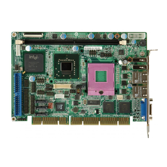
PCISA -9652 Half-Size CPU Card Supports six USB 2.0 devices Supports HDTV-Out, 24-bit dual-channel LVDS and CRT 1.2 PCISA-9652 Board Overview Figure 1-2: PCISA-9652 Board Overview (Front Side) Page 3... -
Page 24: Pcisa-9652 Connectors
PCISA-9652 Half-Size CPU Card Figure 1-3: PCISA-9652 Board Overview (Solder Side) 1.2.1 PCISA-9652 Connectors The PCISA-9652 has the following connectors on-board: 1 x Audio connector 1 x AT power connector 1 x ATX enable connector 1 x CompactFlash® card slot... - Page 25 3 x SATA II connectors 1 x SDVO connector 1 x TV out connector 2 x USB connectors The PCISA-9652 has the following connectors on the board rear panel: 1 x CRT connector 2 x Ethernet connectors 2 x USB 2.0 ports...
-
Page 26: Technical Specifications
PCISA-9652 Half-Size CPU Card 1.2.2 Technical Specifications PCISA-9652 technical specifications are listed in Table 1-1. Detailed descriptions of each specification can be found in Chapter 2. SPECIFICATION PCISA-9652 ® CPUs Supported Socket P Intel Core™2 Duo Merom core CPU Chipsets Northbridge: Intel®... -
Page 27: Table 1-1: Technical Specifications
PCISA -9652 Half-Size CPU Card Amplitude Shift Keyed IR (ASKIR) Digital I/O 8-bit digital I/O, 4 input / 4 output by super I/O Supports 7.1 channel HD audio via AC-KIT883HD audio kit Audio Ethernet Dual Intel® 82573L PCIe GbE controllers AMI BIOS Label BIOS Power... - Page 28 PCISA-9652 Half-Size CPU Card THIS PAGE IS INTENTIONALLY LEFT BLANK Page 8...
-
Page 29: Detailed Specifications
PCISA -9652 Half-Size CPU Card Chapter Detailed Specifications Page 9... -
Page 30: Overview
PCISA-9652 Half-Size CPU Card 2.1 Overview This chapter describes the specifications and on-board features of the PCISA-9652 in detail. 2.2 Dimensions 2.2.1 Board Dimensions The dimensions of the board are listed below: Length: 185.0 mm Width: 127.6 mm Figure 2-1: PCISA-9652 Dimensions (mm) -
Page 31: External Interface Panel Dimensions
Figure 2-2: External Interface Panel Dimensions (mm) 2.3 Data Flow The PCISA-9652 motherboard comes with an Intel® GME965 GMCH and an Intel® ICH8ME I/O Controller Hub. Figure 2-3 shows the data flow between the system chipset, the CPU and other components installed on the motherboard. -
Page 32: Figure 2-3: Data Flow Block Diagram
PCISA-9652 Half-Size CPU Card Figure 2-3: Data Flow Block Diagram Page 12... -
Page 33: Compatible Processors
PCISA -9652 Half-Size CPU Card 2.4 Compatible Processors Table 2-1 lists the Intel® processors supported on the PCISA-9652. All the processors in Table 2-1 are 65nm Socket P processors. Processor Max. CPU Speed FSB Speed Max. Cache Size Intel® Core ™ 2 Duo 2.60 GHz... -
Page 34: Intel ® Gme965 Memory Support
® 2.5.3 Intel GME965 Memory Support WARNING: Only DDR2 memory module can be installed on the PCISA-9652. Do not install DDR memory modules. If a DDR memory module is installed on the PCISA-9652, the PCISA-9652 may be irreparably damaged. ®... -
Page 35: Intel ® Gme965 Integrated Graphics
PCISA -9652 Half-Size CPU Card Figure 2-5: 240-pin DDR2 DIMM Socket ® 2.5.4 Intel GME965 Integrated Graphics ® The Intel® GME965 GMCH has a mobile Intel Graphics Media Accelerator X3100 integrated graphics engine that supports the following display devices: Analog CRT LVDS Analog TV-Out SDVO... -
Page 36: Intel Gme965 Analog Crt Support
PCISA-9652 Half-Size CPU Card Figure 2-6: Integrated Graphics Interfaces ® 2.5.4.1 Intel GME965 Analog CRT Support A DB-15 VGA connector on the external peripheral interface connector panel is interfaced ® ® to the Intel GME965 graphics engine. The Intel GME965 internal graphics engine, with an integrated 300 MHz RAMDAC and hot plug CRT support, supports analog CRT monitors up to QXGA (2048 x 1536). -
Page 37: Intel Gme965 Sdvo Support
PCISA -9652 Half-Size CPU Card Three integrated 10-bit DACs Overscaling NTSC and PAL formats supported Supports Component, S-Video, TV D connector or Composite output connectivity Supports with the following resolutions: SDTV 480i EDTV 480p HDTV 720p, 1080i True HDTV 1080p ®... -
Page 38: Intel ® Ich8Me I/O Controller Hub
PCISA-9652 Half-Size CPU Card Figure 2-7: DMI Chip-to-Chip Connection ® Features of the Intel GME965 DMI are listed below: 2GB/s (1GB/s in each direction) bus speed Configurable as x2 or x4 DMI lanes 32-bit downstream address ® 2.6 Intel ICH8ME I/O Controller Hub ®... -
Page 39: Intel ® Ich8Me Hd Audio Controller
PCISA -9652 Half-Size CPU Card connectors on the PCISA-9652 Supports the six USB 2.0 devices on the PCISA-9652 with four UHCI controllers and one EHCI controller Complies with System Management Bus (SMBus) Specification, Version 2.0 Supports Intel® High Definition Audio... -
Page 40: Intel ® Ich8Me Ide Interface
PCISA-9652 Half-Size CPU Card Figure 2-8: Audio Connector ® 2.6.3 Intel ICH8ME IDE Interface The integrated IDE interface on the ICH8ME supports two IDE hard disks and ATAPI devices. PIO IDE transfers up to 16 MB/s and Ultra ATA transfers of 100MB/s. The... -
Page 41: Intel ® Ich8Me Low Pin Count (Lpc) Interface
The ICH8ME is interfaced to an ITE IT8888G PCI-to-ISA bridge through the PCI bus. The ITE IT8888G PCI-to-ISA bridge is then connected to an ISA edge connector on the bottom of the PCISA-9652 thereby enabling legacy ISA card expansion on the backplane. The PCI to ISA bridge is shown in Figure 2-9. -
Page 42: Figure 2-9: Pci-To-Isa Bridge
PCISA-9652 Half-Size CPU Card Figure 2-9: PCI-to-ISA Bridge The ITE IT8888G has a PCI specification v2.1 compliant 32-bit PCI bus interface and supports both PCI Bus master and slave. The PCI interface supports both programmable positive and full subtractive decoding schemes. Some of the features of the IT8888G PCI to ISA bridge are listed below. -
Page 43: Intel ® Ich8Me Pcie X1 Bus
2.6.8 Intel ICH8ME SATA Controller The integrated SATA controller on the ICH8ME supports three SATA II drives on the PCISA-9652 with independent DMA operations. SATA controller specifications are listed below. Supports three SATA II drives Supports 3.0 Gbps data transfer speeds Supports Serial ATA Specification, Revision 1.0a... -
Page 44: Intel ® Ich8Me Serial Peripheral Interface (Spi) Bios
USB full-speed and low-speed signaling is supported by the ICH8ME integrated Universal Host Controller Interface (UHCI) controllers. Six of the eight USB ports implemented on the PCISA-9652 are connected to two internal connectors and two external connectors. See Figure 2-11. -
Page 45: Intel® 82573L Pcie Gbe Controller
PCISA -9652 Half-Size CPU Card Two PCIe x1 lanes are connected to two Intel® PCIe GbE connectors 2.7.2 Intel® 82573L PCIe GbE Controller Two RJ-45 Ethernet LAN connectors are interfaced directly to two Intel® 82573L PCIe GbE controllers. The Intel® 82573L PCIe GbE controller is a compact, single-port integrated physical layer (PHY) device with its own Memory Access Controller (MAC) and interfaced to the Intel®... -
Page 46: Lpc Bus Components
PCISA-9652 Half-Size CPU Card Mechanism for reducing interrupts from Tx/Rx operations Integrated PHY for 10/100/1000 Mbps (full- and half-duplex) IEEE 802.3ab* auto-negotiation support IEEE 802.3ab PHY compliance and compatibility Tx/Rx IP,TCP,and UDP checksum offloading Tx TCP segmentation IEEE 802.1q* Virtual Local Area Network (VLAN) support with VLAN tag... -
Page 47: Super I/O Lpc Interface
PCISA -9652 Half-Size CPU Card The iTE IT8712F is an LPC interface-based Super I/O device that comes with Environment Controller integration. Some of the features of the iTE IT8712F chipset are listed below: LPC Interface PC98/99/2001, ACPI and LANDesk Compliant Enhanced Hardware Monitor Fan Speed Controller SmartGuardian Controller... -
Page 48: Super I/O Fan Speed Controller
2.8.2.5 Super I/O GPIO Ports The Super I/O has 38 programmable GPIO pins of which 8 are implemented on the PCISA-9652. The GPIO connector has 8 programmable bits, 4-bit input and 4-bit output. 2.8.2.6 Super I/O Infrared The Super I/O has dedicated infrared (IrDA) pins that are interfaced to an IrDA connector. -
Page 49: Super I/O Floppy Disk Drive (Fdd) Controller
500Kbps 1Mbps 2Mbps 3-mode FDD drives supported The FDD controller is interfaced to a FDD connector on the PCISA-9652. 2.9 Environmental and Power Specifications 2.9.1 System Monitoring Three thermal inputs on the PCISA-9652 Super I/O Enhanced Hardware Monitor monitor the following temperatures:... -
Page 50: Operating Temperature And Temperature Control
PCISA-9652 Half-Size CPU Card Eight voltage inputs on the PCISA-9652 Super I/O Enhanced Hardware Monitor monitor the following voltages: CPU Core +1.8V +3.30V +5.00V +12.0V +1.05V +1.5V +1.25V VBAT The PCISA-9652 Super I/O Enhanced Hardware Monitor also monitors the following fan... -
Page 51: Table 2-3: Power Consumption
PCISA -9652 Half-Size CPU Card Table 2-3 shows the power consumption parameters for the PCISA-9652 running with a 2.0GHz Intel® Core™2 Duo T7300 with a 800 MHz FSB and a 667 MHz 1 GB DDR2 DIMM, Voltage Current 7.72 A +12V 0.139 A... - Page 52 PCISA-9652 Half-Size CPU Card THIS PAGE IS INTENTIONALLY LEFT BLANK Page 32...
-
Page 53: Unpacking
PCISA -9652 Half-Size CPU Card Chapter Unpacking Page 33... -
Page 54: Anti-Static Precautions
When the PCISA-9652 is unpacked, please do the following: Follow the anti-static precautions outlined in Section 3.1. Make sure the packing box is facing upwards so the PCISA-9652 does not fall out of the box. Make sure all the components shown in Section 3.3 are present. -
Page 55: Unpacking Checklist
If some of the components listed in the checklist below are missing, please do not proceed with the installation. Contact the IEI reseller or vendor you purchased the PCISA-9652 from or contact an IEI sales representative directly. To contact an IEI sales representative, please send an email to sales@iei.com.tw. -
Page 56: Optional Items
The items listed in this section are optional items that must be ordered separately. Please contact your PCISA-9652 vendor, distributor or reseller for more information or, contact IEI directly by sending an email to sales@iei.com.tw. The following optional items are available for the PCISA-9652. Quantity Item and Part Number Image 7.1 Channel HD audio kit with Realtek... -
Page 57: Table 3-2: Optional Items
PCISA -9652 Half-Size CPU Card Quantity Item and Part Number Image CPU Cooler (P/N: CF-479B-RS) FDD cable (P/N: 32200-000058-RS) KB/MS cable with bracket (P/N: 19800-000075-RS) HDTV cable set with S-Video/Composite/Component interfaces (P/N: HDTVCABLESET-01) RS-232/422/485 cable (P/N: 32200-000077-RS) Table 3-2: Optional Items Page 37... - Page 58 PCISA-9652 Half-Size CPU Card THIS PAGE IS INTENTIONALLY LEFT BLANK Page 38...
-
Page 59: Connectors And Jumpers
PCISA -9652 Half-Size CPU Card Chapter Connectors and Jumpers Page 39... -
Page 60: Peripheral Interface Connectors
PCISA-9652 Half-Size CPU Card 4.1 Peripheral Interface Connectors Section 4.1.1 shows peripheral interface connector locations. Section 4.1.2 lists all the peripheral interface connectors seen in Section 4.1.1. 4.1.1 PCISA-9652 Layout Figure 4-1 shows the on-board peripheral connectors, backplane peripheral connectors and on-board jumpers. -
Page 61: Peripheral Interface Connectors
PCISA -9652 Half-Size CPU Card Figure 4-2: Connector and Jumper Locations (Solder Side) 4.1.2 Peripheral Interface Connectors Table 4-1 shows a list of the peripheral interface connectors on the PCISA-9652. Detailed descriptions of these connectors can be found in Section 4.2. Connector... -
Page 62: Rear Panel Connectors
8-pin header USB01 USB connector (2) 8-pin header USB23 Table 4-1: Peripheral Interface Connectors 4.1.3 Rear Panel Connectors Table 4-2 lists the rear panel connectors on the PCISA-9652. Detailed descriptions of these connectors can be found in Section 4.3. Page 42... -
Page 63: Internal Peripheral Connectors
Internal peripheral connectors are found on the motherboard and are only accessible when the motherboard is outside of the chassis. This section has complete descriptions of all the internal, peripheral connectors on the PCISA-9652. 4.2.1 AT Power Connector CN Label:... -
Page 64: Atx Power Supply Enable Connector
4.2.2 ATX Power Supply Enable Connector CN Label: ATXCTL1 3-pin wafer (1x3) CN Type: CN Location: See Figure 4-4 CN Pinouts: See Table 4-4 The ATX power supply enable connector enables the PCISA-9652 to be connected to an ATX power supply. Page 44... -
Page 65: Audio Connector
PCISA -9652 Half-Size CPU Card Figure 4-4: ATX Power Supply Enable Connector Location PIN NO. DESCRIPTION PS-ON +5V Standby Table 4-4: ATX Power Supply Enable Connector Pinouts 4.2.3 Audio Connector CN Label: J_AUDIO1 10-pin header (2x5) CN Type: CN Location: See Figure 4-5 CN Pinouts: See Table 4-5... -
Page 66: Compactflash® Socket
PCISA-9652 Half-Size CPU Card Figure 4-5: Audio Connector Location PIN NO. DESCRIPTION PIN NO. DESCRIPTION HDA_SYNC HDA_BITCLK HDA_SDOUT SB_SPKR HDA_SDIN0 HDA_RST# +12V Table 4-5: Audio Connector Pinouts 4.2.4 CompactFlash® Socket CN Label: CF1 (solder side) CN Type: 50-pin slot (2x25) -
Page 67: Figure 4-5: Cf Card Socket Location
PCISA -9652 Half-Size CPU Card Figure 4-6: CF Card Socket Location Page 47... -
Page 68: Digital Input/Output Connector
PCISA-9652 Half-Size CPU Card PIN NO. DESCRIPTION PIN NO. DESCRIPTION GROUND VCC-IN CHECK1 DATA 3 DATA 11 DATA 4 DATA 12 DATA 5 DATA 13 DATA 6 DATA 14 DATA 7 DATA 15 HDC_CS0# HDC_CS1 GROUND IOR# IOW# VCC_COM IRQ15... -
Page 69: Fan Connectors
See Table 4-7 The DIO connector is managed through a Super I/O chip. The DIO connector pins are user programmable. The digital IO port of PCISA-9652 is 5V CMOS level. Figure 4-7: GPIO Connector Location PIN NO. DESCRIPTION PIN NO. DESCRIPTION... -
Page 70: Floppy Disk Connector (34-Pin)
PCISA-9652 Half-Size CPU Card CN Pinouts: See Table 4-8 The cooling fan connector provides a 12V, 500mA current to a CPU cooling fan. The connector has a "rotation" pin to get rotation signals from fans and notify the system so the system BIOS can recognize the fan speed. -
Page 71: Figure 4-8: 34-Pin Fdd Connector Location
PCISA -9652 Half-Size CPU Card CN Location: See Figure 4-9 CN Pinouts: See Table 4-9 The floppy disk connector is connected to a floppy disk drive. Figure 4-9: 34-pin FDD Connector Location PIN NO. DESCRIPTION PIN NO. DESCRIPTION REDUCE WRITE INDEX# MOTOR ENABLE A# DRIVE SELECT B#... -
Page 72: Flash Spi Rom Connector
PCISA-9652 Half-Size CPU Card WRITE PROTECT# READ DATA# SIDE 1 SELECT# DISK CHANGE# Table 4-9: 34-pin FDD Connector Pinouts 4.2.8 Flash SPI ROM Connector CN Label: JSPI1 CN Type: 8-pin header (2x4) CN Location: See Figure 4-23 CN Pinouts: See Table 4-23 Use the Flash SPI ROM connector to flash SPI ROM. -
Page 73: Front Panel Connector
PCISA -9652 Half-Size CPU Card Table 4-10: Flash SPI ROM Connector Pinouts 4.2.9 Front Panel Connector CN Label: F_PANEL1 8-pin header (2x4) CN Type: CN Location: See Figure 4-11 CN Pinouts: See Table 4-11 The front panel connector connects to several external switches and indicators to monitor and control the motherboard. -
Page 74: Ide Connector
40-pin box header (2x20) CN Location: See Figure 4-12 CN Pinouts: See Table 4-12 One primary 40-pin IDE device connector on the PCISA-9652 motherboard supports connectivity to ATA 100/66/33 IDE devices with data transfer rates up to 100MB/s. Page 54... -
Page 75: Figure 4-11: Ide Device Connector Location
PCISA -9652 Half-Size CPU Card Figure 4-12: IDE Device Connector Location PIN NO. DESCRIPTION PIN NO. DESCRIPTION RESET# DATA 7 DATA 8 DATA 6 DATA 9 DATA 5 DATA 10 DATA 4 DATA 11 DATA 3 DATA 12 DATA 2 DATA 13 DATA 1 DATA 14... -
Page 76: Infrared Interface Connector
PCISA-9652 Half-Size CPU Card PIN NO. DESCRIPTION PIN NO. DESCRIPTION HDD ACTIVE# Table 4-12: IDE Connector Pinouts 4.2.11 Infrared Interface Connector CN Label: CN Type: 5-pin header (1x5) CN Location: See Figure 4-13 CN Pinouts: See Table 4-13 The infrared interface connector supports both Serial Infrared (SIR) and Amplitude Shift Key Infrared (ASKIR) interfaces. -
Page 77: Keyboard/Mouse Connector
PCISA -9652 Half-Size CPU Card 4.2.12 Keyboard/Mouse Connector CN Label: KB_MS1 CN Type: 6-pin header (1x6) CN Location: See Figure 4-14 CN Pinouts: See Table 4-14 The keyboard/mouse connector can be connected to a standard PS/2 cable or PS/2 Y cable to add keyboard and mouse functionality to the system. -
Page 78: Lvds Lcd Connector
PCISA-9652 Half-Size CPU Card CN Location: See Figure 4-15 CN Pinouts: See Table 4-15 The LCD backlight connector is for the LCD inverter connection. Figure 4-15: LCD Backlight Connector Location PIN NO. DESCRIPTION BRIGHTNESS GND1 GND2 BL_EN Table 4-15: LCD Backlight Connector Pinouts 4.2.14 LVDS LCD connector... -
Page 79: Figure 4-15: Lvds Lcd Connector Location
PCISA -9652 Half-Size CPU Card CN Pinouts: See Table 4-16 The connector supports one or two channel 24-bit LVDS panel. Figure 4-16: LVDS LCD Connector Location PIN NO. DESCRIPTION PIN NO. DESCRIPTION LVDS data0 output + LVDS data0 output - LVDS data1 output + LVDS data1 output - LVDS data2 output +... -
Page 80: Parallel Port Connector
PCISA-9652 Half-Size CPU Card PIN NO. DESCRIPTION PIN NO. DESCRIPTION LVDS data2 output + LVDS data2 output - LVDS clock output + LVDS clock output - LVDS data3 output + LVDS data3 output - +LCD (3.3V or 5V) +LCD (3.3V or 5V) +LCD (3.3V or 5V) -
Page 81: Sata Drive Connectors
PCISA -9652 Half-Size CPU Card PIN NO. DESCRIPTION PIN NO. DESCRIPTION STROBE# DATA 0 DATA 1 DATA 2 DATA 3 DATA 4 DATA 5 DATA 6 DATA 7 ACKNOWLEDGE BUSY PAPER EMPTY PRINTER SELECT AUTO FORM FEED # ERROR# INITIALIZE PRINTER SELECT LN# GROUND GROUND... -
Page 82: Sdvo Connector
PCISA-9652 Half-Size CPU Card Figure 4-18: SATA Drive Connector Locations PIN NO. DESCRIPTION Table 4-18: SATA Drive Connector Pinouts 4.2.17 SDVO Connector CN Label: CN Type: 47-pin connector (1x47) CN Location: See Figure 4-19 CN Pinouts: See Table 4-19 The 47-pin SDVO (Serial Digital Video Out) connector supports additional video signaling interfaces. -
Page 83: Figure 4-18: Sdvo Connector Pinout Locations
PCISA -9652 Half-Size CPU Card Figure 4-19: SDVO Connector Pinout Locations PIN NO. DESCRIPTION PIN NO. DESCRIPTION GROUND GROUND SDVOC_CLK- SDVOB_BLUE- SDVOC_CLK+ SDVOB_BLUE+ GROUND GROUND SDVOC_GREEN- SDVOB_RED- SDVOC_GREEN+ SDVOB_RED+ GROUND GROUND Page 63... -
Page 84: Serial Port Connector (Com 1, Rs-232)
PCISA-9652 Half-Size CPU Card SDVOB_CLK- SDVO1_STALL- SDVOB_ CLK+ SDVO1_STALL+ GROUND GROUND SDVOB_GREEN- SDVO_TVCLKIN- SDVOB_GREEN+ SDVO_TVCLKIN+ GROUND GROUND SDVOC_INT+ SDVO_CLK SDVOC_INT+ SDVO_DATA GROUND PCIRST SDVOB_INT+ +5VS SDVOB_INT+ +5VS GROUND +5VS SDVOC_BLUE- SDVOC_BLUE+ GROUND GROUND SDVOC_RED- GROUND SDVOC_RED+ Table 4-19: SDVO Connector Pinouts 4.2.18 Serial Port Connector (COM 1, RS-232) -
Page 85: Serial Port Connector (Com 2, Rs-232/422/485)
PCISA -9652 Half-Size CPU Card Figure 4-20: RS-232 Connector Pinout Locations PIN NO. DESCRIPTION PIN NO. DESCRIPTION Data Carrier Direct (DCD) Data Set Ready (DSR) Receive Data (RXD) Request To Send (RTS) Transmit Data (TXD) Clear To Send (CTS) Data Terminal Ready (DTR) Ring Indicator (RI) Ground (GND) Ground (GND) -
Page 86: Tv Out Connector
PCISA-9652 Half-Size CPU Card Figure 4-21: 14-Pin Serial Port Connector Locations PIN NO. DESCRIPTION PIN NO. DESCRIPTION TXD 485+ TXD 485# RXD 485+ RXD 485# Table 4-21: COM 2 Pinouts 4.2.20 TV Out Connector CN Label: CN Type: 6-pin header (2x3) -
Page 87: Internal Usb Connectors
PCISA -9652 Half-Size CPU Card Figure 4-22: TV Connector Pinout Locations S-Video Connector PIN NO. DESCRIPTION PIN NO. DESCRIPTION AGREEN_Y ARED_C RCA Connector (only video signal) ABLUE_CVBS Table 4-22: TV Port Connector Pinouts 4.2.21 Internal USB Connectors CN Label: USB01 and USB23 CN Type: 8-pin header (2x4) CN Location:... -
Page 88: Figure 4-22: Internal Usb Connector Locations
PCISA-9652 Half-Size CPU Card Figure 4-23: Internal USB Connector Locations PIN NO. DESCRIPTION PIN NO. DESCRIPTION 5V_STANDBY DATA- DATA+ DATA+ DATA- 5V_STANDBY Table 4-23: USB3 and USB4 Pinouts Page 68... -
Page 89: External Interface Connectors
4.3 External Interface Connectors The peripheral connectors on the back panel are connected to devices externally when the PCISA-9652 is installed in a chassis. The peripheral connectors on the rear panel are: 1 x CRT connector 2 x RJ-45 Ethernet connectors 2 x USB 2.0 connectors... -
Page 90: Ethernet Connectors
CN Pinouts: See Table 4-25 The PCISA-9652 is equipped with two built-in GbE Ethernet controllers. The controllers can connect to the LAN through two RJ-45 LAN connectors. There are two LEDs on the connector indicating the status of LAN. The pin assignments are listed in the following... -
Page 91: Usb Connector
PCISA -9652 Half-Size CPU Card Figure 4-26: RJ-45 Ethernet Connector The RJ-45 Ethernet connector has two status LEDs, one green and one yellow. The green LED indicates activity on the port and the yellow LED indicates the port is linked. See Table 4-26. - Page 92 PCISA-9652 Half-Size CPU Card THIS PAGE IS INTENTIONALLY LEFT BLANK Page 72...
-
Page 93: Installation
PCISA -9652 Half-Size CPU Card Chapter Installation Page 73... -
Page 94: Anti-Static Precautions
Electrostatic discharge (ESD) can cause serious damage to electronic components, including the PCISA-9652. Dry climates are especially susceptible to ESD. It is therefore critical that whenever the PCISA-9652, or any other electrical component is handled, the following anti-static precautions are strictly adhered to. -
Page 95: Installation Considerations
PCISA-9652 is installed. All installation notices pertaining to the installation of the PCISA-9652 should be strictly adhered to. Failing to adhere to these precautions may lead to severe damage of the PCISA-9652 and injury to the person installing the motherboard. 5.2.1 Installation Notices... -
Page 96: Installation Checklist
Allow screws to come in contact with the PCB circuit, connector pins, or its components. 5.2.2 Installation Checklist The following checklist is provided to ensure the PCISA-9652 is properly installed. All the items in the packing list are present The CPU is installed... -
Page 97: Cpu, Cpu Cooling Kit And Dimm Installation
Running a CPU without a cooling kit may also result in injury to the user. The CPU, CPU cooling kit and DIMM are the most critical components of the PCISA-9652. If one of these component is not installed the PCISA-9652 cannot run. -
Page 98: Figure 5-1: Make Sure The Cpu Socket Retention Screw Is Unlocked
PCISA-9652 Half-Size CPU Card CPU socket should be in the unlocked position. If it is not in the unlocked position, use a screwdriver to unlock the screw. See Figure 5-1. Figure 5-1: Make sure the CPU socket retention screw is unlocked Step 2: Inspect the CPU socket. -
Page 99: Cooling Kit Cf-479B-Rs Installation
PCISA -9652 Half-Size CPU Card Figure 5-2: Lock the CPU Socket Retention Screw 5.3.2 Cooling Kit CF-479B-RS Installation Figure 5-3: IEI CF-479B-RS Cooling Kit An IEI Socket P CPU cooling kit can be purchased separately. The cooling kit comprises a CPU heat sink and a cooling fan. -
Page 100: Figure 5-4: Cooling Kit Support Bracket
PCISA-9652 Half-Size CPU Card WARNING: Do not wipe off (accidentally or otherwise) the pre-sprayed layer of thermal paste on the bottom of the CF-479B-RS heat sink. The thermal paste between the CPU and the heat sink is important for optimum heat dissipation. -
Page 101: Dimm Installation
Figure 5-5: Connect the cooling fan cable 5.3.3 DIMM Installation WARNING: Only DDR2 memory module can be installed on the PCISA-9652. Do not install DDR memory modules. If a DDR memory module is installed on the PCISA-9652, the PCISA-9652 may be irreparably damaged. -
Page 102: Figure 5-6: Installing A Dimm
PCISA-9652 Half-Size CPU Card CAUTION: The DIMM1 socket must be installed with one DDR2 DIMM to enable the PCISA-9652 to boot-up properly. To install a DIMM into a DIMM socket, please follow the steps below and refer to Figure 5-6. -
Page 103: Jumper Settings
OPEN a jumper means removing the Figure 5-7: Jumper Locations plastic clip from a jumper. Before the PCISA-9652 is installed in the system, the jumpers must be set in accordance with the desired configuration. The jumpers on the PCISA-9652 are listed in Table 5-1. Description... -
Page 104: Cf Card Setup
PCISA-9652 Half-Size CPU Card 5.4.1 CF Card Setup Jumper Label: JCF1 Jumper Type: 2-pin header Jumper Settings: See Table 5-2 Jumper Location: See Figure 5-8 The CF Card Setup jumper sets the CF Type I card or CF Type II cards as either the slave device or the master device. -
Page 105: Clear Cmos Jumper
Jumper Location: See Figure 5-9 If the PCISA-9652 fails to boot due to improper BIOS settings, the clear CMOS jumper clears the CMOS data and resets the system BIOS information. To do this, use the jumper cap to close pins 2 and 3 for a few seconds then reinstall the jumper clip back to pins 1 and 2. -
Page 106: Com 2 Function Select Jumper
PCISA-9652 Half-Size CPU Card Figure 5-9: Clear CMOS Jumper 5.4.3 COM 2 Function Select Jumper Jumper Label: Jumper Type: 6-pin header Jumper Settings: See Table 5-4 Jumper Location: See Figure 5-10 The COM 2 Function Select jumper sets the communication protocol used by the second serial communications port (COM 2) as RS-232, RS-422 or RS-485. -
Page 107: Lvds Voltage Selection
Figure 5-10: COM 2 Function Select Jumper Location 5.4.4 LVDS Voltage Selection WARNING: Permanent damage to the screen and PCISA-9652 may occur if the wrong voltage is selected with this jumper. Please refer to the user guide that cam with the monitor to select the correct voltage. -
Page 108: Lvds Panel Resolution Selection
PCISA-9652 Half-Size CPU Card LVDS Voltage Select Description Short 1-2 Default Short 2-3 Table 5-5: LVDS Voltage Selection Jumper Settings The LVDS Voltage Selection jumper location is shown in Figure 5-11. Figure 5-11: LVDS Voltage Selection Jumper Pinout Locations 5.4.5 LVDS Panel Resolution Selection... -
Page 109: Figure 5-12: Lvds Resolution Selection Jumper Pinout Locations
PCISA -9652 Half-Size CPU Card Short 1-2 & 3-4 1024 x 768 (24-bit) Short 5-6 1024 x 768 (48-bit) Short 1-2 & 5-6 1280 x 1024 (48-bit) Short 3-4 & 5-6 1600 x 1200 (48-bit) Short 1-2 & 3-4 & 5-6 1280 x 768 (18-bit) Short 7-8 1280 x 800 (18-bit) -
Page 110: Chassis Installation
The PCISA-9652 must be installed in a chassis with ventilation holes on the sides allowing airflow to travel through the heat sink surface. In a system with an individual power supply unit, the cooling fan of a power supply can also help generate airflow through the board surface. -
Page 111: Cpu Card Installation
5.5.3 CPU Card Installation To install the PCISA-9652 CPU card onto the backplane, carefully align the CPU card interface connectors with the corresponding socket on the backplane. To do this, please refer to the reference material that came with the backplane. Next, secure the CPU card to the chassis. -
Page 112: Ide Cable Connection
PCISA-9652 Half-Size CPU Card HDTV/TV cable with S-Video/Composite/Component output 5.6.2 IDE Cable Connection The IDE flat cable connects to the PCISA-9652 to one or two IDE devices. To connect an IDE HDD to the PCISA-9652, please follow the instructions below. Step 1: Locate the IDE connector. -
Page 113: Figure 5-14: Sata Drive Cable Connection
PCISA -9652 Half-Size CPU Card The PCISA-9652 is shipped with two SATA drive cables and one SATA drive power cable. To connect the SATA drives to the connectors, please follow the steps below. Step 1: Locate the connectors. The locations of the SATA drive connectors are shown in Chapter 3. -
Page 114: Usb Cable (Dual Port) With Slot Bracket
Align the connectors. The cable has two connectors. Correctly align pin 1on each cable connector with pin 1 on the PCISA-9652 USB connector. Step 3: Insert the cable connectors. Once the cable connectors are properly aligned with the USB connectors on the PCISA-9652, connect the cable connectors to Page 94... -
Page 115: Channel Audio Kit Installation (Optional)
The optional 7.1 channel audio kit connects to the 10-pin audio connector on the PCISA-9652. The audio kit consists of five audio jacks. One audio jack, Mic In, connects to a microphone. The remaining four audio jacks, Line-In, Front-Out, Rear-Out, and... -
Page 116: Figure 5-17: 7.1 Channel Audio Kit
Connect the audio kit cable. The audio kit is shipped with a cable that connects the audio kit to the PCISA-9652. Connect the cable to the connector on the back of the audio kit. Make sure the pins are properly aligned (i.e. pin 1 connects to pin 1). -
Page 117: External Peripheral Interface Connection
USB devices VGA monitor To install these devices, connect the corresponding cable connector from the actual device to the corresponding PCISA-9652 external peripheral interface connector making sure the pins are properly aligned. 5.7.1 LAN Connection (Single Connector) There are two external RJ-45 LAN connectors. The RJ-45 connectors enable connection to an external network. -
Page 118: Vga Monitor Connection
Step 0: 5.7.2 VGA Monitor Connection The PCISA-9652 has a single female DB-15 connector on the external peripheral interface panel. The DB-15 connector is connected to a CRT or VGA monitor. To connect a monitor to the PCISA-9652, please follow the instructions below. -
Page 119: Usb Device Connection (Single Connector)
Step 0: 5.7.3 USB Device Connection (Single Connector) There are two external USB 2.0 connectors. Both connectors are perpendicular to the PCISA-9652. To connect a USB 2.0 or USB 1.1 device, please follow the instructions below. Step 1: Located the USB connectors. The locations of the USB connectors are shown in Chapter 4. -
Page 120: Figure 5-20: Usb Device Connection
PCISA-9652 Half-Size CPU Card Figure 5-20: USB Device Connection Step 3: Insert the device connector. Once aligned, gently insert the USB device connector into the on-board connector. Step 0: Page 100... -
Page 121: Ami Bios
PCISA -9652 Half-Size CPU Card Chapter AMI BIOS Page 101... -
Page 122: Introduction
PCISA-9652 Half-Size CPU Card 6.1 Introduction A licensed copy of AMI BIOS is preprogrammed into the ROM BIOS. The BIOS setup program allows users to modify the basic system configuration. This chapter describes how to access the BIOS setup program and the configuration options that may be changed. -
Page 123: Getting Help
PCISA -9652 Half-Size CPU Card F1 key General help, only for Status Page Setup Menu and Option Page Setup Menu F2 /F3 key Change color from total 16 colors. F2 to select color forward. F10 key Save all the CMOS changes, only for Main Menu Table 6-1: BIOS Navigation Keys 6.1.3 Getting Help When F1 is pressed a small help window describing the appropriate keys to use and the... -
Page 124: Main
PCISA-9652 Half-Size CPU Card 6.2 Main The Main BIOS menu (BIOS Menu 1) appears when the BIOS Setup program is entered. The Main menu gives an overview of the basic system information. BIOS Menu 1: Main System Overview The System Overview lists a brief summary of different system components. The fields in System Overview cannot be changed. -
Page 125: Advanced
PCISA -9652 Half-Size CPU Card Count: The number of CPUs on the motherboard System Memory: Displays the auto-detected system memory. Size: Lists memory size The System Overview field also has two user configurable fields: System Time [xx:xx:xx] Use the System Time option to set the system time. Manually enter the hours, minutes and seconds. -
Page 126: Cpu Configuration
PCISA-9652 Half-Size CPU Card BIOS Menu 2: Advanced 6.3.1 CPU Configuration Use the CPU Configuration menu (BIOS Menu 3) to view detailed CPU specifications and configure the CPU. Page 106... -
Page 127: Ide Configuration
PCISA -9652 Half-Size CPU Card BIOS Menu 3: CPU Configuration The CPU Configuration menu (BIOS Menu 3) lists the following CPU details: Manufacturer: Lists the name of the CPU manufacturer Brand String: Lists the brand name of the CPU being used Frequency: Lists the CPU processing speed FSB Speed: Lists the FSB speed Cache L1: Lists the CPU L1 cache size... -
Page 128: Menu 4: Ide Configuration
PCISA-9652 Half-Size CPU Card BIOS Menu 4: IDE Configuration ATA/IDE Configurations [Compatible] Use the ATA/IDE Configurations option to configure the ATA/IDE controller. Disables the on-board ATA/IDE controller. Disabled Compatible Configures the on-board ATA/IDE controller to be in EFAULT compatible mode. In this mode, a SATA channel will replace one of the IDE channels. -
Page 129: Ide Master, Ide Slave
PCISA -9652 Half-Size CPU Card Legacy IDE Channels [SATA Pri, PATA Sec] SATA Only SATA Pri., PATA Sec EFAULT PATA Only IDE Master and IDE Slave When entering setup, BIOS auto detects the presence of IDE devices. BIOS displays the status of the auto detected IDE devices. -
Page 130: Menu 5: Ide Master And Ide Slave Configuration
PCISA-9652 Half-Size CPU Card BIOS Menu 5: IDE Master and IDE Slave Configuration Type [Auto] Use the Type BIOS option select the type of device the AMIBIOS attempts to boot from after the Power-On Self-Test (POST) is complete. Not Installed BIOS is prevented from searching for an IDE disk drive on the specified channel. - Page 131 PCISA -9652 Half-Size CPU Card IDE disk drives on the specified channel. ARMD This option specifies an ATAPI Removable Media Device. These include, but are not limited to: LS-120 LBA/Large Mode [Auto] Use the LBA/Large Mode option to disable or enable BIOS to auto detects LBA (Logical Block Addressing).
- Page 132 PCISA-9652 Half-Size CPU Card PIO Mode [Auto] Use the PIO Mode option to select the IDE PIO (Programmable I/O) mode program timing cycles between the IDE drive and the programmable IDE controller. As the PIO mode increases, the cycle time decreases.
- Page 133 PCISA -9652 Half-Size CPU Card MWDMA0 Multi Word DMA mode 0 selected with a maximum data transfer rate of 4.2MBps Multi Word DMA mode 1 selected with a maximum data MWDMA1 transfer rate of 13.3MBps MWDMA2 Multi Word DMA mode 2 selected with a maximum data transfer rate of 16.6MBps UDMA1 Ultra DMA mode 0 selected with a maximum data transfer...
-
Page 134: Floppy Configuration
PCISA-9652 Half-Size CPU Card Auto BIOS auto detects HDD SMART support. EFAULT Disabled Prevents BIOS from using the HDD SMART feature. Enabled Allows BIOS to use the HDD SMART feature 32Bit Data Transfer [Enabled] Use the 32Bit Data Transfer BIOS option to enables or disable 32-bit data transfers. -
Page 135: Super Io Configuration
PCISA -9652 Half-Size CPU Card Floppy A Use the Floppy A option to configure the floppy disk drive. Options are listed below: Disabled 360 KB 51/4” 1.2 MB 51/4” 720 KB 31/2” 1.44 MB 31/2’ 2.88 MB 31/2” 6.3.4 Super IO Configuration Use the Super IO Configuration menu (BIOS Menu 7) to set or change the configurations for the FDD controllers, parallel ports and serial ports. - Page 136 PCISA-9652 Half-Size CPU Card Serial Port1 Address [3F8/IRQ4] Use the Serial Port1 Address option to select the Serial Port 1 base address. Disabled No base address is assigned to Serial Port 1 3F8/IRQ4 Serial Port 1 I/O port address is 3F8 and the interrupt...
- Page 137 PCISA -9652 Half-Size CPU Card 2E8/IRQ3 Serial Port 2 I/O port address is 2E8 and the interrupt address is IRQ3 Serial Port2 Mode [Normal] Use the Serial Port2 Mode option to select the Serial Port2 operational mode. Normal Serial Port 2 mode is normal EFAULT IrDA Serial Port 2 mode is IrDA...
-
Page 138: Hardware Health Configuration
PCISA-9652 Half-Size CPU Card Normal mode. The parallel port operates in the extended capabilities port (ECP) mode. The ECP mode supports bi-directional communication between the system and the parallel port device and the transmission rates between the two are much faster... -
Page 139: Menu 8: Hardware Health Configuration
PCISA -9652 Half-Size CPU Card BIOS Menu 8: Hardware Health Configuration The following system parameters and values are shown. The system parameters that are monitored are: System Temperatures: The following system temperatures are monitored CPU Temperature PWM Temperature System Temperature Fan Speeds: The CPU cooling fan speed is monitored. -
Page 140: Remote Access Configuration
PCISA-9652 Half-Size CPU Card +1.05V +1.5V +1.25V VBAT 6.3.6 Remote Access Configuration Use the Remote Access Configuration menu (BIOS Menu 9) to configure remote access parameters. The Remote Access Configuration is an AMIBIOS feature and allows a remote host running a terminal program to display and configure the BIOS settings. - Page 141 PCISA -9652 Half-Size CPU Card Disabled Remote access is disabled. EFAULT Enabled Remote access configuration options shown below appear: Serial Port Number Serial Port Mode Redirection after BIOS POST Terminal Type These configuration options are discussed below. Serial Port Number [COM1] Use the Serial Port Number option allows users to select the serial port used for remote access.
-
Page 142: Usb Configuration
PCISA-9652 Half-Size CPU Card 38400 8,n,1 19200 8,n,1 09600 8,n,1 NOTE: Identical baud rate setting musts be set on the host (a management computer running a terminal software) and the slave Redirection After BIOS POST [Always] Use the Redirection After BIOS POST option to specify when console redirection should occur. -
Page 143: Menu 10: Usb Configuration
PCISA -9652 Half-Size CPU Card BIOS Menu 10: USB Configuration USB Configuration The USB Configuration field shows the system USB configuration. The items listed are: Module Version: x.xxxxx.xxxxx USB Devices Enabled The USB Devices Enabled field lists the USB devices that are enabled on the system USB Function [Enabled] Use the USB Function BIOS option to enable or disable the USB function. - Page 144 PCISA-9652 Half-Size CPU Card Legacy USB Support [Enabled] Use the Legacy USB Support BIOS option to enable USB mouse and USB keyboard support. Normally if this option is not enabled, any attached USB mouse or USB keyboard does not become available until a USB compatible operating system is fully booted with all USB drivers loaded.
-
Page 145: Usb Mass Storage Device Configuration
PCISA -9652 Half-Size CPU Card 6.3.7.1 USB Mass Storage Device Configuration Use the USB Mass Storage Device Configuration menu (BIOS Menu 11) to configure USB mass storage class devices. BIOS Menu 11: USB Mass Storage Device Configuration USB Mass Storage Reset Delay [20 Sec] Use the USB Mass Storage Reset Delay option to set the number of seconds POST waits for the USB mass storage device after the start unit command. - Page 146 PCISA-9652 Half-Size CPU Card device after the start unit command. 40 Sec POST waits 40 seconds for the USB mass storage device after the start unit command. Device ## The Device## field lists the USB devices that are connected to the system.
-
Page 147: Power Configuration
PCISA -9652 Half-Size CPU Card floppy image. This option works only for drives formatted with FAT12, FAT16 or FAT32. Hard Disk Allows the USB device to be emulated as hard disk responding to INT13h calls that return DL values of 80h or above. -
Page 148: Pci/Pnp
PCISA-9652 Half-Size CPU Card Power Supply Mode [ATX] Use the Power Supply Mode BIOS option to select the power supply that is connected to the system. An AT power supply is connected to the system An ATX power supply is connected to the system... - Page 149 PCISA -9652 Half-Size CPU Card IRQ# Use the IRQ# address to specify what IRQs can be assigned to a particular peripheral device. Available The specified IRQ is available to be used by PCI/PnP devices Reserved The specified IRQ is reserved for use by Legacy ISA devices Available IRQ addresses options are: IRQ3...
-
Page 150: Boot
PCISA-9652 Half-Size CPU Card DM Channel 1 DM Channel 3 DM Channel 5 DM Channel 6 DM Channel 7 Reserved Memory Size [Disabled] Use the Reserved Memory Size BIOS option to specify the amount of memory that should be reserved for legacy ISA devices. -
Page 151: Boot Settings Configuration
PCISA -9652 Half-Size CPU Card BIOS Menu 14: Boot 6.5.1 Boot Settings Configuration Use the Boot Settings Configuration menu (BIOS Menu 15) to configure advanced system boot options. Page 131... -
Page 152: Menu 15: Boot Settings Configuration
PCISA-9652 Half-Size CPU Card BIOS Menu 15: Boot Settings Configuration Quick Boot [Enabled] Use the Quick Boot BIOS option to make the computer speed up the boot process. No POST procedures are skipped Disabled Enabled Some POST procedures are skipped to decrease... - Page 153 PCISA -9652 Half-Size CPU Card Use the AddOn ROM Display Mode option to allow add-on ROM (read-only memory) messages to be displayed. Force BIOS The system forces third party BIOS to display EFAULT during system boot. The system displays normal information during Keep Current system boot.
-
Page 154: Boot Device Priority
PCISA-9652 Half-Size CPU Card Enabled Can be booted from a remote system through the Intel® 82573L PCIe GbE controller 6.5.2 Boot Device Priority Use the Boot Device Priority menu (BIOS Menu 16) to specify the boot sequence from the available devices. Possible boot devices may include:... -
Page 155: Security
PCISA -9652 Half-Size CPU Card 1st Drive USB] 2nd Drive USB] NOTE: Only the drives connected to the system are shown. For example, if only one USB device is connected only “1st Drive” is listed. The boot sequence from the available devices is selected. If the “1st Drive” option is selected a list of available USB devices is shown. -
Page 156: Chipset
PCISA-9652 Half-Size CPU Card BIOS Menu 18: Security Change Supervisor Password Use the Change Supervisor Password to set or change a supervisor password. The default for this option is Not Installed. If a supervisor password must be installed, select this field and enter the password. After the password has been added, Install appears next to Change Supervisor Password. -
Page 157: Northbridge Configuration
PCISA -9652 Half-Size CPU Card Use the Chipset menu to access the NorthBridge, SouthBridge and ME Subsystem configuration menus. WARNING! Setting the wrong values for the Chipset BIOS selections in the Chipset BIOS menu may cause the system to malfunction. 6.7.1 NorthBridge Configuration Use the Northbridge Chipset Configuration menu (BIOS Menu 19) to configure the Northbridge chipset. - Page 158 PCISA-9652 Half-Size CPU Card Disabled Overlapped PCI memory cannot be remapped Enabled Overlapped PCI memory can be remapped EFAULT Memory Hole [Disabled] Use the Memory Hole option to reserve memory space between 15MB and 16MB for ISA expansion cards that require a specified area of memory to work properly. If an older ISA expansion card is used, please refer to the documentation that came with the card to see if it is necessary to reserve the space.
-
Page 159: Video Function Configuration
PCISA -9652 Half-Size CPU Card 6.7.1.1 Video Function Configuration Use the Video Function Configuration menu to configure the video device connected to the system. Boot Display Device [Auto] Use the Boot Display Device option to select the display device used by the system when it boots. -
Page 160: Southbridge Configuration
PCISA-9652 Half-Size CPU Card SMPTE240M ITU-R television SMPTE295M SMPTE296M EIA-770.2 EIA-770.3 6.7.2 Southbridge Configuration The Southbridge Configuration menu (BIOS Menu 20) allows the Southbridge chipset to be configured. BIOS Menu 20:Southbridge Chipset Configuration HDA Controller [Enabled] Use the HDA Controller option to enable the Southbridge high definition audio controller. -
Page 161: Exit
PCISA -9652 Half-Size CPU Card Disabled Southbridge HDA controller is disabled 6.8 Exit Use the Exit menu (BIOS Menu 21) to load default BIOS values, optimal failsafe values and to save configuration changes. BIOS Menu 21: Exit Save Changes and Exit Use the Save Changes and Exit option to save the changes made to the BIOS options and to exit the BIOS configuration setup program. - Page 162 PCISA-9652 Half-Size CPU Card Discard Changes Use the Discard Changes option to discard the changes and remain in the BIOS configuration setup program. Load Optimal Defaults Use the Load Optimal Defaults option to load the optimal default values for each of the parameters on the Setup menus.
-
Page 163: Software Drivers
PCISA -9652 Half-Size CPU Card Chapter Software Drivers Page 143... -
Page 164: Available Software Drivers
SATA driver Installation instructions are given below. 7.2 Driver CD Auto-run All the drivers for the PCISA-9652 are on the CD that came with the system. To install the drivers, please follow the steps below. Step 1: Insert the CD into a CD drive connected to the system. -
Page 165: Figure 7-1: Introduction Screen
PCISA -9652 Half-Size CPU Card Figure 7-1: Introduction Screen Step 3: Click PCISA-9652. Step 4: A new screen with a list of available drivers appears (Figure 7-2). Figure 7-2: Available Drivers Step 5: Select the driver to install from the list in Figure 7-2. Detailed driver installation instructions follow below. -
Page 166: Intel® Chipset Driver
PCISA-9652 Half-Size CPU Card 7.3 Intel® Chipset Driver To install the Intel® chipset driver, please follow the steps below. Step 1: Select PCISA-9652 from the list in Figure 7-1. Step 2: Select INF from the list in Figure 7-2. Step 3: The window shown in Figure 7-3 appears. -
Page 167: Figure 7-4: Intel® Chipset Driver Setup Icon
PCISA -9652 Half-Size CPU Card Figure 7-4: Intel® Chipset Driver Setup Icon Step 6: Click on the infinst_autol setup icon in Figure 7-4. Step 7: The Intel® Package Manager begins to extract the installation files. See Figure 7-5. Page 147... -
Page 168: Figure 7-5: Intel® Package Manager
PCISA-9652 Half-Size CPU Card Figure 7-5: Intel® Package Manager Step 8: The Intel® Setup Welcome screen. See Figure 7-6. Figure 7-6: Intel® Setup Welcome Screen Step 9: Click N to continue. Step 10: The Intel® license agreement in appears. Page 148... -
Page 169: Figure 7-7: Intel® Chipset Driver License Agreement
PCISA -9652 Half-Size CPU Card Figure 7-7: Intel® Chipset Driver License Agreement Step 11: Accept the terms and conditions by clicking Y Step 12: The Readme file in Figure 7-8 appears. Figure 7-8: Readme File Step 13: Click N to continue. Page 149... -
Page 170: Intel® Graphics Media Accelerator Driver
PCISA-9652 Half-Size CPU Card Step 14: The driver is then installed. Step 15: When the installation process is complete, the Setup Complete screen appears. See Figure 7-9. Figure 7-9: Intel® Chipset Driver Complete Installation Screen Step 16: To complete the chipset driver installation, click F... -
Page 171: Figure 7-10: Select The Operating System
PCISA -9652 Half-Size CPU Card Figure 7-10: Select the Operating System Step 3: Select the operating system from those shown in Figure 7-10. Step 4: A new window appears. See Figure 7-11. Figure 7-11: Intel® Driver Directory Page 151... -
Page 172: Figure 7-12: Intel® Vga Driver Setup Icon
PCISA-9652 Half-Size CPU Card Step 5: Click the directory icon in Figure 7-11. Step 6: A new window appears. See Figure 7-12. Figure 7-12: Intel® VGA Driver Setup Icon Step 7: Click on the VGA driver installation icon in See Figure 7-12. -
Page 173: Figure 7-13: Gma Driver Readme File
PCISA -9652 Half-Size CPU Card Figure 7-13: GMA Driver Readme File Step 9: Click N to extract the GMA driver files. See Figure 7-14. Figure 7-14: GMA Driver File Extraction Step 10: The welcome screen shown in Figure 7-15 appears. Page 153... -
Page 174: Figure 7-15: Gma Driver Installation Welcome Screen
PCISA-9652 Half-Size CPU Card Figure 7-15: GMA Driver Installation Welcome Screen Step 11: To continue the installation process, click N Step 12: The license agreement in Figure 7-16 appears. Figure 7-16: GMA Driver License Agreement Step 13: Click the Y in Figure 7-16 to continue. -
Page 175: Intel® 82573 Pci Express Gigabit Ethernet Controller Driver
PCISA -9652 Half-Size CPU Card Step 14: The installation notice shown in Figure 7-17 appears. Figure 7-17: GMA Driver Installing Notice Step 15: A confirmation screen shown in Figure 7-18 appears. Figure 7-18: GMA Driver Installation Complete Step 16: After selecting when to restart the computer in Figure 7-18, click F Step 0: INISH 7.5 Intel®... -
Page 176: Figure 7-19: Intel® 82573 Driver Directory Icon
PCISA-9652 Half-Size CPU Card Figure 7-19: Intel® 82573 Driver Directory Icon Step 3: Click on the Intel® 82573L directory icon in Figure 7-19. Step 4: The window in Figure 7-20 appears. Figure 7-20: Intel® 82573 Operating System Page 156... -
Page 177: Figure 7-21: Select Operating System Type
PCISA -9652 Half-Size CPU Card Step 5: Select the Operating System in Figure 7-20. Step 6: The window in Figure 7-21 appears. Step 7: In Figure 7-21 select the operating system type installed on the system. Figure 7-21: Select Operating System Type Step 8: The window in Figure 7-22 appears. -
Page 178: Figure 7-23: Intel® 82573 Driver Startup Icon
PCISA-9652 Half-Size CPU Card Step 9: Click on the directory icon in Figure 7-22. Step 10: A window containing the Intel® 82573 driver startup icon appears. See Figure 7-22. Figure 7-23: Intel® 82573 Driver Startup Icon Step 11: Click the startup icon in Figure 7-23. -
Page 179: Figure 7-24: Intel® 82573 License Agreement
PCISA -9652 Half-Size CPU Card Figure 7-24: Intel® 82573 License Agreement Step 13: Accept the license terms and agreements in and click N to continue. Step 14: Next, select the directory in which the files must be saved. See Figure 7-25. Figure 7-25: Intel®... -
Page 180: Figure 7-26: Intel® 82573 Installation Files Extraction
PCISA-9652 Half-Size CPU Card Step 16: The driver begins to extract the installation files. See Figure 7-26. Figure 7-26: Intel® 82573 Installation Files Extraction Step 17: The Intel® PRO Network Connections window appears. See Figure 7-27. Figure 7-27: Intel® PRO Network Connections window... -
Page 181: Figure 7-28: Intel® Pro Network Connections Welcome
PCISA -9652 Half-Size CPU Card Step 19: The Intel® PRO Network Connections Welcome screen in Figure 7-28 appears. Figure 7-28: Intel® PRO Network Connections Welcome Step 20: Click N to continue. Step 21: A new License Agreement appears. See Figure 7-29. Figure 7-29: License Agreement Step 22: Accept the terms and conditions in Figure 7-29 and click N... -
Page 182: Figure 7-30: Setup Type
PCISA-9652 Half-Size CPU Card Step 23: The Setup Type window in Figure 7-30 appears. Figure 7-30: Setup Type Step 24: Select the setup type in Figure 7-30 and click N to continue. Step 25: The drivers are installed. See Figure 7-31. -
Page 183: Realtek Hd Audio Driver (Alc883) Installation
PCISA -9652 Half-Size CPU Card 7.6 Realtek HD Audio Driver (ALC883) Installation To install the Realtek High Definition (HD) Audio driver, please follow the steps below. NOTE: This driver only needs to be installed if an external audio kit with a RealTek ALC883 codec is installed. -
Page 184: Figure 7-32: Select The Audio Codec
PCISA-9652 Half-Size CPU Card Figure 7-32: Select the Audio CODEC Step 3: Double-click the ALC883 folder. Step 4: Double-click the appropriate operating system folder (Figure 7-33). Page 164... -
Page 185: Figure 7-33: Select The Os
PCISA -9652 Half-Size CPU Card Figure 7-33: Select the OS Step 5: Double-click the appropriate operating system version folder (Figure 7-34). Figure 7-34: Select the OS Version Step 6: Double-click the Setup.exe program icon in Figure 7-35. Page 165... -
Page 186: Figure 7-35: Locate The Setup Program Icon
PCISA-9652 Half-Size CPU Card Figure 7-35: Locate the Setup Program Icon Step 7: The InstallShield Wizard starts (Figure 7-36). Figure 7-36: The InstallShield Wizard Starts Step 8: The InstallShield Wizard is prepared to guide the user through the rest of the process (Figure 7-37). -
Page 187: Figure 7-37: Preparing Setup Screen
PCISA -9652 Half-Size CPU Card Figure 7-37: Preparing Setup Screen Step 9: Once initialized, the InstallShield Wizard welcome screen appears (Figure 7-38). Figure 7-38: InstallShield Wizard Welcome Screen Step 10: Click N to continue the installation. Step 11: InstallShield starts to install the new software as shown in Figure 7-39. Page 167... -
Page 188: Figure 7-39: Audio Driver Software Configuration
PCISA-9652 Half-Size CPU Card Figure 7-39: Audio Driver Software Configuration Step 12: The Installation Wizard updates the system as shown in Figure 7-40. Figure 7-40: Installation Wizard Updates the System Step 13: After the driver installation process is complete, a confirmation screen appears (Figure 7-41). -
Page 189: Intel ® Matrix Storage Manager Driver Installation
PCISA -9652 Half-Size CPU Card Figure 7-41: Restart the Computer Step 14: The confirmation screen offers the option of restarting the computer now or later. For the settings to take effect, the computer must be restarted. Click F INISH restart the computer. Step 0: ®... -
Page 190: Figure 7-42: Sata Raid Driver Installation Program
PCISA-9652 Half-Size CPU Card Figure 7-42: SATA RAID Driver Installation Program Step 3: Double-click the Intel Matrix Storage Manager folder. Step 4: Double-click the iata75_cd.exe program icon in Figure 7-43. Page 170... -
Page 191: Figure 7-43: Sata Raid Setup Program Icon
PCISA -9652 Half-Size CPU Card Figure 7-43: SATA RAID Setup Program Icon Step 5: Figure 7-44 shows the InstallShield Wizard preparing to guide the user through the rest of the process. Figure 7-44: InstallShield Wizard Setup Screen Page 171... -
Page 192: Figure 7-45: Matrix Storage Manager Setup Screen
PCISA-9652 Half-Size CPU Card Step 6: Figure 7-45 shows the Matrix Storage Manager software configuring the installation process. Figure 7-45: Matrix Storage Manager Setup Screen Step 7: Figure 7-46 shows the Matrix Storage Manager welcome screen. Figure 7-46: Matrix Storage Manager Welcome Screen... -
Page 193: Figure 7-47: Matrix Storage Manager Warning Screen
PCISA -9652 Half-Size CPU Card and decide whether or not to continue the installation process. Figure 7-47: Matrix Storage Manager Warning Screen Step 9: Click N and a license agreement appears (Figure 7-48). Figure 7-48: Matrix Storage Manager License Agreement Step 10: Read the license agreement. -
Page 194: Figure 7-49: Matrix Storage Manager Readme File
PCISA-9652 Half-Size CPU Card Figure 7-49: Matrix Storage Manager Readme File Step 11: Read the Readme file information and click N Step 12: After the driver installation process is complete, a confirmation screen appears (Figure 7-50). Figure 7-50: Matrix Storage Manager Setup Complete Step 13: The confirmation screen offers the option of restarting the computer now or later. - Page 195 PCISA -9652 Half-Size CPU Card For the settings to take effect, the computer must be restarted. Click F INISH restart the computer. Step 0: Step 0: Page 175...
- Page 196 PCISA-9652 Half-Size CPU Card THIS PAGE IS INTENTIONALLY LEFT BLANK Page 176...
-
Page 197: Abios Configuration Options
PCISA -9652 Half-Size CPU Card Appendix BIOS Configuration Options Page 177... -
Page 198: A.1 Bios C Onfiguration O Ptions
PCISA-9652 Half-Size CPU Card A.1 BIOS Configuration Options Below is a list of BIOS configuration options described in Chapter 6. System Overview ....................104 System Time [xx:xx:xx] ..................105 System Date [xx/xx/xx] ..................105 ATA/IDE Configurations [Compatible].............. 108 ... - Page 199 PCISA -9652 Half-Size CPU Card Serial Port Number [COM1] ................121 Base Address, IRQ [3F8h,4]................121 Serial Port Mode [115200 8,n,1]................. 121 Redirection After BIOS POST [Always] ............122 Terminal Type [ANSI] ..................122 USB Configuration....................123 ...
- Page 200 PCISA-9652 Half-Size CPU Card TV Standard [VBIOS-Default]................139 HDA Controller [Enabled] .................. 140 Save Changes and Exit ..................141 Discard Changes and Exit ................. 141 Discard Changes....................142 Load Optimal Defaults..................142 Load Failsafe Defaults..................142...
-
Page 201: Bterminology
PCISA -9652 Half-Size CPU Card Appendix Terminology Page 181... - Page 202 PCISA-9652 Half-Size CPU Card AC ’97 Audio Codec 97 (AC’97) refers to a codec standard developed by Intel® in 1997. ACPI Advanced Configuration and Power Interface (ACPI) is an OS-directed configuration, power management, and thermal management interface. AHCI Advanced Host Controller Interface (AHCI) is a SATA Host controller register-level interface.
- Page 203 PCISA -9652 Half-Size CPU Card COM refers to serial ports. Serial ports offer serial communication to expansion devices. The serial port on a personal computer is usually a male DB-9 connector. The Digital-to-Analog Converter (DAC) converts digital signals to analog signals.
- Page 204 PCISA-9652 Half-Size CPU Card protocols used to enable electronic devices to wirelessly communicate with each other. L1 Cache The Level 1 Cache (L1 Cache) is a small memory cache built into the system processor. L2 Cache The Level 2 Cache (L2 Cache) is an external processor memory cache.
- Page 205 PCISA -9652 Half-Size CPU Card to automatic status checking technology implemented on hard disk drives. UART Universal Asynchronous Receiver-transmitter (UART) is responsible for asynchronous communications on the system and manages the system’s serial communication (COM) ports. UHCI The Universal Host Controller Interface (UHCI) specification is a register-level interface description for USB 1.1 Host Controllers.
- Page 206 PCISA-9652 Half-Size CPU Card THIS PAGE IS INTENTIONALLY LEFT BLANK Page 186...
-
Page 207: Cdio Interface
PCISA -9652 Half-Size CPU Card Appendix DIO Interface Page 187... -
Page 208: Dio Interface Introduction
PCISA-9652 Half-Size CPU Card C.1 DIO Interface Introduction The DIO connector on the PCISA-9652 is interfaced to GPIO ports on the IT8712F Super I/O chipset. The DIO has both 4-bit digital inputs and 4-bit digital outputs. The digital inputs and digital outputs are generally control signals that control the on/off circuit of external devices or TTL devices. -
Page 209: Assembly Language Samples
PCISA -9652 Half-Size CPU Card C.3 Assembly Language Samples C.3.1 Enable the DIO Input Function The BIOS interrupt call INT 15H controls the digital I/O. An assembly program to enable digital I/O input functions is listed below. AX, 6F08H Sets the digital port as input Initiates the INT 15H BIOS call C.3.2 Enable the DIO Output Function The BIOS interrupt call INT 15H controls the digital I/O. - Page 210 PCISA-9652 Half-Size CPU Card THIS PAGE IS INTENTIONALLY LEFT BLANK Page 190...
-
Page 211: Dwatchdog Timer
PCISA -9652 Half-Size CPU Card Appendix Watchdog Timer Page 191... - Page 212 PCISA-9652 Half-Size CPU Card NOTE: The following discussion applies to DOS environment. IEI support is contacted or the IEI website visited for specific drivers for more sophisticated operating systems, e.g., Windows and Linux. The Watchdog Timer is provided to ensure that standalone systems can always recover from catastrophic conditions that cause the CPU to crash.
- Page 213 PCISA -9652 Half-Size CPU Card NOTE: When exiting a program it is necessary to disable the Watchdog Timer, otherwise the system resets. Example program: ; INITIAL TIMER PERIOD COUNTER W_LOOP: AX, 6F02H ;setting the time-out value BL, 30 ;time-out value is 48 seconds ;...
- Page 214 PCISA-9652 Half-Size CPU Card THIS PAGE IS INTENTIONALLY LEFT BLANK Page 194...
-
Page 215: Eaddress Mapping
PCISA -9652 Half-Size CPU Card Appendix Address Mapping Page 195... -
Page 216: Io Address Map
PCISA-9652 Half-Size CPU Card E.1 IO Address Map I/O address Description Range 000-01F DMA Controller 020-021 Interrupt Controller 040-043 System time 060-06F Keyboard Controller 070-07F System CMOS/Real time Clock 080-09F DMA Controller 0A0-0A1 Interrupt Controller 0C0-0DF DMA Controller 0F0-0FF Numeric data processor... -
Page 217: Irq Mapping Table
PCISA -9652 Half-Size CPU Card E.3 IRQ Mapping Table Description Description IRQ0 System Timer IRQ8 RTC clock IRQ1 Keyboard IRQ9 ACPI IRQ2 Available IRQ10 COM 4 IRQ3 COM2 IRQ11 COM 3 IRQ4 COM1 IRQ12 PS/2 mouse IRQ5 SMBus Controller IRQ13 IRQ6 IRQ14 Primary IDE... - Page 218 PCISA-9652 Half-Size CPU Card THIS PAGE IS INTENTIONALLY LEFT BLANK Page 198...
-
Page 219: Fcompatibility
PCISA -9652 Half-Size CPU Card Appendix Compatibility Page 199... -
Page 220: Compatible Processors
The compatible items described here have been tested by the IEI R&D team and found to be compatible with the PCISA-9652. F.1 Compatible Processors The following Socket 478 processors have been successfully tested on the PCISA-9652. Model Number Frequency Intel® Core™2 Duo T7500 2.20 GHz... - Page 221 PCISA -9652 Half-Size CPU Card KingBOX DDR2 512MB 667MHz 512 MB 667 MHz UNIGEN UG12T6400L8DU-5AM 1 GB 533 MHz Transcend 1GB DDR2 533 1 GB 533 MHz Transcend 1GB DDR2 667 1 GB 667 MHz Transcend 2GB DDR2 800 2 GB 800 MHz Apacer 2GB UNB PC2-6400 CL5...
- Page 222 PCISA-9652 Half-Size CPU Card THIS PAGE IS INTENTIONALLY LEFT BLANK Page 202...
-
Page 223: Hazardous Materials Disclosure
PCISA -9652 Half-Size CPU Card Appendix Hazardous Materials Disclosure Page 203... -
Page 224: Hazardous Material Disclosure Table For Ipb Products Certified As Rohs Compliant Under 2002/95/Ec Without Mercury
PCISA-9652 Half-Size CPU Card G.1 Hazardous Material Disclosure Table for IPB Products Certified as RoHS Compliant Under 2002/95/EC Without Mercury The details provided in this appendix are to ensure that the product is compliant with the Peoples Republic of China (China) RoHS standards. The table below acknowledges the presences of small quantities of certain materials in the product, and is applicable to China RoHS only. - Page 225 PCISA -9652 Half-Size CPU Card Part Name Toxic or Hazardous Substances and Elements Lead Mercury Cadmium Hexavalent Polybrominated Polybrominated (Hg) (Cd) Chromium (Pb) Biphenyls Diphenyl Ethers (CR(VI)) (PBB) (PBDE) Housing Display Printed Circuit Board Metal Fasteners Cable Assembly Fan Assembly Power Supply Assemblies Battery...
- Page 226 PCISA-9652 Half-Size CPU Card 此附件旨在确保本产品符合中国 RoHS 标准。以下表格标示此产品中某有毒物质的含量符 合中国 RoHS 标准规定的限量要求。 本产品上会附有”环境友好使用期限”的标签,此期限是估算这些物质”不会有泄漏或突变”的 年限。本产品可能包含有较短的环境友好使用期限的可替换元件,像是电池或灯管,这些 元件将会单独标示出来。 部件名称 有毒有害物质或元素 铅 汞 镉 六价铬 多溴联苯 多溴二苯醚 (Pb) (Hg) (Cd) (CR(VI)) (PBB) (PBDE) 壳体 显示 印刷电路板 金属螺帽 电缆组装 风扇组装 电力供应组装 电池 O: 表示该有毒有害物质在该部件所有物质材料中的含量均在 SJ/T11363-2006 标准规定的限量要求以下。 X: 表示该有毒有害物质至少在该部件的某一均质材料中的含量超出 SJ/T11363-2006 标准规定的限量要求。...
-
Page 227: Hindex
PCISA -9652 Half-Size CPU Card Index Page 207... - Page 228 PCISA-9652 Half-Size CPU Card socket ............46 A CF card setup jumper ........84 location ..........84 ACPI ............127 settings ..........84 airflow ............90 chassis .......... 43, 69, 90 ALC883............7 backplane installation ......90 AMI BIOS.............7 installation..........90 anti-static precautions......34, 74 chipset driver........... 150 anti-static pad ........34, 74 Clear CMOS..........
- Page 229 PCISA-9652 Half-Size CPU Card panel..........11 fan............49 floppy disk ..........50 DIMM ............81 front panel..........53 installation..........81 IDE............54 specifcations..........81 infrared interface ........56 DIO Interface........187, 195 internal USB ..........67 DMA controller ........197 keyboard..........57 Drivers ® LCD backlight ........57 Intel Matrix Storage Manager ... 169 LVDS LCD ..........58...
- Page 230 PCISA -9652 Half-Size CPU Card H K HDTV ............3, 6 keyboard controller ........28 heat sink ............79 keyboard/mouse ........57 keyboard/mouse connector .......57 I location and pinouts.......57 ICH8ME ............6 L IDE device ..........92 connector..........92 LAN connection..........97 IDE flat cable .........92 LAN connector ...........70 IDE flat cable ..........92 LCD backlight........
- Page 231 PCISA-9652 Half-Size CPU Card SDVO connector ........62 P location and pinouts.......62 parallel port ........ 28, 117, 118 serial port connector ........64 parallel port connector .......60 location and pinouts.......64 location and pinouts ......60 serial ports ..........27 PCI interface ..........21 SIR interface ..........56 PCIe bus ............24...
- Page 232 PCISA -9652 Half-Size CPU Card USB port ............71 connection ..........98 V W VGA ............98 warranty validation ........76 VGA monitor ..........98 Page 5...
Need help?
Do you have a question about the PCISA-9652 and is the answer not in the manual?
Questions and answers