Table of Contents
Advertisement
Quick Links
Advertisement
Table of Contents

Related Manuals for IEI Technology PCISA-6612


Summary of Contents for IEI Technology PCISA-6612
- Page 1 PCISA-6612 CPU Card...
- Page 2 PCISA -6612 CPU Card REVISION HISTORY Model Name PCISA-6612 CPU Card Revision Number Description Date of Issue Initial release December 2006 COPYRIGHT NOTICE The information in this document is subject to change without prior notice in order to improve reliability, design and function and does not represent a commitment on the part of the manufacturer.
-
Page 3: Table Of Contents
Table of Contents INTRODUCTION....................15 1.1 PCISA-6612 CPU C ............... 16 VERVIEW 1.1.1 PCISA-6612 Models..................16 1.1.2 PCISA-6612 Applications ................16 1.1.3 PCISA-6612 Benefits ..................17 1.1.4 PCISA-6612 Features ..................17 1.2 PCISA-6612 O ..................18 VERVIEW 1.2.1 PCISA-6612 Connectors.................. 19 1.2.2 Technical Specifications................... - Page 4 2.19.2 Optional Accessory Items................38 CONNECTORS AND JUMPERS ................. 39 3.1 P ..............40 ERIPHERAL NTERFACE ONNECTORS 3.1.1 PCISA-6612 Layout ..................40 3.1.2 Peripheral Interface Connectors ..............41 3.1.3 External Peripheral Interface Connectors............42 3.1.4 On-board Jumpers ................... 43 3.2 I ..............43 NTERNAL...
- Page 5 4.2.1 Installation Notices ..................72 4.3 U ......................73 NPACKING 4.3.1 Unpacking Precautions..................73 4.3.2 Checklist......................74 4.4 PCISA-6612 CPU C ..............74 NSTALLATION 4.4.1 Preinstalled Component................... 75 4.4.2 Components to Install ..................75 4.4.3 DIMM Module Installation ................75 4.4.4 Peripheral Device Connection.................
- Page 6 PCISA -6612 CPU Card 5.3.1 CPU Configuration..................96 5.3.2 IDE Configuration ................... 99 5.3.3 Floppy Configuration..................107 5.3.4 Super IO Configuration.................. 108 5.3.5 Hardware Health Configuration..............112 5.3.6 ACPI Configuration ..................113 5.3.7 MPS Configuration ..................117 5.3.8 USB Configuration..................118 5.4 PCI/P P ........................ 123 5.5 B ........................
- Page 7 Figure 3-15: RS-232 Serial Port Connectors Locations ..........61 Figure 3-16: SATA Drive Connector Locations............63 Figure 3-17: USB Connectors Location ..............64 Figure 3-18: PCISA-6612 External Peripheral Interface Connector Panel.....65 Figure 3-19: RJ-45 Ethernet Connector ..............66 Figure 3-20: Mini-DIN 6 PS/2 Connector ..............67 Figure 3-21: VGA Connector ..................69...
- Page 8 PCISA -6612 CPU Card Figure 4-6: Dual RS-232 Cable Installation...............82 Figure 4-7: USB Cable Installation ................83 Figure 4-8: Jumper Locations..................85 Figure 6-1: SIS Solution CD Main Menu..............153 Figure 6-2: Starting Install Shield Wizard Screen ..........154 Figure 6-3: Preparing Setup Screen ............... 154 Figure 6-4: Install Shield Screen................
- Page 9 PCISA-6612 CPU Card Figure 6-31: Location Browsing Window............... 177 Figure 6-32: Select a Language ................178 Figure 6-33: Welcome Screen ................. 178 Figure 6-34: Select Components ................179 Figure 6-35: Chipset Driver Installation ..............179 Figure 6-36: CD 6-SATA RAID\Windows Folder............ 180 Figure 6-37: Starting Install Shield Wizard ............
- Page 10 PCISA -6612 CPU Card List of Tables Table 1-1: PCISA-6612 Model Specifications ............16 Table 1-2: Technical Specifications ................22 Table 2-1: Supported CPUs..................24 ® ® Table 2-2: Supported Intel Pentium M CPUs ............25 ® ® Table 2-3: Supported Intel Celeron M CPUs ............26 Table 2-4: Power Consumption .................37...
- Page 11 PCISA-6612 CPU Card Table 3-24: VGA Connector Pinouts .................69 Table 4-1: IEI Provided Cables...................77 Table 4-2: Clear CMOS Jumper Settings ..............86 Table 4-3: LVDS Voltage Selection Jumper Settings ..........87 Table 4-4: VCCA Voltage Selection Jumper Settings..........87 Table 5-1: BIOS Navigation Keys................93...
- Page 12 PCISA -6612 CPU Card List of BIOS Menus BIOS Menu 1: Main......................94 BIOS Menu 2: Advanced.....................96 BIOS Menu 3: CPU Configuration................97 BIOS Menu 4: IDE Configuration ................99 BIOS Menu 5: IDE Master and IDE Slave Configuration........103 BIOS Menu 6: Floppy Configuration ..............107 BIOS Menu 7: Super IO Configuration ..............
- Page 13 PCISA-6612 CPU Card Glossary AC ’97 Audio Codec 97 Hard Disk Drive ACPI Advanced Configuration and Integrated Data Electronics Power Interface Input/Output Advanced Power Management ICH4 I/O Controller Hub 4 ARMD ATAPI Removable Media Device Cache Level 1 Cache ASKIR...
- Page 14 PCISA -6612 CPU Card THIS PAGE IS INTENTIONALLY LEFT BLANK Page 14 IEI ® Technology, Corp.
-
Page 15: Introduction
PCISA -6612 CPU Card Chapter Introduction Page 15... -
Page 16: Pcisa-6612 Cpu Card Overview
PCISA -6612 CPU Card 1.1 PCISA-6612 CPU Card Overview The PCISA form factor PCISA-6612 is fully equipped with advanced multi-mode I/Os. The PCISA-6612 is designed for system manufacturers, integrators, and VARs that want performance, reliability, and quality at a reasonable price. The PCISA-6612 comes with a ®... -
Page 17: Pcisa-6612 Benefits
34-pin floppy disk drive (FDD) support Four SATA ports with RAID 0 and RAID 1 support ® IDE channel CompactFlash II socket 1.1.4 PCISA-6612 Features Some of the PCISA-6612 features are listed below: Complies with PCISA form factor Complies with RoHS ® ® ®... -
Page 18: Pcisa-6612 Overview
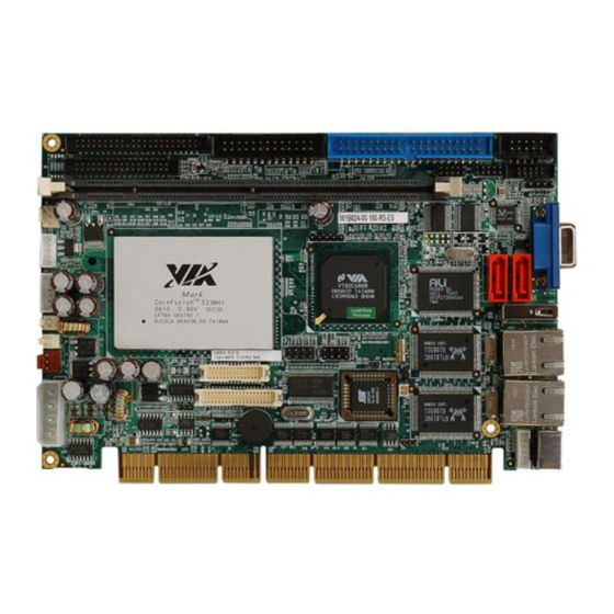
PCISA -6612 CPU Card 1.2 PCISA-6612 Overview Figure 1-1: PCISA-6612 Overview Page 18 IEI ® Technology, Corp. -
Page 19: Pcisa-6612 Connectors
PCISA -6612 CPU Card Figure 1-2: PCISA-6612 Solder Side Overview 1.2.1 PCISA-6612 Connectors The PCISA-6612 has the following connectors on-board: 1 x 184-pin DDR DIMM socket 1 x Audio connector 1 x Backplane to mainboard connector 1 x CompactFlash... - Page 20 PCISA -6612 CPU Card 2 x RS-232 serial port connectors 2 x USB 2.0 connectors The PCISA-6612 has the following external peripheral interface connectors: 2 x Ethernet connectors 1 x PS/2 keyboard/mouse connector 1 x USB connector 1 x VGA connector...
-
Page 21: Technical Specifications
PCISA -6612 CPU Card 1.2.2 Technical Specifications PCISA-6612 technical specifications are listed in Table 1-2. Detailed descriptions of each specification can be found in Chapter 2. SPECIFICATION DESCRIPTION ® ® CPUs Supported Intel Pentium M Socket 479 / Celeron® M up to 2.26GHz... -
Page 22: Table 1-2: Technical Specifications
PCISA -6612 CPU Card SPECIFICATION DESCRIPTION Serial ATA (SATA) Four SATA channels with 150Mb/s transfer rates Supports RAID 0, 1 Floppy Disk Drive (FDD) Supports one FDD ® CompactFlash (CF) II USB Interfaces Support five USB 2.0 devices Serial Ports Two RS-232 COM ports Audio Interface Realtek ALC655 with AC `97 codec... -
Page 23: Detailed Specifications
PCISA -6612 CPU Card Chapter Detailed Specifications Page 23... -
Page 24: Overview
This chapter describes the specifications and on-board features of the PCISA-6612 CPU card in detail. 2.2 Compatible IEI Backplanes The PCISA-6612 CPU card is compatible with all IEI PCI backplanes. For more information on these backplanes, visit the IEI website or contact your CPU card reseller or vendor. -
Page 25: Table 2-2: Supported Intel ® Pentium ® M Cpus
PCISA -6612 CPU Card overflow" attacks when combined with a supporting operating system. ® Intel® Mobile Voltage Positioning (Intel MVP IV) dynamically lowers voltage based on processor activity to lower thermal design power. Micro FCPGA & FCBGA packaging technology optimized for a range of thinner, lighter designs including <1”... -
Page 26: On-Board Chipsets
PCISA -6612 CPU Card ® ® Table 2-3 lists the Intel Celeron M processors supported by the PCISA-6612. Processor Execute Power Architecture Speed Number Cache Disable Bit Normal 90nm 1.50GHz 400MHz Normal 130nm 512KB 1.30GHz 400MHz ® ® Table 2-3: Supported Intel... -
Page 27: Sis966 Southbridge Chipset
PCISA -6612 CPU Card DRAM Controller DDR400/DDR333/DDR266 Support Supports Up to 2 un-buffered DIMMs DDR400 Supports Up to 3 un-buffered DIMMs DDR333/266 Up to 1GB per DIMM with 512Mb tech Dynamic Clock Enable (CKE) control placing the Memory into Suspend to DRAM state SiS MuTIOL®... -
Page 28: Data Flow
PCISA -6612 CPU Card 2.5.4 Data Flow Figure 2-1 shows the data flow between the system chipset, the CPU and other I/O interfaces that can connect to the PCISA-6612 CPU card. Figure 2-1: Data Flow Block Diagram Page 28 IEI ® Technology, Corp. -
Page 29: Graphics Support
PCISA -6612 CPU Card 2.6 Graphics Support The graphics features listed below are all integrated on the SiS661CX Northbridge chipset. AGP 3.5 and AGP 2.0 Compliant AGP 8X/4X Mode Support Fast Write Support Support 1.5V interface only DX9 S/W Compliant High performance 256Bit 3D/128Bit 2D Graphic Engine 2 pixel rendering pipelines and 4 texture units per cycle (2P4T) Up to 200 MHz ECLK... -
Page 30: Memory Support
1394 host controller) 2.9 GbE Ethernet ® The PCISA-6612 has two PCI-E GbE Ethernet ports controlled by BROADCOM BCM5787M on-board. The BCM5787M is a seventh generation 10/100/1000BASE-T Ethernet LAN controller solution for high performance network applications. The device combines a triple-speed IEEE 802.3 compliant Media Access Controller (MAC) with a triple-speed Ethernet transceiver, PCIe bus interface, and on-chip buffer memory in a single device. -
Page 31: Super I/O
PCISA -6612 CPU Card 2.10 Super I/O General Meet LPC Spec. 1.01 Supports LDRQ#(LPC DMA), SERIRQ (Serial IRQ) Integrated Hardware Monitor functions Compliant with Microsoft® PC2000/PC2001 Hardware Design Guide Supports DPM (Device Power Management), ACPI Programmable configuration settings Single 24 or 48 MHz clock input It is 3.3V level but 5V tolerance support Besides LPC function pins (Pin21 ~ Pin30) and H/W monitor analog pins (Pin95 ~ Pin110) - Page 32 PCISA -6612 CPU Card Fully programmable serial-interface characteristics: • 5, 6, 7 or 8-bit characters • Even, odd or no parity bit generation/detection • 1, 1.5 or 2 stop bits generation Internal diagnostic capabilities: • Loop-back controls for communications link fault isolation •...
- Page 33 PCISA -6612 CPU Card 8 Bit Timer/ Counter Supports binary and BCD arithmetic 6 MHz, 8 MHz, 12 MHz, or 16 MHz operating frequency Serial Flash ROM Interface Supports up to 8M bits flash ROM General Purpose I/O Ports 48 programmable general purpose I/O ports GPIO port 1 and 4 can not only serve as simple I/O ports but also watch dog timer output, Power LED output, Suspend LED output Functional in power down mode (GP24 ~ GP27, GPIO-3, GPIO-4,...
-
Page 34: Drive Interfaces
2 x IDE devices 1 x FDD 2.11.1 SATA Drives The PCISA-6612 supports four, first generation SATA drives with transfer rates of up to 150Mb/s. 2.11.2 IDE HDD Interfaces The PCISA-6612 system chipset IDE controller supports up to two HDDs with the... -
Page 35: Audio Codec
2.13 Audio Codec 2.13.1 Audio Codec Overview The PCISA-6612 has an integrated REALTEK ALC655 CODEC. The ALC655 CODEC is a 16-bit, full-duplex AC'97 Rev. 2.3 compatible six-channel audio CODEC designed for PC multimedia systems, including host/soft audio and AMR/CNR-based designs. -
Page 36: Real Time Clock
CPU, chipset, and battery voltage, +3.3V, +5V, and +12V CPU and board temperatures (by the corresponding embedded sensors) 2.16 BIOS The PCISA-6612 uses a licensed copy of AMI BIOS. The features of the flash BIOS used are listed below: SMIBIOS (DMI) compliant... -
Page 37: Operating Temperature And Temperature Control
CPU. 2.18 Power Consumption ® Table 2-4 shows the power consumption parameters for the PCISA-6612 when an Intel ® Pentium M 2.13G/2M/533 FSB CPU is running with a 1GB DDR 400MHz RAM module. -
Page 38: Optional Accessory Items
PCISA -6612 CPU Card 2.19.2 Optional Accessory Items The following are optional accessory items purchased separately. FDD cable LPT cable Page 38 IEI ® Technology, Corp. -
Page 39: Connectors And Jumpers
PCISA -6612 CPU Card Chapter Connectors and Jumpers Page 39... -
Page 40: Peripheral Interface Connectors
3.1 Peripheral Interface Connectors Section 3.1.1 shows peripheral interface connector locations. Section 3.1.2 lists all the peripheral interface connectors seen in Section 3.1.1. 3.1.1 PCISA-6612 Layout Figure 3-1 shows the on-board peripheral connectors and on-board jumpers. Figure 3-1: Connector and Jumper Locations Page 40 IEI ®... -
Page 41: Peripheral Interface Connectors
PCISA -6612 CPU Card 3.1.2 Peripheral Interface Connectors Table 3-1 shows a list of the peripheral interface connectors on the PCISA-6612. Detailed descriptions of these connectors can be found in Section 3.2. Connector Type Label Audio connector 8-pin header J_AUDIO1... -
Page 42: External Peripheral Interface Connectors
8-pin header USB01 USB23 Table 3-1: Peripheral Interface Connectors 3.1.3 External Peripheral Interface Connectors Table 3-2 lists the external peripheral interface connectors on the PCISA-6612. Detailed descriptions of these connectors can be found in Section 3.3. Connector Type Label Ethernet connectors... -
Page 43: On-Board Jumpers
Internal peripheral connectors are found on the CPU card and are only accessible when the CPU card is outside of the chassis. This section has complete descriptions of all the internal peripheral connectors on the PCISA-6612. 3.2.1 Audio Connector (8-pin) -
Page 44: Backplane To Mainboard Connector
PCISA -6612 CPU Card Figure 3-2: Audio Connector Location PIN NO. DESCRIPTION PIN NO. DESCRIPTION SYNC BITCLK SDOUT PCBEEP SDIN RST# +12V Table 3-4: Audio Connector Pinouts 3.2.2 Backplane to Mainboard Connector CN Label: ATXCTL1 CN Type: 3-pin wafer connector CN Location: See Figure 3-4 CN Pinouts:... -
Page 45: Compactflash ® Connector
PCISA -6612 CPU Card Figure 3-3: Backplane to Mainboard Connector Location PIN NO. DESCRIPTION PS_ON# 5VSB Table 3-5: Backplane to Mainboard Connector Pinouts ® 3.2.3 CompactFlash Connector CN Label: CF1 (solder side) 50-pin header (2x25) CN Type: CN Location: See Figure 3-4 CN Pinouts: See Table 3-6 Page 45... -
Page 46: Figure 3-4: Compactflash ® Connector Location
PCISA -6612 CPU Card ® Figure 3-4: CompactFlash Connector Location Page 46 IEI ® Technology, Corp. -
Page 47: Table 3-6: Compactflash ® Connector Pinouts
PCISA -6612 CPU Card PIN NO. DESCRIPTION PIN NO. DESCRIPTION CD1# CE2# VS1# IOR# IOW# CSEL# VS2# RESET# WAIT# INPACK# REG# BVD2 BVD1 IOCS16# CD2# GND2 ® Table 3-6: CompactFlash Connector Pinouts Page 47... -
Page 48: Cpu Fan Connector (+5V)
PCISA -6612 CPU Card 3.2.4 CPU Fan Connector (+5V) CN Label: CPU_FAN1 CN Type: 4-pin wafer CN Location: See Figure 3-5 CN Pinouts: See Table 3-7 The cooling fan connector provides a +12V, 500mA current to a system cooling fan. The connector has a "rotation"... -
Page 49: Digital Input/Output (Dio) Connector
PCISA -6612 CPU Card PIN NO. DESCRIPTION Rotation Signal +12V Sense Control Table 3-7: CPU Fan Connector Pinouts 3.2.5 Digital Input/Output (DIO) Connector CN Label: DIO1 CN Type: 10-pin header (2x5) CN Location: See Figure 3-6 CN Pinouts: See Table 3-8 The DIO connector is managed through a Super I/O chip. -
Page 50: Floppy Disk Connector
PCISA -6612 CPU Card PIN NO. DESCRIPTION PIN NO. DESCRIPTION Output 3 Output 2 Output 1 Output 0 Input 3 Input 2 Input 1 Input 0 Table 3-8: DIO Connector Connector Pinouts 3.2.6 Floppy Disk Connector CN Label: FDD1 CN Type: 34-pin box header CN Location: See Figure 3-7... -
Page 51: Front Panel Connector
PCISA -6612 CPU Card PIN NO. DESCRIPTION PIN NO. DESCRIPTION GROUND REDUCE WRITE GROUND GROUND GROUND INDEX# GROUND MOTOR ENABLE A# GROUND DRIVE SELECT B# GROUND DRIVE SELECT A# GROUND MOTOR ENABLE B# GROUND DIRECTION# GROUND STEP# GROUND WRITE DATA# GROUND WRITE GATE# GROUND... -
Page 52: Ide Connector
PCISA -6612 CPU Card Power button Power LED HDD LED Reset Figure 3-8: Front Panel Connector Locations FUNCTION DESCRIPTION FUNCTION DESCRIPTION Power PWRBTN- Power LED Button HDD LED Reset SYSRST- HDD LED- Table 3-10: Front Panel Connector Pinouts 3.2.8 IDE Connector CN Label: PIDE1 CN Type:... -
Page 53: Figure 3-9: Ide Device Connector Location
PCISA -6612 CPU Card One 40-pin IDE device connector on the PCISA-6612 CPU card supports connectivity to Ultra ATA/133 IDE devices with data transfer rates up to 133MB/s. Figure 3-9: IDE Device Connector Location DESCRIPTION DESCRIPTION RESET# GROUND DATA 7... -
Page 54: Ir Interface Connector
PCISA -6612 CPU Card DATA 5 DATA 10 DATA 4 DATA 11 DATA 3 DATA 12 DATA 2 DATA 13 DATA 1 DATA 14 DATA 0 DATA 15 GROUND IDE DRQ GROUND IOW# GROUND IOR# GROUND IDE CHRDY BALE – DEFAULT IDE DACK GROUND INTERRUPT... -
Page 55: Keyboard Connector
PCISA -6612 CPU Card Figure 3-10: IR Interface Connector Location PIN NO. DESCRIPTION IR-RX IR-TX Table 3-12: IR Interface Connector Pinouts 3.2.10 Keyboard Connector CN Label: CN Type: 5-pin wafer connector CN Location: See Figure 3-11 CN Pinouts: See Table 3-13 The keyboard connector can be connected to a standard PS/2 cable or PS/2 Y-cable to add keyboard functionality to the system. -
Page 56: Lcd Inverter Connector
CN Type: 5-pin wafer (1x5) CN Location: See Figure 3-12 CN Pinouts: See Table 3-14 The LCD inverter connector provides the backlight on the LCD panel connected to the PCISA-6612 with +12V of power. Page 56 IEI ® Technology, Corp. -
Page 57: Lcd Lvds Interface Connector
PCISA -6612 CPU Card Figure 3-12: LCD Inverter Connector Pinout Location PIN NO. DESCRIPTION BRIGHTNESS GROUND +12V GROUND BACKLIGHT ENABLE Table 3-14: LCD Inverter Connector Pinouts 3.2.12 LCD LVDS Interface Connector CN Label: LVDS1 30-pin crimp connector CN Type: CN Location: See Figure 3-13 CN Pinouts: See Table 3-15... -
Page 58: Figure 3-13: Tft Lcd Lvds Connector Location
PCISA -6612 CPU Card Figure 3-13: TFT LCD LVDS Connector Location PIN NO. DESCRIPTION PIN NO. DESCRIPTION LVDSA_Y0- LVDSA_Y0+ LVDSA_Y1- LVDSA_Y1+ LVDSA_Y2- LVDSA_Y2+ LVDSA_CLK- LVDSA_CLK+ Page 58 IEI ® Technology, Corp. -
Page 59: Parallel Port Connector
PCISA -6612 CPU Card LVDSA_Y3- LVDSA_Y3+ LVDSB_Y0- LVDSB_Y0+ LVDSB_Y1- LVDSB_Y1+ LVDSB_Y2- LVDSB_Y2+ LVDSB_CLK- LVDSB_CLK+ LVDSB_Y3- LVDSB_Y3+ LVDS_VCC LVDS_VCC LVDS_VCC LVDS_VCC Table 3-15: TFT LCD LVDS Connector Pinouts 3.2.13 Parallel Port Connector CN Label: LPT1 CN Type: 26-pin box header CN Location: See Figure 3-14 CN Pinouts: See Table 3-16... -
Page 60: Figure 3-14: Parallel Port Connector Location
PCISA -6612 CPU Card Figure 3-14: Parallel Port Connector Location PIN NO. DESCRIPTION PIN NO. DESCRIPTION STROBE# AUTO FORM FEED # DATA0 ERROR# DATA1 INITIALIZE# DATA2 PRINTER SELECT LN# DATA3 DATA4 DATA5 DATA6 DATA7 ACKNOWLEDGE# BUSY PAPER EMPTY PRINTER SELECT Table 3-16: Parallel Port Connector Pinouts Page 60 IEI ®... -
Page 61: Serial Port Connectors
PCISA -6612 CPU Card 3.2.14 RS-232 Serial Port Connectors CN Label: COM1, COM 2 CN Type: 2 x 5-pin box header CN Location: See Figure 3-15 CN Pinouts: See Table 3-17 The COM1 and COM 2 serial port connector connects to RS-232 serial port devices. Figure 3-15: RS-232 Serial Port Connectors Locations Page 61... -
Page 62: Sata Drive Connectors
PCISA -6612 CPU Card DESCRIPTION DESCRIPTION DATA CARRIER DETECT (DCD) DATA SET READY (DSR) RECEIVE DATA (RXD) REQUEST TO SEND (RTS) TRANSMIT DATA (TXD) CLEAR TO SEND (CTS) DATA TERMINAL READY (DTR) RING INDICATOR (RI) GROUND (GND) Table 3-17: RS-232 Serial Port Connectors Pinouts 3.2.15 SATA Drive Connectors CN Label: SATA1, SATA2, SATA3, SATA4... -
Page 63: Figure 3-16: Sata Drive Connector Locations
PCISA -6612 CPU Card Figure 3-16: SATA Drive Connector Locations PIN NO. DESCRIPTION Table 3-18: SATA Drive Connector Pinouts Page 63... -
Page 64: Usb Connectors
PCISA -6612 CPU Card 3.2.16 USB Connectors CN Label: USB01, USB23 CN Type: 8-pin header (2x4) CN Location: See Figure 3-17 CN Pinouts: See Table 3-19 The 2 x 4-pin USB connectors provide connectivity to USB 2.0 ports. Each USB connector can support two USB devices. -
Page 65: External Peripheral Interface Connector Panel
PCISA -6612 CPU Card 3.3 External Peripheral Interface Connector Panel Figure 3-18 shows the PCISA-6612 external peripheral interface connector panel. The peripheral connectors are connected to external devices when the PCISA-6612 is installed in a chassis. The peripheral connectors on the panel are:... -
Page 66: Lan Connectors
CN Pinouts: See Table 3-20 The PCISA-6612 is equipped with two built-in GbE Ethernet controllers. The controllers can connect to the LAN through two RJ-45 LAN connectors. There are two LEDs on the connector indicating the status of LAN. The pin assignments are listed in the following table: PIN NO. -
Page 67: Mini-Din 6 Ps/2 Connector
CN Pinouts: See Table 3-22 The PCISA-6612 CPU card has a mini-DIN 6 PS/2 connector on the mounting bracket for easy connection to a PS/2 keyboard or PS/2 mouse. The card comes with a cable to convert the mini-DIN 6 PS/2 into two mini-DIN 6 PS/2 connectors for keyboard and mouse connection. -
Page 68: Usb Connector
CN Type: CN Location: See Figure 3-18 (labeled number 3) CN Pinouts: See Table 3-23 The PCISA-6612 has a one rear panel USB port. This port connects to both USB 2.0 and USB 1.1 devices. PIN NO. DESCRIPTION DATA- DATA+... -
Page 69: Vga Connector
PCISA -6612 CPU Card 3.3.4 VGA connector CN Label: VGA1 CN Type: HD-D-sub 15 female connector CN Location: See Figure 3-18 (labeled number 4) CN Pinouts: See Table 3-24 A 15-pin VGA connector connects to standard displays. Figure 3-21: VGA Connector PIN NO. - Page 70 PCISA -6612 CPU Card THIS PAGE IS INTENTIONALLY LEFT BLANK Page 70 IEI ® Technology, Corp.
-
Page 71: Installation
PCISA -6612 CPU Card Chapter Installation Page 71... -
Page 72: Anti-Static Precautions
4.1 Anti-static Precautions Electrostatic discharge (ESD) can cause serious damage to electronic components, including the PCISA-6612. (Dry climates are especially susceptible to ESD.) It is therefore critical that whenever the PCISA-6612 (or any other electrical component) is handled, the following anti-static precautions are strictly adhered to. -
Page 73: Unpacking
PCB circuit, connector pins, or its components. 4.3 Unpacking NOTE: If any of the items listed below are missing when the PCISA-6612 is unpacked, do not proceed with the installation. Contact the reseller or vendor CPU card was purchased from. 4.3.1 Unpacking Precautions Some components on PCISA-6612 are very sensitive to static electricity and can be damaged by a sudden rush of power. -
Page 74: Checklist
1 x Utility CD 1 x QIG (quick installation guide) If one or more of these items are missing, contact the reseller or vendor PCISA-6612 was purchased from and do not proceed any further with the installation. 4.4 PCISA-6612 CPU Card Installation... -
Page 75: Preinstalled Component
CPU and DIMM modules. 4.4.1 Preinstalled Component The component listed below is preinstalled on the PCISA-6612. 4.4.2 Components to Install To install the PCISA-6612, the following components must be installed or connected to the PCISA-6612: DIMM module Peripheral devices 4.4.3 DIMM Module Installation... -
Page 76: Figure 4-1: Dimm Module Installation
PCISA -6612 CPU Card 4.4.3.2 DIMM Module Installation The PCISA-6612 CPU card has one DDR SDRAM DIMM socket. To install a DIMM module, follow the instructions below and refer to Figure 4-1. Step 1: Pull the two white handles on either side of the DIMM socket down. -
Page 77: Peripheral Device Connection
PCISA -6612 CPU Card 4.4.4 Peripheral Device Connection Cables provided by IEI that connect peripheral devices to the board are listed in Table 4-1. Cables not included in the kit must be separately purchased. Quantity Type ATA 66/100 HDD cable Dual RS-232 cables KB/MS Y cable SATA cables... -
Page 78: Figure 4-2: Connection Of Ide Connector
4.4.4.2 SATA Drive Connection The PCISA-6612 has two on-board 150Mb/s SATA drive connectors. The PCISA-6612 is shipped with two SATA drive cables and one SATA drive power cable. To connect the SATA drives to the connectors, follow the steps below. -
Page 79: Figure 4-3: Sata Drive Cable Connection
PCISA -6612 CPU Card Step 1: Locate the SATA drive connector on the board. Step 2: Press the clip on the connector at the end of the SATA cable and insert the cable connector into the on-board SATA drive connector (Figure 4-3). Figure 4-3: SATA Drive Cable Connection Step 3: Connect the connector on the other end of the cable to the connector at the back... -
Page 80: Figure 4-4: Sata Drive Connection
PCISA -6612 CPU Card Figure 4-4: SATA Drive Connection 4.4.4.3 LCD Backlight Installation To connect an LCD backlight (inverter) to the CPU card, follow the instruction below. Step 1: Connect the 5-pin connector end of the LCD backlight cable to the INVERTER1 header on the CPU card. -
Page 81: Figure 4-5: Compactflash ® Card Installation
To install a CFII card, follow the instructions below. Step 1: Turn the PCISA-6612 over so that the CFII card socket is facing up. Step 2: Carefully insert the CFII card into the socket, making sure the socket pins are properly inserted into the socket (Figure 4-5) ®... -
Page 82: Figure 4-6: Dual Rs-232 Cable Installation
Step 0: 4.4.4.7 USB 2.0 Cable Connection The PCISA-6612 is shipped with a dual USB cable. The dual USB cable consists of two connectors attached to two independent cables. Each cable is then attached to a USB port connector that is mounted on a bracket. To install the USB cable, follow the steps below. -
Page 83: Jumper Settings
USB module and the chassis. Step 2: Insert the two 4-pin connectors from the module into the USB pin headers on the PCISA-6612. (Figure 4-7) Figure 4-7: USB Cable Installation 4.5 Jumper Settings Page 83... - Page 84 OPEN a jumper means removing the plastic clip from a jumper. Before the PCISA-6612 is installed in the system, the jumpers must be set in accordance with the desired configuration. The PCISA-6612 CPU card has three on-board jumpers.
-
Page 85: Clear Cmos Jumper
Clear CMOS setup J_CMOS1 3-pin header LVDS Voltage Selection J_VLVDS1 3-pin header VCCA Voltage Selection J_VCCA1 2-pin header Figure 4-8 shows the PCISA-6612 jumper locations. Figure 4-8: Jumper Locations 4.5.1 Clear CMOS Jumper Jumper Label: J_CMOS1 3-pin header Jumper Type: Jumper Settings:... -
Page 86: Lvds Voltage Selection
PCISA -6612 CPU Card If the PCISA-6612 fails to boot due to improper BIOS settings, use this connector to clear the CMOS data and reset the system BIOS information. To do this, use the jumper cap to close pins 2 and 3 for a few seconds then reinstall the jumper clip back to pins 1 and 2. -
Page 87: Vcca Voltage Selection
PCISA -6612 CPU Card Jumper Label: J_VLVDS1 3-pin header Jumper Type: Jumper Settings: See Table 4-3 Jumper Location: See Figure 4-8 The J_LVDS1 jumper allows the LVDS screen voltage to be set. J_LVDS1 DESCRIPTION +3.3V LVDS Short 2-3 +5V LVDS Table 4-3: LVDS Voltage Selection Jumper Settings 4.5.3 VCCA Voltage Selection Jumper Label:... -
Page 88: Inserting The Cpu Card
After the DIMM module has been installed and after the internal peripheral connectors have been connected to the peripheral devices and the jumpers have been configured, the PCISA-6612 can be inserted onto a PCISA slot on the backplane. To insert the CPU card to a backplane, follow the instructions below. -
Page 89: Vga Port Installation
PCISA -6612 CPU Card 4.7.4 VGA Port Installation The cable used to connect the motherboard to a VGA port is a 10-pin header to female HD-D-sub 15 connector. To connect a VGA port to the motherboard, follow the instructions below. Step 1: Connect a standard male HD-D-sub 15 connector end to the VGA connector on the rear panel. - Page 90 PCISA -6612 CPU Card THIS PAGE IS INTENTIONALLY LEFT BLANK Page 90 IEI ® Technology, Corp.
-
Page 91: Bios Settings
PCISA -6612 CPU Card Chapter BIOS Settings Page 91... -
Page 92: Introduction
PCISA -6612 CPU Card 5.1 Introduction A licensed copy of AMI BIOS is preprogrammed into the ROM BIOS. The BIOS setup program allows users to modify the basic system configuration. This chapter describes how to access the BIOS setup program and the configuration options that may be changed. -
Page 93: Getting Help
PCISA -6612 CPU Card F2 /F3 key Change color from total 16 colors. F2 to select color forward. F10 key Save all the CMOS changes, only for Main Menu Table 5-1: BIOS Navigation Keys 5.1.3 Getting Help When F1 is pressed a small help window describing the appropriate keys to use and the possible selections for the highlighted item appears. -
Page 94: Main
PCISA -6612 CPU Card 5.2 Main When the BIOS Setup program is entered, the Main menu (BIOS Menu 1) appears. The Main menu gives an overview of the basic system information. BIOS Menu 1: Main System Overview The System Overview lists a brief summary of different system components. The fields in System Overview cannot be changed. -
Page 95: Advanced
PCISA -6612 CPU Card Type: Names the currently installed processor Speed: Lists the processor speed Count: The number of CPUs on the motherboard System Memory: Displays the auto-detected system memory. Size: Lists memory size The System Overview field also has two user configurable fields: System Time [xx:xx:xx]: The system time is set here. -
Page 96: Cpu Configuration
PCISA -6612 CPU Card BIOS Menu 2: Advanced 5.3.1 CPU Configuration The CPU Configuration menu (BIOS Menu 3) shows detailed CPU specifications and CPU configuration options. Page 96 IEI ® Technology, Corp. -
Page 97: Bios Menu 3: Cpu Configuration
PCISA -6612 CPU Card BIOS Menu 3: CPU Configuration The CPU Configuration menu (BIOS Menu 3) lists the following CPU details: Manufacturer: Lists the name of the CPU manufacturer Brand String: Lists the brand name of the CPU being used Frequency: Lists the CPU processing speed FSB Speed: Lists the FSB speed Cache L1: Lists the CPU L1 cache size... - Page 98 PCISA -6612 CPU Card Execute Bit Disable [Enabled] Use the Execute Bit Disable BIOS function to protect the system from buffer overflow attacks. Disabled Code can be executed in any memory area. Enabled Code execution in data-only memory pages is EFAULT prohibited.
-
Page 99: Ide Configuration
PCISA -6612 CPU Card EMI not reduced Disabled EFAULT Enabled EMI reduced 5.3.2 IDE Configuration The IDE Configuration menu (BIOS Menu 4) allows changes to the configurations for the IDE devices installed in the system. BIOS Menu 4: IDE Configuration Page 99... - Page 100 PCISA -6612 CPU Card OnBoard PCI IDE Controller [Both] Use the OnBoard PCI IDE Controller BIOS option to specify the IDE channels used by the on-board PCI IDE controller. The following configuration options are available. Disabled Prevents the system from using the on-board IDE controller Primary Only allows the system to detect the Primary IDE...
- Page 101 PCISA -6612 CPU Card Primary IDE Master Primary IDE Slave Secondary IDE Master Secondary IDE Slave Third IDE Master Third IDE Slave Fourth IDE Master Fourth IDE Slave The IDE Configuration menu (BIOS Menu 4) allows changes to the configurations for the IDE devices installed in the system.
- Page 102 PCISA -6612 CPU Card The best setting to use if the on-board IDE controllers are set to a specific IDE disk drive in the AMIBIOS is “0 seconds” and a large majority of ultra ATA hard disk drives can be detected well within “5 seconds”.
-
Page 103: Bios Menu 5: Ide Master And Ide Slave Configuration
PCISA -6612 CPU Card BIOS Menu 5: IDE Master and IDE Slave Configuration Auto-Detected Drive Parameters The “grayed-out” items in the left frame are IDE disk drive parameters automatically detected from the firmware of the selected IDE disk drive. The drive parameters are listed as follows: Device: Lists the device type (e.g. - Page 104 PCISA -6612 CPU Card PIO Mode: Indicates the PIO mode of the installed device. Async DMA: Indicates the highest Asynchronous DMA Mode that is supported. Ultra DMA: Indicates the highest Synchronous DMA Mode that is supported. S.M.A.R.T.: Indicates whether or not the Self-Monitoring Analysis and Reporting Technology protocol is supported.
- Page 105 PCISA -6612 CPU Card Disabled BIOS is prevented from using the LBA mode control on the specified channel. BIOS auto detects the LBA mode control on the specified Auto EFAULT Mode channel. Block (Multi Sector Transfer) [Auto Mode] Use the Block (Multi Sector Transfer) to disable or enable BIOS to auto detect if the device supports multi-sector transfers.
- Page 106 PCISA -6612 CPU Card PIO mode 2 selected with a maximum transfer rate of 8.3MBps PIO mode 3 selected with a maximum transfer rate of 11.1MBps PIO mode 4 selected with a maximum transfer rate of 16.6MBps (This setting generally works with all hard disk drives manufactured after 1999.
-
Page 107: Floppy Configuration
PCISA -6612 CPU Card 5.3.3 Floppy Configuration Use the Floppy Configuration menu (BIOS Menu 6) to set or change the configurations for floppy disk drives. BIOS Menu 6: Floppy Configuration Floppy A [1.44 MB 3½”] The Floppy A configuration option determines the types of the floppy drive installed in the system. -
Page 108: Super Io Configuration
PCISA -6612 CPU Card Disabled 360 KB 5¼” 1.2 MB 5¼” 720 KB 3 ½” 1.44 MB 3½” EFAULT 2.88 MB 3½” 5.3.4 Super IO Configuration The Super IO Configuration menu (BIOS Menu 7) sets or changes the configurations for the FDD controllers, parallel ports and serial ports. - Page 109 PCISA -6612 CPU Card On Board Floppy Controller [Enabled] Use the Onboard Floppy Controller to enable or disable the floppy driver controller. Disabled BIOS disables the floppy controller Enabled BIOS enables the floppy controller EFAULT Serial Port1 Address [3F8/IRQ4] Use the Serial Port1 Address option to select the Serial Port 1 base address. No base address is assigned to Serial Port 1 Disabled 3F8/IRQ4...
- Page 110 PCISA -6612 CPU Card Serial Port2 Mode [Normal] Use the Serial Port2 Mode option to select the Serial Port2 operational mode. Normal Serial Port 2 mode is normal EFAULT IrDA Serial Port 2 mode is IrDA ASK IR Serial Port 2 mode is ASK IR Parallel Port Address [378] Use the Parallel Port Address option to select the parallel port base address.
- Page 111 PCISA -6612 CPU Card The parallel port operates in the enhanced parallel port mode (EPP). The EPP mode supports bi-directional communication between the system and the parallel port device and the transmission rates between the two are much faster than the Normal mode.
-
Page 112: Hardware Health Configuration
PCISA -6612 CPU Card 5.3.5 Hardware Health Configuration The Hardware Health Configuration menu (BIOS Menu 8) shows the operating temperature, fan speeds and system voltages. BIOS Menu 8: Hardware Health Configuration The following system parameters and values are shown. The system parameters that are monitored are: System Temperatures: The following system temperatures are monitored System Temperature... -
Page 113: Acpi Configuration
PCISA -6612 CPU Card Voltages: The following system voltages are monitored. Vcore +3.3Vin +5Vin +12Vin 5.3.6 ACPI Configuration The ACPI Configuration menu (BIOS Menu 9) configures the Advanced Configuration and Power Interface (ACPI) and Power Management (APM) options. BIOS Menu 9: ACPI Configuration Page 113... - Page 114 PCISA -6612 CPU Card ACPI Aware O/S [Yes] Use the ACPI Aware O/S option to enable the system to configure ACPI power saving options. ACPI can only be implemented if the system OS complies with the ACPI standard. Windows 98, Windows 2000, and Windows XP all comply with ACPI. Disables the ACPI support for the OS.
-
Page 115: Bios Menu 10: Advanced Acpi Configuration
PCISA -6612 CPU Card 5.3.6.1 Advanced ACPI Configuration Use the Advanced ACPI Configuration menu (BIOS Menu 10) to select the ACPI state when the system is suspended. BIOS Menu 10: Advanced ACPI Configuration Page 115... - Page 116 PCISA -6612 CPU Card ACPI Version Features [ACPI v2.0] Use the ACPI Version Features option to enable the ACPI (Advanced Configuration and Power Interface) features. By enabling this feature the system RSDP (Root System Description Pointer) is able to obtain physical addresses for other 64-bit fixed system description tables.
-
Page 117: Mps Configuration
PCISA -6612 CPU Card 5.3.7 MPS Configuration The MPS Configuration menu (BIOS Menu 11) configures the multi-processor table. BIOS Menu 11: MPS Configuration MPS Revision [1.4] The Multiprocessor Specification (MPS) for OS specifies the MPS version to be used. MPS version 1.1 is used MPS version 1.4 is used EFAULT Page 117... -
Page 118: Usb Configuration
PCISA -6612 CPU Card 5.3.8 USB Configuration The USB Configuration menu (BIOS Menu 12) gives USB configuration information and configures some USB features. BIOS Menu 12: USB Configuration Onboard SiS USB1.1 DEVICE [Enabled] Use the Onboard SiS USB1.1 DEVICE BIOS option to enable or disable the on-board SiS USB1.1 controller. - Page 119 PCISA -6612 CPU Card Use the Onboard SiS USB2.0 DEVICE option to enable or disable the on-board SiS USB2.0 controller. If disabled, USB2.0 devices cannot be used. Disabled USB 2.0 interface is disabled and cannot be used. Enabled USB 2.0 interface is enabled and can be used. EFAULT Legacy USB Support [Enabled] Use the Legacy USB Support BIOS option to enable USB mouse and USB keyboard...
- Page 120 PCISA -6612 CPU Card BIOS EHCI Handoff [Enabled] Use the BIOS EHCI Handoff option for systems running OSes that do not have EHCI hand-off support. The EHCI ownership change is managed by the EHCI driver. Disabled Systems with OSes that do not support EHCI can use the EHCI handoff functionality.
-
Page 121: Menu 13: Usb Mass Storage Device Configuration
PCISA -6612 CPU Card 5.3.8.1 USB Mass Storage Device Configuration Use the USB Mass Storage Device Configuration menu (BIOS Menu 13) to configure USB mass storage class devices. BIOS Menu 13: USB Mass Storage Device Configuration USB Mass Storage Reset Delay [20 Sec] Use the USB Mass Storage Reset Delay option to set the number of seconds POST waits for the USB mass storage device after the start unit command. - Page 122 PCISA -6612 CPU Card POST waits 10 seconds for the USB mass storage 10 Sec device after the start unit command. 20 Sec POST waits 20 seconds for the USB mass storage EFAULT device after the start unit command. 30 Sec POST waits 30 seconds for the USB mass storage device after the start unit command.
-
Page 123: Pci/Pnp
PCISA -6612 CPU Card Auto BIOS auto-detects the current USB. EFAULT Floppy The USB device will be emulated as a floppy drive. The device can be either A: or B: responding to INT13h calls that return DL = 0 or DL = 1 respectively. - Page 124 PCISA -6612 CPU Card Page 124 IEI ® Technology, Corp.
-
Page 125: Bios Menu 14: Pci/Pnp Configuration
PCISA -6612 CPU Card BIOS Menu 14: PCI/PnP Configuration Clear NVRAM [No] Use the Clear NVRAM option to specify if the NVRAM (Non-Volatile RAM) is cleared when the power is turned off. System does not clear NVRAM during system boot EFAULT System clears NVRAM during system boot Plug &... - Page 126 PCISA -6612 CPU Card If the operating system does not meet the Plug and Play EFAULT specifications, this option allows the BIOS to configure all the devices in the system. This setting allows the operating system to change the interrupt, I/O, and DMA settings. Set this option if the system is running Plug and Play aware operating systems.
- Page 127 PCISA -6612 CPU Card Palette Snooping [Disabled] Use the Palette Snooping option to enable or disable the palette snooping function. Disabled Unless the VGA card manufacturer requires palette EFAULT snooping to be enabled, this option should be disabled. Enabled PCI devices are informed that an ISA based Graphics device is installed in the system so the ISA based Graphics card functions correctly.
- Page 128 PCISA -6612 CPU Card PCI Slot 2 PCI Slot 2 is selected as the location of the OffBoard PCI IDE adapter card. Only select this slot if the adapter card is installed in PCI Slot 2. PCI Slot 3 PCI Slot 3 is selected as the location of the OffBoard PCI IDE adapter card.
- Page 129 PCISA -6612 CPU Card IRQ7 IRQ9 IRQ10 IRQ 11 IRQ 14 IRQ 15 DMA Channel# [Available] Use the DMA Channel# option to assign a specific DMA channel to a particular PCI/PnP device. Available The specified DMA is available to be used by EFAULT PCI/PnP devices Reserved...
-
Page 130: Boot
PCISA -6612 CPU Card No memory block reserved for legacy ISA devices Disabled EFAULT 16KB reserved for legacy ISA devices 32KB reserved for legacy ISA devices 54KB reserved for legacy ISA devices 5.5 Boot The Boot menu (BIOS Menu 15) configures system boot options. BIOS Menu 15: Boot Page 130 IEI ®... -
Page 131: Boot Settings Configuration
PCISA -6612 CPU Card 5.5.1 Boot Settings Configuration The Boot Settings Configuration menu (BIOS Menu 16) configures advanced system boot options. BIOS Menu 16: Boot Settings Configuration Quick Boot [Enabled] Use the Quick Boot BIOS option to make the computer speed up the boot process. Disabled No POST procedures are skipped Enabled... - Page 132 PCISA -6612 CPU Card Quiet Boot [Disabled] Use the Quiet Boot BIOS option to select the screen display when the system boots. Disabled Normal POST messages displayed EFAULT Enabled OEM Logo displayed instead of POST messages AddOn ROM Display Mode [Force BIOS] Use the AddOn ROM Display Mode option to allow add-on ROM (read-only memory) messages to be displayed.
- Page 133 PCISA -6612 CPU Card PS/2 Mouse Support [Auto Mode] Use the PS/2 Mouse Support option adjusts PS/2 mouse support capabilities. Disabled PS/2 mouse support is disabled and prevented from using system resources. Allows the system to use a PS/2 mouse. Enabled Auto Mode The system auto-adjusts PS/2 mouse support.
-
Page 134: Boot Device Priority
PCISA -6612 CPU Card No message displayed during POST Disabled Enabled Displays “Press DEL to run Setup” message in EFAULT POST Interrupt 19 Capture [Disabled] Use the Interrupt 19 Capture option to allow optional ROMs such as network controllers to trap BIOS interrupt 19. Disabled Does not allow optional ROM to trap interrupt 19 EFAULT... -
Page 135: Hard Disk Drives
PCISA -6612 CPU Card BIOS Menu 17: Boot Device Priority Settings 5.5.3 Hard Disk Drives The Hard Disk Drives menu (BIOS Menu 18) is similar to the Removable Drives BIOS Menu 19 and it specifies the boot sequence of the available HDDs. When the menu is opened, the HDDs connected to the system are listed as shown below: 1st Drive [HDD: PM-(part number)]... -
Page 136: Bios Menu 18: Hard Disk Drives
PCISA -6612 CPU Card BIOS Menu 18: Hard Disk Drives NOTE: Only the drives connected to the system are shown. For example, if only two HDDs are connected only “1st Drive” and “2nd Drive” are listed. The boot sequence from the available devices is selected. If the “1st Drive” option is selected a list of available HDDs is shown. -
Page 137: Removable Drives
PCISA -6612 CPU Card 5.5.4 Removable Drives The Removable Drives menu (BIOS Menu 19) specifies the boot sequence of the available FDDs. When the menu is opened, the FDDs connected to the system are listed as shown below: 1st Drive [1st FLOPPY DRIVE] 2nd Drive [2nd FLOPPY DRIVE]... -
Page 138: Cd/Dvd Drives
PCISA -6612 CPU Card BIOS Menu 19: Removable Drives 5.5.5 CD/DVD Drives The CD/DVD Drives menu (BIOS Menu 20) is similar to the Removable Drives BIOS Menu 19 and it specifies the boot sequence of the available CD/DVD drives. When the menu is opened, the CD drives and DVD drives connected to the system are listed as shown below: 1st Drive... -
Page 139: Bios Menu 20: Cd/Dvd Drives
PCISA -6612 CPU Card BIOS Menu 20: CD/DVD Drives NOTE: Only the drives connected to the system are shown. For example, if only two CDs or DVDs are connected only “1st Drive” and “2nd Drive” are listed. The boot sequence from the available devices is selected. If the “1st Drive” option is selected a list of available CD/DVD drives is shown. -
Page 140: Security
PCISA -6612 CPU Card 5.6 Security The Security menu (BIOS Menu 21) allows system security settings including passwords to be configured. BIOS Menu 21: Security Change Supervisor Password Use the Change Supervisor Password to set or change a supervisor password. The default for this option is Not Installed. -
Page 141: Chipset
PCISA -6612 CPU Card Change User Password Use the Change User Password to set or change a user password. The default for this option is Not Installed. If a user password must be installed, select this field and enter the password. -
Page 142: Northbridge Sis661Fx Configuration
PCISA -6612 CPU Card BIOS Menu 22: Chipset 5.7.1 Northbridge SIS661FX Configuration The Northbridge SIS661FX Configuration menu (BIOS Menu 23) allows the Northbridge chipset to be configured. Page 142 IEI ® Technology, Corp. -
Page 143: Bios Menu 23:Northbridge Chipset Configuration
PCISA -6612 CPU Card BIOS Menu 23:Northbridge Chipset Configuration Primary Graphics Adapter [PCI] Use the Primary Graphics Adapter option to select the graphics adapter the system uses. PCI graphics adapter is used EFAULT AGP graphics adapter is used DRAM CAS# Latency [By SPD] Use the CAS Latency Time configuration option to set the Column Address Strobe (CAS) delay time. - Page 144 PCISA -6612 CPU Card 2.5T Graphic Win Size [64MB] Use the Graphic Win Size option to select the size of the AGP aperture and the size of the GART (Graphics Address Relocation Table). The aperture is a portion on the PCI memory address range dedicated for use as AGP memory address space and the GART is a translation table that translates the AGP memory addresses into actual addresses.
-
Page 145: Southbridge Sis966 Configuration
PCISA -6612 CPU Card LCD Display Type [Full Screen] Use the LCD Display Type BIOS to specify the screen display type. Configuration options are listed below: Full Screen EFAULT Center Screen 5.7.2 Southbridge SiS966 Configuration The Southbridge SiS966 Configuration menu (BIOS Menu 24) allows the Southbridge chipset to be configured. - Page 146 PCISA -6612 CPU Card Enabled The on-board AC’97 automatically detected and enabled EFAULT Disabled The on-board AC’97 is disabled All PCI EXPRESS Controller [Enabled] Use the All PCI EXPRESS Controller option to enable or disable the Southbridge PCIE function. PCIe controllers enabled Enabled EFAULT Disabled...
-
Page 147: Power Management
PCISA -6612 CPU Card 5.8 Power Management The Power menu (BIOS Menu 25) allows the advanced power management options to be configured. BIOS Menu 25: Power Power Management/APM [Enabled] The Power Management/APM BIOS option allows access to the advanced power management features. - Page 148 PCISA -6612 CPU Card Disables the Advanced Power Management (APM) Disabled feature Enabled Enables the APM feature EFAULT Resume On PME# [Disabled] The Resume On PME# BIOS option to enable the system to be roused from a suspended or standby state when there is activity on the PCI PME (power management event) controller.
-
Page 149: Exit
PCISA -6612 CPU Card 5.9 Exit The Exit menu (BIOS Menu 26) loads default BIOS values, optimal failsafe values and to save configuration changes. BIOS Menu 26:Exit Save Changes and Exit If configuration changes are complete, select this option to save them and exit the BIOS menus. - Page 150 PCISA -6612 CPU Card Discard Changes If configuration changes are complete but do need to be saved but BIOS still needs to be run , select this option. Load Optimal Defaults This option loads optimal default values for each of the parameters on the Setup menus. F9 key can be used for this operation.
-
Page 151: Driver Installation
PCISA -6612 CPU Card Chapter Driver Installation Page 151... -
Page 152: Available Software Drivers
All drivers can be found on the CD that came with the motherboard. To install the drivers follow the instructions in the sections below. Insert the CD into the system that contains the PCISA-6612 motherboard. NOTE: If your system does not run the "autorun" program when the CD is inserted, click the Start button, select Run, then type X:\autorun.exe (replace X with the actual... -
Page 153: Sis Agp Driver Installation
PCISA -6612 CPU Card Step 3: From the SiS Solution Driver CD main menu (Figure 6-1), click PCISA-6612. Figure 6-1: SIS Solution CD Main Menu Step 4: A window appears listing the drivers available for installation. Step 5: Select any item from the list to view more information on the driver installation, or select Manual to navigate to the PCISA-6612 motherboard user manual. -
Page 154: Figure 6-2: Starting Install Shield Wizard Screen
PCISA -6612 CPU Card Step 3: The Starting Install Shield Wizard appears (Figure 6-2). Figure 6-2: Starting Install Shield Wizard Screen Step 4: The Preparing Setup window appears next (Figure 6-3). Figure 6-3: Preparing Setup Screen Step 5: The InstallShield window appears (Figure 6-4). Click N to continue the installation. -
Page 155: Figure 6-4: Install Shield Screen
PCISA -6612 CPU Card Figure 6-4: Install Shield Screen Step 6: The installation shield starts to extract and install files (Figure 6-5). Figure 6-5: Installing Screen Page 155... -
Page 156: Vga Driver Installation
PCISA -6612 CPU Card Step 7: After the driver installation process is complete, a confirmation screen appears (Figure 6-6). Figure 6-6: Restart the Computer Step 8: The confirmation screen offers the option of restarting the computer now or later. For the settings to take effect, the computer must be restarted. Click F INISH restart the computer.Step 0:... -
Page 157: Figure 6-7: Cd Vga Folder
PCISA -6612 CPU Card Figure 6-7: CD VGA Folder Step 3: Double-click the 3.76logo sub-folder to view the folder contents on the CD for the VGA driver (Figure 6-10). Figure 6-8: CD VGA\3.76logo Folder Step 4: Double-click the setup.exe file to begin the driver installation process. Page 157... -
Page 158: Figure 6-9: Starting Installshield Wizard Screen
PCISA -6612 CPU Card Step 5: The “Starting InstallShield Wizard” in Figure 6-11 appears. Figure 6-9: Starting InstallShield Wizard Screen Step 6: The “Preparing Setup” window in Figure 6-12 appears next. Figure 6-10: Preparing Setup Screen Page 158 IEI ® Technology, Corp. -
Page 159: Figure 6-11: Vga Utilities Welcome Screen
PCISA -6612 CPU Card Step 7: Then, the welcome screen shown in Figure 6-11 appears. Figure 6-11: VGA Utilities Welcome Screen Page 159... -
Page 160: Figure 6-12: Select Setup Installation Type
PCISA -6612 CPU Card Step 8: Select the setup type (Figure 6-12). Once the setup type is selected, click on the button in the setup type menu (Figure 6-12). Figure 6-12: Select Setup Installation Type Page 160 IEI ® Technology, Corp. -
Page 161: Figure 6-13: Select Folders To Copy Files
PCISA -6612 CPU Card Step 9: You are then prompted to select a folder to copy the files in (Figure 6-13). Once the setup type is selected, click on the N button. Figure 6-13: Select Folders to Copy Files Page 161... -
Page 162: Figure 6-14: Review Settings
PCISA -6612 CPU Card Step 10: Before the files are copied, you can review you selected settings (Figure 6-14). Once you have completed reviewing your settings, click on the N button. Figure 6-14: Review Settings Step 11: The driver installation will then start. Page 162 IEI ®... -
Page 163: Figure 6-15: Read Readme File
PCISA -6612 CPU Card Step 12: Once the installation is complete, you will be prompted to read the Read Me file (Figure 6-15). Select Y or N Figure 6-15: Read ReadMe File Page 163... -
Page 164: Audio Driver Installation
PCISA -6612 CPU Card Step 13: Once you have completed reading the Read Me file or it you skip reading the Read Me file, you will be prompted to restart your computer. Select Y or N Step 0: Figure 6-16: Restart the Computer 6.4 Audio Driver Installation To install the audio driver, please follow the steps below. -
Page 165: Figure 6-17: Cd 4-Audio\Ac97\Windows Folder
PCISA -6612 CPU Card Figure 6-17: CD 4-Audio\AC97\Windows Folder Step 3: Double-click the Setup.exe file to begin the driver installation process. Step 4: Once you double click the Setup icon, the install shield wizard for the audio driver starts. See Figure 6-18. Figure 6-18: Audio Driver Install Shield Wizard Starting Step 5: The Realtek Audio Setup prepares the install shield to guide you through the... -
Page 166: Figure 6-19: Audio Driver Setup Preparation
PCISA -6612 CPU Card Figure 6-19: Audio Driver Setup Preparation Page 166 IEI ® Technology, Corp. -
Page 167: Figure 6-20: Audio Driver Welcome Screen
PCISA -6612 CPU Card Step 6: After the install shield is prepared, the welcome screen shown in Figure 6-20 appears. To continue the installation process, click the “N ” button. The install shield starts to configure the new software as shown in Figure 6-21. Figure 6-20: Audio Driver Welcome Screen Page 167... -
Page 168: Figure 6-21: Audio Driver Software Configuration
PCISA -6612 CPU Card Figure 6-21: Audio Driver Software Configuration Page 168 IEI ® Technology, Corp. -
Page 169: Figure 6-22: Audio Driver Digital Signal
PCISA -6612 CPU Card Step 7: At this stage the “Digital Signal Not Found” screen appears (Figure 6-22). To continue the installation process, click the “Y ” button. The installation notice shown below will appear. Figure 6-22: Audio Driver Digital Signal Page 169... -
Page 170: Figure 6-23: Audio Driver Installation Begins
PCISA -6612 CPU Card Step 8: After clicking the “Y ” button in Figure 6-22, the installation of the driver begins (Figure 6-23). Figure 6-23: Audio Driver Installation Begins Page 170 IEI ® Technology, Corp. -
Page 171: Figure 6-24: Audio Driver Installation Complete
PCISA -6612 CPU Card Step 9: After the driver installation process is complete, a confirmation screen shown in Figure 6-24 appears. Figure 6-24: Audio Driver Installation Complete Step 10: The confirmation screen shown in Figure 6-24 allows you to restart the computer immediately after the installation is complete or to restart the computer later. -
Page 172: Lan Driver Installation
PCISA -6612 CPU Card 6.5 LAN Driver Installation To install the Broadcom LAN driver, please follow the steps below. Step 1: Open Windows Control Panel (Figure 6-25). Figure 6-25: Access Windows Control Panel Page 172 IEI ® Technology, Corp. -
Page 173: Figure 6-26: Double Click The System Icon
PCISA -6612 CPU Card Step 2: Double click the System icon (Figure 6-26). Figure 6-26: Double Click the System Icon Step 3: Double click the Device Manager tab (Figure 6-27). Figure 6-27: Double Click the Device Manager Tab Page 173... -
Page 174: Figure 6-28: Device Manager List
PCISA -6612 CPU Card Step 4: A list of system hardware devices appears (Figure 6-28). Figure 6-28: Device Manager List Step 5: Double click the listed device that has question marks next to it. (This means Windows does not recognize the device). Page 174 IEI ®... -
Page 175: Figure 6-29: Search For Suitable Driver
PCISA -6612 CPU Card Step 6: The Device Driver Wizard appears (Figure 6-29). Click N to continue. Figure 6-29: Search for Suitable Driver Page 175... -
Page 176: Figure 6-30: Locate Driver Files
PCISA -6612 CPU Card Step 7: Select “Specify a Location” in the Locate Driver Files window (Figure 6-30). Click N to continue. Figure 6-30: Locate Driver Files Page 176 IEI ® Technology, Corp. -
Page 177: Sis Ide Driver Installation
PCISA -6612 CPU Card Step 8: Select the proper OS folder under the “X:\5-LAN\BROADCOM BCM57xx Drivers” directory (Figure 6-31) in the location browsing window, where “X:\” is the system CD drive. Figure 6-31: Location Browsing Window Step 9: Click OK to continue. A driver files location menu window appears. Click N continue. -
Page 178: Figure 6-32: Select A Language
PCISA -6612 CPU Card Figure 6-32: Select a Language Step 3: The driver Welcome screen appears (Figure 6-33). Click N to continue the installation. Figure 6-33: Welcome Screen Page 178 IEI ® Technology, Corp. -
Page 179: Figure 6-34: Select Components
PCISA -6612 CPU Card Step 4: The Select Components screen appears (Figure 6-34). Select the appropriate component and click N to continue the installation. Figure 6-34: Select Components Step 5: The driver installation begins (Figure 6-35) Figure 6-35: Chipset Driver Installation Page 179... -
Page 180: Sis Sata Raid Utility Installation
PCISA -6612 CPU Card Step 6: The confirmation screen appears and offers the option of restarting the computer now or later. For the settings to take effect, the computer must be restarted. Click F to restart the computer.Step 0: INISH 6.7 SiS SATA RAID Utility Installation NOTE: The SATA RAID driver has to be installed in the SATA RAID mode. -
Page 181: Figure 6-37: Starting Install Shield Wizard
PCISA -6612 CPU Card Step 4: The “Starting InstallShield Wizard” in Figure 6-39 appears. Figure 6-37: Starting Install Shield Wizard Step 5: The Preparing Setup window appears next (Figure 6-38). Figure 6-38: Preparing Setup Page 181... -
Page 182: Figure 6-39: Install Shield
PCISA -6612 CPU Card Step 6: The InstallShield window appears next (Figure 6-39). Figure 6-39: Install Shield Page 182 IEI ® Technology, Corp. -
Page 183: Figure 6-40: License Agreement
PCISA -6612 CPU Card Step 7: Click N and a License Agreement screen appears (Figure 6-40). Read the license agreement. Figure 6-40: License Agreement Step 8: To accept the terms and conditions stipulated in the license agreement, click Page 183... -
Page 184: Figure 6-41: Install Application Directory
PCISA -6612 CPU Card Step 9: The Install Application Directory window appears (Figure 6-41). Click to manually select a destination folder for the program, or click N HANGE accept the default directory and continue the installation. Figure 6-41: Install Application Directory Page 184 IEI ®... -
Page 185: Figure 6-42: Select Needed Components
PCISA -6612 CPU Card Step 10: The Select Needed Components window appears (Figure 6-42). Figure 6-42: Select Needed Components Page 185... -
Page 186: Figure 6-43: Ready To Install
PCISA -6612 CPU Card Step 11: Select the necessary components by clicking the checkboxes and click N continue. Step 12: The Ready to Install window appears (Figure 6-43). Figure 6-43: Ready to Install Page 186 IEI ® Technology, Corp. -
Page 187: Figure 6-44: Setup Status
PCISA -6612 CPU Card Step 13: Click I and the install shield begins to extract and install the files (Figure NSTALL 6-44). Figure 6-44: Setup Status Page 187... -
Page 188: Figure 6-45: Restart The Computer
PCISA -6612 CPU Card Step 14: After the driver installation process is complete, a confirmation screen appears (Figure 6-45). Figure 6-45: Restart the Computer Step 15: The confirmation screen offers the option of restarting the computer now or later. For the settings to take effect, the computer must be restarted. Click F INISH restart the computer.Step 0:... - Page 189 PCISA -6612 CPU Card Appendix BIOS Configuration Options Page 189...
- Page 190 PCISA -6612 CPU Card A.1 BIOS Configuration Options Below is a list of BIOS configuration options described in Chapter 5. System Overview ....................94 Execute Bit Disable [Enabled] ................98 CPU TM Function [Enabled] .................98 Intel(R) SpeedStep(tm) tech. [Automatic] ............98 Clock Spread Spectrum [Disabled]..............98 OnBoard PCI IDE Controller [Both]..............
- Page 191 PCISA -6612 CPU Card Parallel Port IRQ [IRQ7]..................111 ACPI Aware O/S [Yes] ..................114 ACPI Version Features [ACPI v2.0] ..............116 ACPI APIC Support [Enabled] ................116 MPS Revision [1.4]....................117 Onboard SiS USB1.1 DEVICE [Enabled] ............118 Onboard SiS USB2.0 DEVICE [Enabled] ............118 Legacy USB Support [Enabled].................
- Page 192 PCISA -6612 CPU Card Change User Password..................141 Primary Graphics Adapter [PCI]................ 143 DRAM CAS# Latency [By SPD] ................. 143 Graphic Win Size [64MB] ................... 144 Share Memory Size [32MB]................144 Display Device Select [CRT1 only]..............144 LCD Display Type [Full Screen] ................ 145 OnBoard Audio DEVICE..................
- Page 193 PCISA -6612 CPU Card Appendix Watchdog Timer Page 193...
- Page 194 PCISA -6612 CPU Card NOTE: The following discussion applies to DOS environment. IEI support is contacted or the IEI website visited for specific drivers for more sophisticated operating systems, e.g., Windows and Linux. The Watchdog Timer is provided to ensure that standalone systems can always recover from catastrophic conditions that cause the CPU to crash.
- Page 195 PCISA -6612 CPU Card NOTE: When exiting a program it is necessary to disable the Watchdog Timer, otherwise the system resets. Example program: ; INITIAL TIMER PERIOD COUNTER W_LOOP: AX, 6F02H ;setting the time-out value BL, 30 ;time-out value is 48 seconds ;...
- Page 196 PCISA -6612 CPU Card THIS PAGE IS INTENTIONALLY LEFT BLANK Page 196 IEI ® Technology, Corp.
- Page 197 PCISA -6612 CPU Card Appendix Address Mapping Page 197...
- Page 198 PCISA -6612 CPU Card C.1 IO Address Map I/O address Description Range 000-01F DMA Controller 020-021 Interrupt Controller 040-043 System time 060-06F Keyboard Controller 070-07F System CMOS/Real time Clock 080-09F DMA Controller 0A0-0A1 Interrupt Controller 0C0-0DF DMA Controller 0F0-0FF Numeric data processor 1F0-1F7 Primary IDE Channel 2F8-2FF...
- Page 199 PCISA -6612 CPU Card C.2 1st MB Memory Address Map Memory address Description 00000-9FFFF System memory A0000-BFFFF VGA buffer F0000-FFFFF System BIOS 1000000- Extend BIOS Table C-2: 1 MB Memory Address Map C.3 IRQ Mapping Table IRQ0 System Timer IRQ8 RTC clock IRQ1 Keyboard...
- Page 200 PCISA -6612 CPU Card THIS PAGE IS INTENTIONALLY LEFT BLANK Page 200 IEI ® Technology, Corp.
- Page 201 PCISA -6612 CPU Card Appendix External AC’97 Audio CODEC Page 201...
- Page 202 PCISA -6612 CPU Card The motherboard comes with an on-board Realtek ALC655 codec. Realtek ALC655 is a 16-bit, full duplex AC’97 Rev. 2.3 compatible audio codec with a sampling rate of 48KHz. D.1.1 Accessing the AC’97 Codec The codec is accessed through an on-board 10-pin audio connector (AUDIO2). An audio 10-pin-to-phone-jack adapter kit is required.
- Page 203 PCISA -6612 CPU Card D.2 Sound Effect Configuration D.2.1 Accessing the Sound Effects Manager To access the Sound Effects Manager, do the following: Step 1: Install the audio codec driver. Step 2: Click either: The Sound Effect Manager icon in the Notification Area of the system task bar (Figure D-2), or The Sound Effect Manager icon in the Control Panel (Figure D-4).
- Page 204 PCISA -6612 CPU Card Figure D-4: Sound Effect Manager Icon [Control Panel] NOTE: The Sound Effect Manager shown in Figure D-3 is for the Realtek ALC655 audio codec. Different codecs may have different sound manager appearances. The following Section describes the different configuration options in the Sound Effect Manager.
- Page 205 PCISA -6612 CPU Card NOTE: The Karaoke Mode is configured in the Sound Effect menu. To access Karaoke configuration settings, click the Sound Effect menu tab. Sound Effect Karaoke Mode Equalizer Speaker Configuration Speaker Test S/PDIF-In S/PDIF-Out Connector Sensing HRTF Demo Microphone Effect General NOTE:...
- Page 206 PCISA -6612 CPU Card Karaoke Mode:- The Karaoke Mode is accessed in the Sound Effect window. The Voice Cancellation option disables the vocal part of the music being played. The Key adjustment up or down arrow icons enables users to define a key that fits a certain vocal range.
- Page 207 PCISA -6612 CPU Card Appendix RAID Setup Page 207...
- Page 208 PCISA -6612 CPU Card E.1 Introduction E.1.1 RAID Support The SiS966 Southbridge chipset integrated controller supports the following three SATA RAID levels: JBOD RAID0 RAID1 E.1.2 What is RAID RAID, or redundant array of inexpensive disks, is a method of saving data on multiple disks so that if one of the disks is damaged or destroyed, the data on the disks is not lost.
- Page 209 PCISA -6612 CPU Card Step 3: RAID drivers must be copied onto a floppy disk.Step 0: E.2.2 Copy the RAID Driver Before configuring the RAID on the system, copy the RAID driver from the driver CD that came with the system onto a floppy disk. To do this, follow the steps below. Step 1: Insert the CD into a computer and open the SATA RAID folder (Figure E-1).
- Page 210 PCISA -6612 CPU Card Step 2: Double click the folder corresponding to the appropriate operating system. Step 3: Select the 964_180 subdirectory (Figure E-2). Figure E-2: SATA RAID Subdirectory Step 4: The following subdirectories appear (Figure E-3): Srv2003 Win2000 Winxp WS03XP64 Page 210 IEI ®...
- Page 211 PCISA -6612 CPU Card Figure E-3: Select OS Directory Corresponding to your OS Step 5: These directories contain drivers compatible with different OSes. Select the directory for the OS used on the system and copy all the files onto a separate floppy disk drive.
- Page 212 PCISA -6612 CPU Card Step 7: When the Exit menu appears, select the “Save Changes and Exit” menu option. Step 0: E.2.5 Configure the RAID BIOS The next step is to configure the BIOS RAID. To do this, follow the steps below. Step 1: Restart the system.
- Page 213 PCISA -6612 CPU Card Step 3: To setup the RAID, press “R.” The RAID setup screen will appear (Figure E-5). Figure E-5: Create RAID Page 213...
- Page 214 PCISA -6612 CPU Card Step 4: Click “A” to setup the RAID (Figure E-5). Step 5: The system then prompts the user to select the RAID configuration type. JBOD, RAID0 or RAID1. Select the desired RAID configuration (Figure E-6). Figure E-6: Create RAID Page 214 IEI ®...
- Page 215 PCISA -6612 CPU Card Step 6: The system then prompts the user to Auto Create or Manual Create (Figure E-7). Figure E-7: Select “Auto” Page 215...
- Page 216 PCISA -6612 CPU Card Step 7: After the RAID configuration is complete, save the changes and exit the RAID configuration utility. Step 0: E.2.6 Install the OS Install the OS onto the SATA drives. To do this, follow the steps below. Step 1: Insert the OS installation CD into the CD drive attached to the IDE device.
-
Page 217: Index
PCISA -6612 CPU Card Index Page 217... - Page 218 PCISA -6612 CPU Card 184-pin DDR, 17 GbE Ethernet, 30, 66 479-pin, 16 IDE Interface connector, 19, 41 ® ® Intel Celeron M, 16 ® ® Intel Pentium M, 16 AGP, 26, 29, 143, 144 IrDA interface connector, 19, 41 AMI BIOS, 36, 92, 94, 101, 104 Audio connector, 19 Keyboard connector, 19, 41...
- Page 219 PCISA -6612 CPU Card Technical Specifications, 21 SATA, 14, 16, 17, 19, 22, 27, 34, 37, 42, 62, 63, 74, 81, 82, 83, 84, 100, 190, 199, 208, 211, 216 USB 2.0, 17, 20, 22, 27, 42, 64, 68, 86, SiS661CX Northbridge Chipset, 26 SiS966 Southbridge Chipset, 27 Page 219...
- Page 220 PCISA -6612 CPU Card THIS PAGE IS INTENTIONALLY LEFT BLANK Page 220 IEI ® Technology, Corp.
Need help?
Do you have a question about the PCISA-6612 and is the answer not in the manual?
Questions and answers