Table of Contents
Advertisement
Quick Links
PCIE-Q170 Full-size PICMG 1.3 CPU Card
MODEL:
PCIE-Q170
Full-Size PICMG 1.3 CPU Card Supports 6th/7th Generation
LGA1151 Intel® Core™ i7/i5/i3, Pentium® or Celeron® CPU,
Intel® Q170 Chipset, DDR4, Dual Intel® PCIe GbE, VGA, iDP,
USB 3.1 Gen 1, SATA 6Gb/s, mSATA, Intel® AMT and RoHS
User Manual
Page i
Rev. 1.04 – September 11, 2019
Advertisement
Table of Contents

Subscribe to Our Youtube Channel
Related Manuals for IEI Technology PCIE-Q170-R10


Summary of Contents for IEI Technology PCIE-Q170-R10
- Page 1 PCIE-Q170 Full-size PICMG 1.3 CPU Card MODEL: PCIE-Q170 Full-Size PICMG 1.3 CPU Card Supports 6th/7th Generation LGA1151 Intel® Core™ i7/i5/i3, Pentium® or Celeron® CPU, Intel® Q170 Chipset, DDR4, Dual Intel® PCIe GbE, VGA, iDP, USB 3.1 Gen 1, SATA 6Gb/s, mSATA, Intel® AMT and RoHS User Manual Page i Rev.
- Page 2 PCIE-Q170 Full-size PICMG 1.3 CPU Card Revision Date Version Changes September 11, 2019 1.04 Modified the available options in the DVMT Pre-Allocated BIOS option in Section 5.4.1.1 September 20, 2018 1.03 Modified pin locations of JSPI1 and JSPI2 connectors November 13, 2017 1.02 Updated supported CPUs June 1, 2017...
- Page 3 PCIE-Q170 Full-size PICMG 1.3 CPU Card Copyright COPYRIGHT NOTICE The information in this document is subject to change without prior notice in order to improve reliability, design and function and does not represent a commitment on the part of the manufacturer. In no event will the manufacturer be liable for direct, indirect, special, incidental, or consequential damages arising out of the use or inability to use the product or documentation, even if advised of the possibility of such damages.
- Page 4 PCIE-Q170 Full-size PICMG 1.3 CPU Card Manual Conventions WARNING Warnings appear where overlooked details may cause damage to the equipment or result in personal injury. Warnings should be taken seriously. CAUTION Cautionary messages should be heeded to help reduce the chance of losing data or damaging the product.
-
Page 5: Table Of Contents
PCIE-Q170 Full-size PICMG 1.3 CPU Card Table of Contents 1 INTRODUCTION ......................1 1.1 I ......................2 NTRODUCTION 1.2 M ....................3 ODEL ARIATIONS 1.3 F ........................3 EATURES 1.4 C ......................4 ONNECTORS 1.5 D ....................... 5 IMENSIONS 1.6 D ........................ - Page 6 PCIE-Q170 Full-size PICMG 1.3 CPU Card 3.2.10 Fan Connectors (System) ................26 3.2.11 Front Panel Connector ................... 27 3.2.12 I C Connector ....................28 3.2.13 Internal DisplayPort Connector ..............29 3.2.14 iRIS-2400 Module Slot (PCIE-Q170-i2-R10 Only) ........30 3.2.15 Keyboard and Mouse Connector ..............30 3.2.16 LAN LED Connectors ..................
- Page 7 PCIE-Q170 Full-size PICMG 1.3 CPU Card 4.9.1 AT/ATX Power Mode Setting ................61 4.9.2 Clear CMOS Button ..................62 4.9.3 PCIe x4 Channel Mode Setup ................62 4.9.4 PCIe x16 Channel Mode Setup ................ 63 4.9.5 Flash Descriptor Security Override Jumper ............ 64 4.9.6 USB Power Selection ..................
- Page 8 PCIE-Q170 Full-size PICMG 1.3 CPU Card 5.3.8 CPU Configuration ..................96 5.3.9 SATA Configuration ..................98 5.3.10 NVMe Configuration ..................99 5.3.11 USB Configuration ..................100 5.3.12 iEi Feature ....................101 5.4 C ......................... 102 HIPSET 5.4.1 System Agent (SA) Configuration ..............103 5.4.1.1 Graphics Configuration ................
- Page 9 PCIE-Q170 Full-size PICMG 1.3 CPU Card G HAZARDOUS MATERIALS DISCLOSURE ............142 Page ix...
- Page 10 PCIE-Q170 Full-size PICMG 1.3 CPU Card List of Figures Figure 1-1: PCIE-Q170 ........................2 Figure 1-2: Connectors ........................4 Figure 1-3: PCIE-Q170 Dimensions (mm) ..................5 Figure 1-4: Data Flow Diagram ...................... 6 Figure 3-1: Peripheral Interface Connectors ................17 Figure 3-2: +12V ATX Power Connector Pinout Location ............
- Page 11 PCIE-Q170 Full-size PICMG 1.3 CPU Card Figure 3-27: TPM Connector Location ..................41 Figure 3-28: USB 2.0 Connector Locations ................42 Figure 3-29: USB 2.0 Connector (Type A) Pinout Location ............43 Figure 3-30: USB 3.1 Gen 1 Connector Location ..............44 Figure 3-31: External Peripheral Interface Connector ..............
- Page 12 PCIE-Q170 Full-size PICMG 1.3 CPU Card List of Tables Table 1-1: PCIE-Q170 Model Variations ..................3 Table 1-2: PCIE-Q170 Specifications .................... 9 Table 2-1: Packing List ......................... 13 Table 2-2: Optional Items ......................15 Table 3-1: Peripheral Interface Connectors ................19 Table 3-2: External Peripheral Connectors ................
- Page 13 PCIE-Q170 Full-size PICMG 1.3 CPU Card Table 3-27: TPM Connector Pinouts ................... 41 Table 3-28: USB 2.0 Connector Pinouts ..................42 Table 3-29: USB 2.0 Connector (Type A) Pinouts ..............43 Table 3-30: USB 3.1 Gen 1 Connector Pinouts ................44 Table 3-31: LAN Pinouts ......................
- Page 14 PCIE-Q170 Full-size PICMG 1.3 CPU Card BIOS Menus BIOS Menu 1: Main ........................77 BIOS Menu 2: Advanced ......................78 BIOS Menu 3: Trusted Computing ....................79 BIOS Menu 4: ACPI Configuration ....................80 BIOS Menu 5: AMT Configuration ....................81 BIOS Menu 6: Super IO Configuration ..................
- Page 15 PCIE-Q170 Full-size PICMG 1.3 CPU Card BIOS Menu 31: Save & Exit ......................116 BIOS Menu 32: Server Mgmt .....................117 BIOS Menu 33: System Event Log ....................117 BIOS Menu 34: System Event Log ....................119 Page xv...
-
Page 17: Introduction
PCIE-Q170 Full-size PICMG 1.3 CPU Card Chapter Introduction Page 1... -
Page 18: Ntroduction
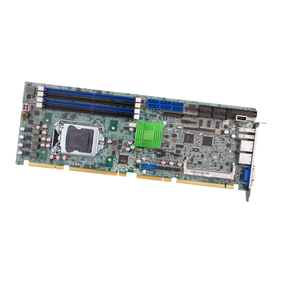
PCIE-Q170 Full-size PICMG 1.3 CPU Card 1.1 Introduction Figure 1-1: PCIE-Q170 The PCIE-Q170 is a full-size PICMG 1.3 CPU card. It accepts a Socket LGA1151 6th/7th generation Intel® Core™ i7/i5/i3, Pentium® or Celeron® processor and supports four 288-pin 2133 MHz dual-channel DDR4 DIMM modules up to 64 GB. The PCIE-Q170 provides two GbE interfaces through the Intel®... -
Page 19: Model Variations
PCIE-Q170 Full-size PICMG 1.3 CPU Card 1.2 Model Variations The model variations of the PCIE-Q170 series are listed below. Model No. Supported CPU iRIS-2400 Module Slot PCIE-Q170-R10 6th/7th generation LGA1151 Intel® Core™ i7/i5/i3, Pentium® or Celeron® PCIE-Q170-i2-R10 Table 1-1: PCIE-Q170 Model Variations 1.3 Features Some of the PCIE-Q170 motherboard features are listed below: Full-size PICMG 1.3 CPU card... -
Page 20: Connectors
PCIE-Q170 Full-size PICMG 1.3 CPU Card 1.4 Connectors The connectors on the PCIE-Q170 are shown in the figure below. Figure 1-2: Connectors Page 4... -
Page 21: Dimensions
PCIE-Q170 Full-size PICMG 1.3 CPU Card 1.5 Dimensions The main dimensions of the PCIE-Q170 are shown in the diagram below. Figure 1-3: PCIE-Q170 Dimensions (mm) Page 5... -
Page 22: Data Flow
PCIE-Q170 Full-size PICMG 1.3 CPU Card 1.6 Data Flow Figure 1-4 shows the data flow between the system chipset, the CPU and other components installed on the motherboard. Figure 1-4: Data Flow Diagram Page 6... -
Page 23: Technical Specifications
PCIE-Q170 Full-size PICMG 1.3 CPU Card 1.7 Technical Specifications The PCIE-Q170 technical specifications are listed below. Specification/Model PCIE-Q170 Form Factor Full-size PICMG 1.3 CPU card 6th/7th generation LGA1151 Intel® Core™ i7/i5/i3, Pentium® CPU Supported or Celeron® CPU Intel® Q170 Four 288-pin 2133/1867 MHz dual-channel unbuffered DDR4 Memory SDRAM DIMMs supported (system max. - Page 24 PCIE-Q170 Full-size PICMG 1.3 CPU Card Super I/O Controller Fintek F81866D-I Embedded Controller ITE IT8528E Watchdog Timer Software programmable supports 1~255 sec. system reset I/O Interface Connectors Audio Connector One audio connector (10-pin header) Chassis Intrusion One 2-pin header Digital I/O 8-bit digital I/O (10-pin header) Ethernet Two RJ-45 ports...
-
Page 25: Table 1-2: Pcie-Q170 Specifications
PCIE-Q170 Full-size PICMG 1.3 CPU Card Two USB 3.1 Gen 1 ports on rear panel Two USB 3.1 Gen 1 ports via internal box header * The Windows® 7 installation media does not include native driver support for USB 3.1 Gen 1. In order to use the USB USB 3.1 Gen 1 (5Gb/s) keyboard or mouse connected to a USB 3.1 Gen 1 port during OS installation, the user has to update the Windows®... -
Page 26: Packing List
PCIE-Q170 Full-size PICMG 1.3 CPU Card Chapter Packing List Page 10... -
Page 27: Anti-Static Precautions
PCIE-Q170 Full-size PICMG 1.3 CPU Card 2.1 Anti-static Precautions WARNING! Static electricity can destroy certain electronics. Make sure to follow the ESD precautions to prevent damage to the product, and injury to the user. Make sure to adhere to the following guidelines: Wear an anti-static wristband: Wearing an anti-static wristband can prevent ... -
Page 28: Packing List
PCIE-Q170 Full-size PICMG 1.3 CPU Card 2.3 Packing List NOTE: If any of the components listed in the checklist below are missing, do not proceed with the installation. Contact the IEI reseller or vendor the PCIE-Q170 was purchased from or contact an IEI sales representative directly by sending an email to sales@ieiworld.com. -
Page 29: Optional Items
PCIE-Q170 Full-size PICMG 1.3 CPU Card Quantity Item and Part Number Image Quick installation guide Table 2-1: Packing List 2.4 Optional Items The following are optional components which may be separately purchased: Item and Part Number Image RS-232/422/485 cable, 230 mm, P=2.54 (P/N: 32205-000702-100-RS) PS/2 KB/MS Y-cable with bracket (P/N: 19800-000075-RS) - Page 30 PCIE-Q170 Full-size PICMG 1.3 CPU Card Item and Part Number Image LGA1150 cooler kit (high-performance compatible, 65W) (P/N: CF-1150SB-R11) LGA1150 cooler kit (1U chassis compatible, 65W) (P/N: CF-1150SC-R20) LGA1150 cooler kit (high-performance compatible, 95W) (P/N: CF-1150SE-R11) LGA1150 cooler kit (1U chassis compatible, 54W) (P/N: CF-1150SF-R10) DisplayPort to HDMI converter board (for IEI iDP connector)
-
Page 31: Table 2-2: Optional Items
PCIE-Q170 Full-size PICMG 1.3 CPU Card Item and Part Number Image DisplayPort to DVI-D converter board (for IEI iDP connector) (P/N: DP-DVI-R10) DisplayPort to DisplayPort converter board (for IEI iDP connector) (P/N: DP-DP-R10) SATA to IDE/CompactFlash® converter board (P/N: SAIDE-KIT01-R10) Table 2-2: Optional Items Page 15... -
Page 32: Connectors
PCIE-Q170 Full-size PICMG 1.3 CPU Card Chapter Connectors Page 16... -
Page 33: Peripheral Interface Connectors
PCIE-Q170 Full-size PICMG 1.3 CPU Card 3.1 Peripheral Interface Connectors This chapter details all the peripheral interface connectors. 3.1.1 PCIE-Q170 Layout The figure below shows all the peripheral interface connectors. Figure 3-1: Peripheral Interface Connectors Page 17... -
Page 34: Peripheral Interface Connectors
PCIE-Q170 Full-size PICMG 1.3 CPU Card 3.1.2 Peripheral Interface Connectors The table below lists all the connectors on the board. Connector Type Label 4-pin Molex power +12V ATX power supply connector CPU12V1 connector Audio kit connector 10-pin header J_AUDIO1 Battery connector 2-pin wafer BAT1 Chassis intrusion connector... -
Page 35: External Interface Panel Connectors
PCIE-Q170 Full-size PICMG 1.3 CPU Card Connector Type Label RS-232/422/485 serial ports 10-pin box header COM3, COM4 S_ATA1, S_ATA2, SATA 6Gb/s drive connector 7-pin SATA connector S_ATA3, S_ATA4, S_ATA5, S_ATA6, SMBus connector 4-pin wafer SMB1 SPI flash connector 8-pin header JSPI1 SPI flash connector, EC 8-pin header... -
Page 36: Internal Peripheral Connectors
PCIE-Q170 Full-size PICMG 1.3 CPU Card 3.2 Internal Peripheral Connectors The section describes all of the connectors on the PCIE-Q170. 3.2.1 +12V ATX Power Connector CN Label: CPU12V1 CN Type: 4-pin Molex power connector, p=4.2 mm See Figure 3-2 CN Location: CN Pinouts: See Table 3-3 This connector provides power to the CPU. -
Page 37: Battery Connector
PCIE-Q170 Full-size PICMG 1.3 CPU Card Figure 3-3: Audio Connector Location Description Description HDA_SYNC HDA_BIT_CLK HDA_SDOUT HDA_SPKR HDA_SDIN HDA_RST# HDA_VCC HDA_GND HDA_+12V HDA_GND Table 3-4: Audio Connector Pinouts 3.2.3 Battery Connector CAUTION: Risk of explosion if battery is replaced by an incorrect type. Only certified engineers should replace the on-board battery. -
Page 38: Chassis Intrusion Connector
PCIE-Q170 Full-size PICMG 1.3 CPU Card Figure 3-4: Battery Connector Location Description VBATT Table 3-5: Battery Connector Pinouts 3.2.4 Chassis Intrusion Connector CN Label: CHASSIS1 CN Type: 2-pin header, p=2.54 mm CN Location: See Figure 3-5 See Table 3-6 CN Pinouts: The chassis intrusion connector is for a chassis intrusion detection sensor or switch that detects if a chassis component is removed or replaced. -
Page 39: Crt Fw Update Connector
PCIE-Q170 Full-size PICMG 1.3 CPU Card 3.2.5 CRT FW Update Connector CN Label: J_CRTFW1 CN Type: 3-pin header, p=2.00 mm CN Location: See Figure 3-6 CN Pinouts: See Table 3-7 The CRT FW update connector is used to update the CRT firmware. Figure 3-6: CRT FW Update Connector Location Description Table 3-7: CRT FW Update Connector Pinouts... -
Page 40: Digital I/O Connector
PCIE-Q170 Full-size PICMG 1.3 CPU Card Figure 3-7: DDR4 DIMM Socket Locations 3.2.7 Digital I/O Connector CN Label: DIO1 CN Type: 10-pin header, p=2.00 mm CN Location: See Figure 3-8 CN Pinouts: See Table 3-8 The digital I/O connector provides programmable input and output for external devices. Figure 3-8: Digital I/O Connector Location Description Description... -
Page 41: Ec Debug Connector
PCIE-Q170 Full-size PICMG 1.3 CPU Card 3.2.8 EC Debug Connector CN Label: CN Type: 18-pin header, p=2.00 mm CN Location: See Figure 3-9 CN Pinouts: See Table 3-9 The EC debug connector is used for EC debug. Figure 3-9: EC Debug Connector Location Description Description EC_EPP_STB#... -
Page 42: Fan Connector (Cpu)
PCIE-Q170 Full-size PICMG 1.3 CPU Card 3.2.9 Fan Connector (CPU) CN Label: CPU_FAN1 CN Type: 4-pin wafer, p=2.54 mm CN Location: See Figure 3-10 CN Pinouts: See Table 3-10 The fan connector attaches to a CPU cooling fan. Figure 3-10: CPU Fan Connector Location Description +12V FANIO... -
Page 43: Front Panel Connector
PCIE-Q170 Full-size PICMG 1.3 CPU Card The fan connector attaches to a system cooling fan. Figure 3-11: System Fan Connector Location Description FANIO +12V (PWM) Table 3-11: System Fan (SYS_FAN1) Connector Pinouts 3.2.11 Front Panel Connector CN Label: F_PANEL1 CN Type: 14-pin header, p=2.54 mm See Figure 3-12 CN Location:... -
Page 44: I 2 C Connector
PCIE-Q170 Full-size PICMG 1.3 CPU Card Function Description Function Description Speaker BEEP_PWR Power LED IPMI ID_LED+ IPMI LED IPMI ID_LED- PWRBTN_SW# Speaker PC_BEEP Power Button EXTRST- HDD LED Reset SATA_LED# Table 3-12: Front Panel Connector Pinouts 3.2.12 I C Connector CN Label: I2C1 CN Type:... -
Page 45: Internal Displayport Connector
PCIE-Q170 Full-size PICMG 1.3 CPU Card 3.2.13 Internal DisplayPort Connector CN Label: CN Type: 20-pin box header, p=2.00 mm CN Location: See Figure 3-14 CN Pinouts: See Table 3-14 The DisplayPort connector supports HDMI, LVDS, VGA, DVI and DisplayPort graphics interfaces with up to 3840x2160 resolutions. -
Page 46: Iris-2400 Module Slot (Pcie-Q170-I2-R10 Only)
PCIE-Q170 Full-size PICMG 1.3 CPU Card 3.2.14 iRIS-2400 Module Slot (PCIE-Q170-i2-R10 Only) CN Label: IPMI1 CN Type: iRIS-2400 module slot CN Location: See Figure 3-15 The iRIS-2400 module slot allows installation of the iRIS-2400 module. Figure 3-15: iRIS-2400 Module Slot Location WARNING: The iRIS-2400 module slot is designed to install the iRIS-2400 module only. -
Page 47: Lan Led Connectors
PCIE-Q170 Full-size PICMG 1.3 CPU Card Figure 3-16: Keyboard and Mouse Connector Location Description Mouse Data Mouse Clock Keyboard Data Keyboard Clock Table 3-15: Keyboard and Mouse Connector Pinouts 3.2.16 LAN LED Connectors CN Label: LED_LAN1, LED_LAN2 CN Type: 2-pin header, p=2.54 mm CN Location: See Figure 3-17 See Table 3-16 and Table 3-17... -
Page 48: Parallel Port Connector
PCIE-Q170 Full-size PICMG 1.3 CPU Card Description +3.3V LAN1_LED_LINK#_ACT Table 3-16: LAN1 LED Connector (LED_LAN1) Pinouts Description +3.3V LAN2_LED_LINK#_ACT Table 3-17: LAN2 LED Connector (LED_LAN2) Pinouts 3.2.17 Parallel Port Connector CN Label: LPT1 CN Type: 26-pin box header, p=2.54 mm CN Location: See Figure 3-18 CN Pinouts:... -
Page 49: Pcie Mini Slot
PCIE-Q170 Full-size PICMG 1.3 CPU Card RPD4 RPD5 RPD6 RPD7 SIO_ACK# SIO_BUSY SIO_PE SIO_SLCT Table 3-18: Parallel Port Connector Pinouts 3.2.18 PCIe Mini Slot CN Label: MPCIE1 CN Type: PCIe Mini slot CN Location: See Figure 3-19 CN Pinouts: See Table 3-19 The PCIe Mini slot is for installing a full-size/half-size PCIe Mini expansion card, such as an mSATA SSD or wireless LAN card. -
Page 50: Table 3-19: Pcie Mini Slot Pinouts
PCIE-Q170 Full-size PICMG 1.3 CPU Card Description Description PCIE_WAKE# +3.3V 1.5V MSATA_CLK# MSATA _CLK PLTRST_N +3.3V PLTRST_N SATA_RX-/PCIE_RX- +3.3V SATA_RX+/PCIE_RX+ 1.5V SMB_CLK SATA_TX-/PCIE_TX- SMB_DATA SATA_TX+/PCIE_TX+ USB_DATA- USB_DATA+ +3.3V +3.3V +3.3V CLINK_CLK CLINK_DATA 1.5V CLINK_RST# MSATA_DET +3.3V Table 3-19: PCIe Mini Slot Pinouts Page 34... -
Page 51: Power Button
PCIE-Q170 Full-size PICMG 1.3 CPU Card 3.2.19 Power Button CN Label: PWR_SW1 CN Type: Push button CN Location: See Figure 3-20 The on-board power button controls system power. Figure 3-20: Power Button Location 3.2.20 RS-232 Serial Port Connectors CN Label: COM1, COM2 CN Type: 10-pin box header, p=2.54 mm... -
Page 52: Rs-232/422/485 Serial Port Connectors
PCIE-Q170 Full-size PICMG 1.3 CPU Card Description Description SOUT Table 3-20: RS-232 Serial Port Connector Pinouts 3.2.21 RS-232/422/485 Serial Port Connectors CN Label: COM3, COM4 CN Type: 10-pin box header, p=2.54 mm See Figure 3-22 CN Location: CN Pinouts: See Table 3-21 Each of these connectors provides RS-232/422/485 connections. -
Page 53: Sata 6Gb/S Drive Connector
PCIE-Q170 Full-size PICMG 1.3 CPU Card Description Description SOUT Table 3-21: RS-232/422/485 Serial Port Connector Pinouts The user may use the RS-232/422/485 cable to connect to a serial device. The pinouts of the DB-9 connector are listed below. RS-232 Pinouts RS-422 Pinouts RS-485 Pinouts Table 3-22: DB-9 RS-232/422/485 Pinouts... -
Page 54: Smbus Connector
PCIE-Q170 Full-size PICMG 1.3 CPU Card Figure 3-23: SATA 6Gb/s Drive Connector Locations Description Description Table 3-23: SATA 6Gb/s Drive Connector Pinouts NOTE: If the user shorts the mSATA setup jumper (MSATA_SW1) to force the system to enable mSATA device or an mSATA device is detected, the S_ATA6 connector will be disabled. -
Page 55: Spi Flash Connector
PCIE-Q170 Full-size PICMG 1.3 CPU Card The SMBus (System Management Bus) connector provides low-speed system management communications. Figure 3-24: SMBus Connector Location Description SMB_DATA SMB_CLK Table 3-24: SMBus Connector Pinouts 3.2.24 SPI Flash Connector CN Label: JSPI1 CN Type: 8-pin header, p=2.54 mm CN Location: See Figure 3-25 CN Pinouts:... -
Page 56: Spi Flash Connector, Ec
PCIE-Q170 Full-size PICMG 1.3 CPU Card Description Description +3.3V SPI_CS SPI_CLK_SW SPI_SO_SW SPI_SI_SW Table 3-25: SPI Flash Connector Pinouts 3.2.25 SPI Flash Connector, EC CN Label: JSPI2 CN Type: 8-pin header, p=2.54 mm See Figure 3-26 CN Location: CN Pinouts: See Table 3-26 The SPI flash connector is used to flash the EC ROM. -
Page 57: Tpm Connector
PCIE-Q170 Full-size PICMG 1.3 CPU Card 3.2.26 TPM Connector CN Label: TPM1 CN Type: 20-pin header, p=2.54 mm CN Location: See Figure 3-27 CN Pinouts: See Table 3-27 The TPM connector connects to a TPM module. Figure 3-27: TPM Connector Location Description Description LCLK... -
Page 58: Usb 2.0 Connectors
PCIE-Q170 Full-size PICMG 1.3 CPU Card 3.2.27 USB 2.0 Connectors CN Label: USB1, USB2, USB3 CN Type: 8-pin header, p=2.54 mm CN Location: See Figure 3-28 CN Pinouts: See Table 3-28 The USB 2.0 connectors connect to USB 2.0 devices. Each pin header provides two USB 2.0 ports. -
Page 59: Usb 2.0 Connector (Type A)
PCIE-Q170 Full-size PICMG 1.3 CPU Card 3.2.28 USB 2.0 Connector (Type A) CN Label: USB4 CN Type: USB Type A CN Location: See Figure 3-29 CN Pinouts: See Table 3-29 The USB Type A connector connects to a USB 2.0/1.1 device. Figure 3-29: USB 2.0 Connector (Type A) Pinout Location Description DATA-... -
Page 60: Usb 3.1 Gen 1 Connector
PCIE-Q170 Full-size PICMG 1.3 CPU Card 3.2.29 USB 3.1 Gen 1 Connector CN Label: USB3_34 CN Type: 19-pin box header, p=2 mm CN Location: See Figure 3-30 CN Pinouts: See Table 3-30 The USB 3.1 Gen 1 connector connects to USB 3.1 Gen 1 devices. This connector provides two USB 3.1 Gen 1 ports. -
Page 61: External Peripheral Interface Connector
PCIE-Q170 Full-size PICMG 1.3 CPU Card 3.3 External Peripheral Interface Connector Panel The figure below shows the external peripheral interface connector (EPIC) panel. The EPIC panel consists of the following: Figure 3-31: External Peripheral Interface Connector 3.3.1 Ethernet Connectors CN Label: LAN1, LAN2 CN Type: RJ-45... -
Page 62: Usb 3.1 Gen 1 Connectors
PCIE-Q170 Full-size PICMG 1.3 CPU Card 3.3.2 USB 3.1 Gen 1 Connectors CN Label: USB3_1, USB3_2 CN Type: USB 3.1 Gen 1 Type A CN Location: See Figure 3-31 CN Pinouts: See Table 3-32 There are two external USB 3.1 Gen 1 connectors on the PCIE-Q170. Description Description VBUS... -
Page 63: Figure 3-33: Vga Connector
PCIE-Q170 Full-size PICMG 1.3 CPU Card Description Description GREEN BLUE HOT PLUG DETECT DDCDA HSYNC VSYNC DDCCLK Table 3-33: VGA Connector Pinouts Figure 3-33: VGA Connector Page 47... -
Page 64: Installation
PCIE-Q170 Full-size PICMG 1.3 CPU Card Chapter Installation Page 48... -
Page 65: Anti-Static Precautions
PCIE-Q170 Full-size PICMG 1.3 CPU Card 4.1 Anti-static Precautions WARNING: Failure to take ESD precautions during the installation of the PCIE-Q170 may result in permanent damage to the PCIE-Q170 and severe injury to the user. Electrostatic discharge (ESD) can cause serious damage to electronic components, including the PCIE-Q170. - Page 66 PCIE-Q170 Full-size PICMG 1.3 CPU Card WARNING: The installation instructions described in this manual should be carefully followed in order to prevent damage to the components and injury to the user. Before and during the installation please DO the following: Read the user manual: ...
-
Page 67: Socket Lga1151 Cpu Installation
PCIE-Q170 Full-size PICMG 1.3 CPU Card 4.3 Socket LGA1151 CPU Installation WARNING: CPUs are expensive and sensitive components. When installing the CPU please be careful not to damage it in anyway. Make sure the CPU is installed properly and ensure the correct cooling kit is properly installed. -
Page 68: Figure 4-2: Remove Protective Cover
PCIE-Q170 Full-size PICMG 1.3 CPU Card Figure 4-2: Remove Protective Cover Step 3: Inspect the CPU socket. Make sure there are no bent pins and make sure the socket contacts are free of foreign material. If any debris is found, remove it with compressed air. -
Page 69: Figure 4-3: Insert The Socket Lga1151 Cpu
PCIE-Q170 Full-size PICMG 1.3 CPU Card Step 7: Insert the CPU. Gently insert the CPU into the socket. If the CPU pins are properly aligned, the CPU should slide into the CPU socket smoothly. See Figure 4-3. Figure 4-3: Insert the Socket LGA1151 CPU Step 8: Close the CPU socket. -
Page 70: Socket Lga1151 Cooling Kit Installation
PCIE-Q170 Full-size PICMG 1.3 CPU Card Step 9: Connect the 12 V power to the board. Connect the 12 V power from the power supply to the board. Step 0: 4.4 Socket LGA1151 Cooling Kit Installation WARNING: DO NOT attempt to install a push-pin cooling fan. The pre-installed support bracket prevents the board from bending and is ONLY compatible with captive screw type cooling fans. -
Page 71: Figure 4-5: Cooling Kit Support Bracket
PCIE-Q170 Full-size PICMG 1.3 CPU Card Figure 4-5: Cooling Kit Support Bracket Step 2: Place the cooling kit onto the socket LGA1151 CPU. Make sure the CPU cable can be properly routed when the cooling kit is installed. Step 3: Mount the cooling kit. -
Page 72: Dimm Installation
PCIE-Q170 Full-size PICMG 1.3 CPU Card 4.5 DIMM Installation To install a DIMM, please follow the steps below and refer to Figure 4-6. Figure 4-6: DIMM Installation Step 1: Open the DIMM socket handles. Open the two handles outwards as far as they can. -
Page 73: Iris-2400 Module Installation (Optional)
PCIE-Q170 Full-size PICMG 1.3 CPU Card 4.6 iRIS-2400 Module Installation (Optional) WARNING: The iRIS-2400 module slot is designed to install the IEI iRIS-2400 IPMI 2.0 module only. DO NOT install other modules into the iRIS module slot. Doing so may cause damage to the PCIE-Q170. To install the iRIS-2400 module, please follow the steps below and refer to Figure 4-7. -
Page 74: Full-Size Pcie Mini Card Installation
PCIE-Q170 Full-size PICMG 1.3 CPU Card 4.7 Full-size PCIe Mini Card Installation The PCIe Mini card slot allows installation of either a full-size or half-size PCIe Mini card. To install a full-size PCIe Mini card, please follow the steps below. Step 1: Locate the PCIe Mini card slot. -
Page 75: Half-Size Pcie Mini Card Installation
PCIE-Q170 Full-size PICMG 1.3 CPU Card Step 4: Secure the full-size PCIe Mini card. Secure the full-size PCIe Mini card with the retention screw previously removed (Figure 4-10). Step 0: Figure 4-10: Securing the Full-size PCIe Mini Card 4.8 Half-size PCIe Mini Card Installation The PCIe Mini card slot allows installation of either a full-size or half-size PCIe Mini card. -
Page 76: Figure 4-11: Installing The Standoff
PCIE-Q170 Full-size PICMG 1.3 CPU Card Figure 4-11: Installing the Standoff Step 3: Insert into the socket at an angle. Line up the notch on the card with the notch on the slot. Slide the PCIe Mini card into the slot at an angle of about 20º (Figure 4-12). Figure 4-12: Inserting the Half-size PCIe Mini Card into the Slot at an Angle Step 4: Secure the half-size PCIe Mini card. -
Page 77: System Configuration
PCIE-Q170 Full-size PICMG 1.3 CPU Card Figure 4-13: Securing the Half-size PCIe Mini Card 4.9 System Configuration The system configuration should be performed before installation. 4.9.1 AT/ATX Power Mode Setting The AT and ATX power mode selection is made through the AT/ATX power mode switch which is shown in Figure 4-14. -
Page 78: Clear Cmos Button
PCIE-Q170 Full-size PICMG 1.3 CPU Card 4.9.2 Clear CMOS Button To reset the BIOS, remove the on-board battery and press the clear CMOS button for three seconds or more. The clear CMOS button location is shown in Figure 4-15. Figure 4-15: Clear CMOS Button Location 4.9.3 PCIe x4 Channel Mode Setup The user can select to use either one PCIe x4 slot or four PCIe x1 slots on the backplane via the BIOS switch. -
Page 79: Pcie X16 Channel Mode Setup
PCIE-Q170 Full-size PICMG 1.3 CPU Card To switch BIOS1 to BIOS2 or BIOS2 to BIOS1 successfully, please follow the steps below. Step 1: Unplug the system power cord. Step 2: Switch BIOS1 to BIOS2 or BIOS2 to BIOS1 by moving the BIOS switch to BIOS1 or BIOS2 position as shown in Figure 4-16. -
Page 80: Flash Descriptor Security Override Jumper
PCIE-Q170 Full-size PICMG 1.3 CPU Card 4.9.5 Flash Descriptor Security Override Jumper The flash descriptor security override jumper (J_FLASH2) allows to enable or disable the ME firmware update. Refer to Table 4-4 and Figure 4-17 for the jumper location and settings. -
Page 81: Usb Power Selection
PCIE-Q170 Full-size PICMG 1.3 CPU Card 4.9.6 USB Power Selection The USB power selection is made through the BIOS menu in “Chipset PCH-IO Configuration”. Use the USB Power SW1 and the USB Power SW2 BIOS options to configure the correspondent USB ports (see Table 4-5) and refer to Table 4-6 to select the USB power source. -
Page 82: Msata Setup
PCIE-Q170 Full-size PICMG 1.3 CPU Card 4.9.7 mSATA Setup The mSATA setup jumper specifies whether to automatically detect the mSATA device installed in the PCIe Mini slot (MPCIE1). If the user shorts the mSATA setup jumper to force the system to enable mSATA device, the S_ATA6 connector will be disabled. Setting Description Open... -
Page 83: Figure 4-19: Sata Drive Cable Connection
PCIE-Q170 Full-size PICMG 1.3 CPU Card Figure 4-19: SATA Drive Cable Connection Step 3: Connect the cable to the SATA disk. Connect the connector on the other end of the cable to the connector at the back of the SATA drive. See Figure 4-20. Step 4: Connect the SATA power cable. -
Page 84: Adding Usb 3.1 Gen 1 Drivers To A Windows 7 Installation Image
PCIE-Q170 Full-size PICMG 1.3 CPU Card Figure 4-20: SATA Power Drive Connection The SATA power cable can be bought from IEI. See Optional Items in Section 2.4. 4.11 Adding USB 3.1 Gen 1 Drivers to a Windows 7 Installation Image The Windows 7 installation media does not include native driver support for USB 3.1 Gen 1. -
Page 85: Figure 4-21: Windows 7 Usb 3.0 Creator Utility
PCIE-Q170 Full-size PICMG 1.3 CPU Card Step 3: Extract the downloaded file to a temporary folder on a computer where the user has logged in as the administrator. NOTE: The OS version of the computer can be Windows 7, Windows 8.1 or Windows 10. -
Page 86: Intel ® Amt Setup Procedure
PCIE-Q170 Full-size PICMG 1.3 CPU Card Step 8: Wait for the process to finish. It may take up to 15 minutes. Figure 4-22: Update Process is Complete Step 9: Now the user can proceed with the Windows 7 installation using the updated installer. -
Page 87: Ipmi Setup Procedure (Pcie-Q170-I2-R10 Only)
PCIE-Q170 Full-size PICMG 1.3 CPU Card NOTE: To change the password, enter a new password following the strong password rule (containing at least one upper case letter, one lower case letter, one digit and one special character, and be at least eight characters). -
Page 88: Figure 4-23: Iei Iman Web Address
PCIE-Q170 Full-size PICMG 1.3 CPU Card a. Copy the Ipmitool.exe file to a bootable USB flash drive. b. Insert the USB flash drive to the PCIE-Q170-i2 c. The PCIE-Q170-i2 boots from the USB flash drive d. Enter the following command: ipmitool 20 30 02 01 03 00 00 (there is a space between each two-digit number) e. -
Page 89: Figure 4-24: Iei Iman Web Gui
PCIE-Q170 Full-size PICMG 1.3 CPU Card Figure 4-24: IEI iMAN Web GUI NOTE: To understand how to use the IEI iMAN Web GUI, please refer to the iRIS-2400 Web GUI user manual in the utility CD came with the PCIE-Q170. The user manual describes each function in detail. Page 73... -
Page 90: Bios
PCIE-Q170 Full-size PICMG 1.3 CPU Card Chapter BIOS Page 74... -
Page 91: Introduction
PCIE-Q170 Full-size PICMG 1.3 CPU Card 5.1 Introduction The BIOS is programmed onto the BIOS chip. The BIOS setup program allows changes to certain system settings. This chapter outlines the options that can be changed. NOTE: Some of the BIOS options may vary throughout the life cycle of the product and are subject to change without prior notice. -
Page 92: Getting Help
PCIE-Q170 Full-size PICMG 1.3 CPU Card Function Main Menu – Quit and not save changes into CMOS Status Page Setup Menu and Option Page Setup Menu -- Exit current page and return to Main Menu General help, only for Status Page Setup Menu and Option Page Setup Menu Load previous values Load optimized defaults... - Page 93 PCIE-Q170 Full-size PICMG 1.3 CPU Card Aptio Setup Utility – Copyright (C) 2016 American Megatrends, Inc. Main Advanced Chipset Security Boot Save & Exit Server Mgmt BIOS Information Set the Date. Use Tab to BIOS Vendor American Megatrends switch between Date Core Version 5.11 elements.
-
Page 94: Advanced
PCIE-Q170 Full-size PICMG 1.3 CPU Card The Main menu has two user configurable fields: System Date [xx/xx/xx] Use the System Date option to set the system date. Manually enter the day, month and year. System Time [xx:xx:xx] Use the System Time option to set the system time. Manually enter the hours, minutes and seconds. -
Page 95: Trusted Computing
PCIE-Q170 Full-size PICMG 1.3 CPU Card 5.3.1 Trusted Computing Use the Trusted Computing menu (BIOS Menu 3) to configure settings related to the Trusted Computing Group (TCG) Trusted Platform Module (TPM). Aptio Setup Utility – Copyright (C) 2016 American Megatrends, Inc. Advanced Configuration Enables or Disables BIOS... -
Page 96: Acpi Settings
PCIE-Q170 Full-size PICMG 1.3 CPU Card 5.3.2 ACPI Settings The ACPI Settings menu (BIOS Menu 4) configures the Advanced Configuration and Power Interface (ACPI) options. Aptio Setup Utility – Copyright (C) 2016 American Megatrends, Inc. Advanced ACPI Settings Select the highest ACPI sleep state the system ACPI Sleep State [S3 (Suspend to RAM)]... -
Page 97: Amt Configuration
PCIE-Q170 Full-size PICMG 1.3 CPU Card 5.3.3 AMT Configuration The AMT Configuration menu (BIOS Menu 5) allows the Intel® AMT options to be configured. Aptio Setup Utility – Copyright (C) 2016 American Megatrends, Inc. Advanced Intel AMT [Enabled] Enable/Disable Intel (R) Un-Configure ME [Disabled] Active Management... -
Page 98: Super Io Configuration
PCIE-Q170 Full-size PICMG 1.3 CPU Card 5.3.4 Super IO Configuration Use the Super IO Configuration menu (BIOS Menu 6) to set or change the configurations for the serial ports and parallel port. Aptio Setup Utility – Copyright (C) 2016 American Megatrends, Inc. Advanced Super IO Configuration Set Parameters of Serial... -
Page 99: Serial Port N Configuration
PCIE-Q170 Full-size PICMG 1.3 CPU Card 5.3.4.1 Serial Port n Configuration Use the Serial Port n Configuration menu (BIOS Menu 7) to configure the serial port n. Aptio Setup Utility – Copyright (C) 2016 American Megatrends, Inc. Advanced Serial Port n Configuration Enable or Disable Serial Port (COM) Serial Port... - Page 100 PCIE-Q170 Full-size PICMG 1.3 CPU Card IO=3F8h; Serial Port I/O port address is 3F8h and the interrupt IRQ=3, 4, 11 address is IRQ3, 4, 11 IO=2F8h; Serial Port I/O port address is 2F8h and the interrupt IRQ=3, 4, 11 address is IRQ3, 4, 11 ...
- Page 101 PCIE-Q170 Full-size PICMG 1.3 CPU Card IO=2F8h; Serial Port I/O port address is 2F8h and the interrupt IRQ=3, 4, 11 address is IRQ3, 4, 11 IO=3E8h; Serial Port I/O port address is 3E8h and the interrupt IRQ=3, 4, 11 address is IRQ3, 4, 11 ...
- Page 102 PCIE-Q170 Full-size PICMG 1.3 CPU Card IO=3E8h; Serial Port I/O port address is 3E8h and the interrupt IRQ=3, 4, 11 address is IRQ3, 4, 11 IO=2E8h; Serial Port I/O port address is 2E8h and the interrupt IRQ=3, 4, 11 address is IRQ3, 4, 11 ...
-
Page 103: Parallel Port Configuration
PCIE-Q170 Full-size PICMG 1.3 CPU Card IO=2F8h; Serial Port I/O port address is 2F8h and the interrupt IRQ=3, 4, 11 address is IRQ3, 4, 11 IO=3E8h; Serial Port I/O port address is 3E8h and the interrupt IRQ=3, 4, 11 address is IRQ3, 4, 11 ... -
Page 104: Iwdd H/W Monitor
PCIE-Q170 Full-size PICMG 1.3 CPU Card Parallel Port [Enabled] Use the Parallel Port option to enable or disable the parallel port. Disabled Disable the parallel port Enabled Enable the parallel port EFAULT Device Mode [STD Printer Mode] ... - Page 105 PCIE-Q170 Full-size PICMG 1.3 CPU Card Aptio Setup Utility – Copyright (C) 2016 American Megatrends, Inc. Advanced PC Health Status Smart Fan Mode Select CPU temperature : +40ºC SYS temperature : +36ºC --------------------- CPU_FAN1 Speed : 1416 RPM : Select Screen SYS_FAN1 Speed : N/A ↑...
-
Page 106: Smart Fan Mode Configuration
PCIE-Q170 Full-size PICMG 1.3 CPU Card 5.3.5.1 Smart Fan Mode Configuration Use the Smart Fan Mode Configuration submenu (BIOS Menu 10) to configure fan speed settings. Aptio Setup Utility – Copyright (C) 2016 American Megatrends, Inc. Advanced Smart Fan Mode Configuration Smart Fan Mode Select CPU_FAN1 Smart Fan Control [Auto Mode]... -
Page 107: Rtc Wake Settings
PCIE-Q170 Full-size PICMG 1.3 CPU Card Auto mode fan slope PWM Use the + or – key to change the Auto mode fan slope PWM value. Enter a decimal number between 1 and 8. 5.3.6 RTC Wake Settings The RTC Wake Settings menu (BIOS Menu 11) enables the system to wake at the specified time. -
Page 108: Serial Port Console Redirection
PCIE-Q170 Full-size PICMG 1.3 CPU Card selected: Wake up date Wake up hour Wake up minute Wake up second After setting the alarm, the computer turns itself on from a suspend state when the alarm goes off. 5.3.7 Serial Port Console Redirection The Serial Port Console Redirection menu (BIOS Menu 12) allows the console redirection options to be configured. - Page 109 PCIE-Q170 Full-size PICMG 1.3 CPU Card Console Redirection [Disabled] Use Console Redirection option to enable or disable the console redirection function. Disabled Disabled the console redirection function EFAULT Enabled Enabled the console redirection function The following options are available in the Console Redirection Settings submenu when the Console Redirection option is enabled.
- Page 110 PCIE-Q170 Full-size PICMG 1.3 CPU Card Parity [None] Use the Parity option to specify the parity bit that can be sent with the data bits for detecting the transmission errors. None No parity bit is sent with the data bits. EFAULT ...
-
Page 111: Legacy Console Redirection Settings
PCIE-Q170 Full-size PICMG 1.3 CPU Card 5.3.7.1 Legacy Console Redirection Settings Aptio Setup Utility – Copyright (C) 2016 American Megatrends, Inc. Advanced Legacy Serial Redirection Port [COM1] Select a COM port to display redirection of Legacy OS and Legacy OPROM Messages. --------------------- : Select Screen ↑... -
Page 112: Cpu Configuration
PCIE-Q170 Full-size PICMG 1.3 CPU Card 5.3.8 CPU Configuration Use the CPU Configuration menu (BIOS Menu 14) to view detailed CPU specifications or enable the Intel Virtualization Technology. Aptio Setup Utility – Copyright (C) 2016 American Megatrends, Inc. Advanced CPU Configuration Enable for Windows XP and Linux (OS optimized for Intel(R) Core(TM) i3-6100TE CPU @ 2.70GHz... - Page 113 PCIE-Q170 Full-size PICMG 1.3 CPU Card Active Processor Cores [All] Use the Active Processor Cores BIOS option to enable numbers of cores in the processor package. Enable all cores in the processor package. EFAULT Enable one core in the processor package. Intel Virtualization Technology [Disabled] ...
-
Page 114: Sata Configuration
PCIE-Q170 Full-size PICMG 1.3 CPU Card Intel TXT(LT) Support [Disabled] Use the Intel TXT(LT) Support option to enable or disable the Intel(R) TXT(LT) support. Disabled Disables Intel® TXT(LT) support EFAULT Enabled Enables Intel® TXT(LT) support 5.3.9 SATA Configuration Use the SATA Configuration menu (BIOS Menu 15) to change and/or set the configuration of the SATA devices installed in the system. -
Page 115: Nvme Configuration
PCIE-Q170 Full-size PICMG 1.3 CPU Card Hot Plug [Disabled] Use the Hot Plug option to designate the correspondent SATA port as hot-pluggable. Disabled Disables the hot-pluggable function of the SATA port. EFAULT Enabled Designates the SATA port as hot-pluggable. 5.3.10 NVMe Configuration Use the NVMe Configuration (BIOS Menu 16) menu to display the NVMe controller and device information. -
Page 116: Usb Configuration
PCIE-Q170 Full-size PICMG 1.3 CPU Card 5.3.11 USB Configuration Use the USB Configuration menu (BIOS Menu 17) to read USB configuration information and configure the USB settings. Aptio Setup Utility – Copyright (C) 2016 American Megatrends, Inc. Advanced USB Configuration Enables Legacy USB support. -
Page 117: Iei Feature
PCIE-Q170 Full-size PICMG 1.3 CPU Card 5.3.12 iEi Feature Use the iEi Feature menu (BIOS Menu 18) to configure One Key Recovery function. Aptio Setup Utility – Copyright (C) 2016 American Megatrends, Inc. Advanced iEi Feature Auto Recovery Function Reboot and recover Auto Recovery Function [Disabled] system automatically... -
Page 118: Chipset
PCIE-Q170 Full-size PICMG 1.3 CPU Card 5.4 Chipset Use the Chipset menu (BIOS Menu 19) to access the PCH IO and System Agent (SA) configuration menus. WARNING! Setting the wrong values for the Chipset BIOS selections in the Chipset BIOS menu may cause the system to malfunction. Aptio Setup Utility –... -
Page 119: System Agent (Sa) Configuration
PCIE-Q170 Full-size PICMG 1.3 CPU Card 5.4.1 System Agent (SA) Configuration Use the System Agent (SA) Configuration menu (BIOS Menu 20) to configure the System Agent (SA) parameters. Aptio Setup Utility – Copyright (C) 2016 American Megatrends, Inc. Chipset VT-d Supported VT-d capability VT-d... -
Page 120: Graphics Configuration
PCIE-Q170 Full-size PICMG 1.3 CPU Card 5.4.1.1 Graphics Configuration Use the Graphics Configuration (BIOS Menu 21) menu to configure the video device connected to the system. Aptio Setup Utility – Copyright (C) 2016 American Megatrends, Inc. Chipset Graphics Configuration Select which of IGFX/PEG/PCI Graphics Primary Display [Auto]... - Page 121 PCIE-Q170 Full-size PICMG 1.3 CPU Card DVMT Pre-Allocated [32M] Use the DVMT Pre-Allocated option to set the amount of system memory allocated to the integrated graphics processor when the system boots. The system memory allocated can then only be used as graphics memory, and is no longer available to applications or the operating system.
-
Page 122: Peg Port Configuration
PCIE-Q170 Full-size PICMG 1.3 CPU Card 5.4.1.2 PEG Port Configuration Aptio Setup Utility – Copyright (C) 2016 American Megatrends, Inc. Chipset PEG Port Configuration Select PEG Port Link Width as x16 or 2x8 PEG Link Width Configuration [1x16] configuration. PEG 0:1:0 Not Present ---------------------- Enable Root Port... -
Page 123: Memory Configuration
PCIE-Q170 Full-size PICMG 1.3 CPU Card Max Link Speed [Auto] Use the Max Link Speed option to select the maximum link speed of the PCI Express slot. The following options are available: Default Auto Gen1 Gen2 Gen3 ... -
Page 124: Pch-Io Configuration
PCIE-Q170 Full-size PICMG 1.3 CPU Card 5.4.2 PCH-IO Configuration Use the PCH-IO Configuration menu (BIOS Menu 24) to configure the PCH parameters. Aptio Setup Utility – Copyright (C) 2016 American Megatrends, Inc. Chipset Auto Power Button Status [Disable (ATX)] Select AC power state Restore AC Power Loss [Last State] when power is re-applied... -
Page 125: Table 5-2: Bios Options And Configured Usb Ports
PCIE-Q170 Full-size PICMG 1.3 CPU Card USB Power SW1 [+5V DUAL] Use the USB Power SW1 BIOS option to configure the USB power source for the corresponding USB connectors (Table 5-2). Sets the USB power source to +5V ... -
Page 126: Pci Express Configuration
PCIE-Q170 Full-size PICMG 1.3 CPU Card 5.4.2.1 PCI Express Configuration The PCI Express port number in the PCI Express Configuration menu varies by BIOS (BIOS1 or BIOS2). For detailed information, please refer to Section 4.9.3. For BIOS1: Aptio Setup Utility – Copyright (C) 2016 American Megatrends, Inc. Chipset PCI Express Configuration PCIEX1 Slot Settings. - Page 127 PCIE-Q170 Full-size PICMG 1.3 CPU Card 5.4.2.1.1 PCIEX1 Slot/PCIEX4 Slot/MPCIE Slot Aptio Setup Utility – Copyright (C) 2016 American Megatrends, Inc. Advanced PCIe Speed [Auto] Select PCI Express port Detect Non-Compliance Device [Disabled] speed. --------------------- : Select Screen ↑ ↓: Select Item Enter: Select +/-: Change Opt.
-
Page 128: Hd Audio Configuration
PCIE-Q170 Full-size PICMG 1.3 CPU Card 5.4.2.2 HD Audio Configuration Use the HD Audio Configuration menu (BIOS Menu 28) to configure the PCH Azalia settings. Aptio Setup Utility – Copyright (C) 2016 American Megatrends, Inc. Chipset HD Audio Configuration Control Detection of the HD-Audio device. -
Page 129: Security
PCIE-Q170 Full-size PICMG 1.3 CPU Card 5.5 Security Use the Security menu (BIOS Menu 29) to set system and user passwords. Aptio Setup Utility – Copyright (C) 2016 American Megatrends, Inc. Main Advanced Chipset Security Boot Save & Exit Server Mgmt Password Description Set Administrator Password... -
Page 130: Boot
PCIE-Q170 Full-size PICMG 1.3 CPU Card 5.6 Boot Use the Boot menu (BIOS Menu 30) to configure system boot options. Aptio Setup Utility – Copyright (C) 2016 American Megatrends, Inc. Main Advanced Chipset Security Boot Save & Exit Server Mgmt Boot Configuration Select the keyboard Bootup NumLock State... - Page 131 PCIE-Q170 Full-size PICMG 1.3 CPU Card Quiet Boot [Enabled] Use the Quiet Boot BIOS option to select the screen display when the system boots. Disabled Normal POST messages displayed Enabled OEM Logo displayed instead of POST messages EFAULT Launch PXE OpROM [Disabled] ...
-
Page 132: Save & Exit
PCIE-Q170 Full-size PICMG 1.3 CPU Card 5.7 Save & Exit Use the Safe & Exit menu (BIOS Menu 31) to load default BIOS values, optimal failsafe values and to save configuration changes. Aptio Setup Utility – Copyright (C) 2016 American Megatrends, Inc. Main Advanced Chipset... -
Page 133: Server Mgmt (Pcie-Q170-I2-R10 Only)
PCIE-Q170 Full-size PICMG 1.3 CPU Card 5.8 Server Mgmt (PCIE-Q170-i2-R10 Only) Use the Server Mgmt menu (BIOS Menu 32) to configure system event log and BMC network parameters. Aptio Setup Utility – Copyright (C) 2016 American Megatrends, Inc. Main Advanced Chipset Security Boot... - Page 134 PCIE-Q170 Full-size PICMG 1.3 CPU Card SEL Components [Enabled] Use the SEL Components option to enable or disable all features of System Event Log during boot. Disabled System Event Log features disabled. Enabled System Event Log features enabled. EFAULT Erase SEL [No] ...
-
Page 135: Bmc Network Configuration
PCIE-Q170 Full-size PICMG 1.3 CPU Card 5.8.2 BMC Network Configuration Use the BMC Network Configuration menu (BIOS Menu 34) to configure BMC network parameters. Aptio Setup Utility – Copyright (C) 2016 American Megatrends, Inc. Server Mgmt BMC network configuration Select to configure LAN channel parameters Lan channel 1 statically or... - Page 136 PCIE-Q170 Full-size PICMG 1.3 CPU Card DynamicBmcDhcp Select to configure LAN channel parameters dynamically by BMC DynamicBmcNonDhcp Select to configure LAN channel parameters dynamically by BIOS Page 120...
-
Page 137: Software Drivers
PCIE-Q170 Full-size PICMG 1.3 CPU Card Chapter Software Drivers Page 121... -
Page 138: Available Software Drivers
PCIE-Q170 Full-size PICMG 1.3 CPU Card 6.1 Available Software Drivers NOTE: The content of the CD may vary throughout the life cycle of the product and is subject to change without prior notice. Visit the IEI website or contact technical support for the latest updates. The following drivers can be installed on the system: Chipset ... -
Page 139: Figure 6-1: Available Drivers
PCIE-Q170 Full-size PICMG 1.3 CPU Card Step 3: A new screen with a list of available drivers appears (Figure 6-1). Figure 6-1: Available Drivers Step 4: Step 0: Install all of the necessary drivers in this menu. Page 123... -
Page 140: A Regulatory Compliance
PCIE-Q170 Full-size PICMG 1.3 CPU Card Appendix Regulatory Compliance Page 124... - Page 141 PCIE-Q170 Full-size PICMG 1.3 CPU Card DECLARATION OF CONFORMITY This equipment has been tested and found to comply with specifications for CE marking. If the user modifies and/or installs other devices in the equipment, the CE conformity declaration may no longer apply. FCC WARNING This equipment complies with Part 15 of the FCC Rules.
-
Page 142: B Product Disposal
PCIE-Q170 Full-size PICMG 1.3 CPU Card Appendix Product Disposal Page 126... - Page 143 PCIE-Q170 Full-size PICMG 1.3 CPU Card CAUTION: Risk of explosion if battery is replaced by an incorrect type. Only certified engineers should replace the on-board battery. Dispose of used batteries according to instructions and local regulations. Outside the European Union–If you wish to dispose of used electrical and ...
-
Page 144: Cbios Options
PCIE-Q170 Full-size PICMG 1.3 CPU Card Appendix BIOS Options Page 128... - Page 145 PCIE-Q170 Full-size PICMG 1.3 CPU Card Below is a list of BIOS configuration options in the BIOS chapter. System Date [xx/xx/xx] ......................78 System Time [xx:xx:xx] ....................... 78 Security Device Support [Disable] ..................79 ACPI Sleep State [S3 (Suspend to RAM)] ................80 Intel AMT [Enabled] ......................
- Page 146 PCIE-Q170 Full-size PICMG 1.3 CPU Card Active Processor Cores [All] ....................97 Intel Virtualization Technology [Disabled] ................ 97 Intel(R) SpeedStep(tm) [Enabled] ..................97 CPU C states [Disabled] ...................... 97 Intel TXT(LT) Support [Disabled] ..................98 SATA Controller(s) [Enabled] ..................... 98 SATA Mode Selection [AHCI] ....................
- Page 147 PCIE-Q170 Full-size PICMG 1.3 CPU Card Discard Changes and Reset .....................116 Restore Defaults ........................116 Save as User Defaults .......................116 Restore User Defaults .......................116 SEL Components [Enabled] ....................118 Erase SEL [No] ........................118 When SEL is Full [Do Nothing] ..................118 Configuration Address source [Unspecified] ..............119 Page 131...
-
Page 148: D Terminology
PCIE-Q170 Full-size PICMG 1.3 CPU Card Appendix Terminology Page 132... - Page 149 PCIE-Q170 Full-size PICMG 1.3 CPU Card AC ’97 Audio Codec 97 (AC’97) refers to a codec standard developed by Intel® in 1997. ACPI Advanced Configuration and Power Interface (ACPI) is an OS-directed configuration, power management, and thermal management interface. AHCI Advanced Host Controller Interface (AHCI) is a SATA Host controller register-level interface.
- Page 150 PCIE-Q170 Full-size PICMG 1.3 CPU Card DIMM Dual Inline Memory Modules are a type of RAM that offer a 64-bit data bus and have separate electrical contacts on each side of the module. The digital inputs and digital outputs are general control signals that control the on/off circuit of external devices or TTL devices.
- Page 151 PCIE-Q170 Full-size PICMG 1.3 CPU Card LVDS Low-voltage differential signaling (LVDS) is a dual-wire, high-speed differential electrical signaling system commonly used to connect LCD displays to a computer. POST The Power-on Self Test (POST) is the pre-boot actions the system performs when the system is turned-on.
-
Page 152: E Digital I/O Interface
PCIE-Q170 Full-size PICMG 1.3 CPU Card Appendix Digital I/O Interface Page 136... -
Page 153: Introduction
PCIE-Q170 Full-size PICMG 1.3 CPU Card E.1 Introduction The DIO connector on the PCIE-Q170 is interfaced to GPIO ports on the Super I/O chipset. The digital inputs and digital outputs are generally control signals that control the on/off circuit of external devices or TTL devices. Data can be read or written to the selected address to enable the DIO functions. -
Page 154: Assembly Language Sample
PCIE-Q170 Full-size PICMG 1.3 CPU Card E.2 Assembly Language Sample 1 AX, 6F08H ;setting the digital port as input AL low byte = value AH – 6FH Sub-function: AL – 9 :Set the digital port as OUTPUT :Digital I/O input value E.3 Assembly Language Sample 2 AX, 6F09H ;setting the digital port as output... -
Page 155: F Watchdog Timer
PCIE-Q170 Full-size PICMG 1.3 CPU Card Appendix Watchdog Timer Page 139... - Page 156 PCIE-Q170 Full-size PICMG 1.3 CPU Card NOTE: The following discussion applies to DOS environment. Contact IEI support or visit the IEI website for specific drivers for other operating systems. The Watchdog Timer is provided to ensure that standalone systems can always recover from catastrophic conditions that cause the CPU to crash.
- Page 157 PCIE-Q170 Full-size PICMG 1.3 CPU Card NOTE: When exiting a program it is necessary to disable the Watchdog Timer, otherwise the system resets. EXAMPLE PROGRAM: ; INITIAL TIMER PERIOD COUNTER W_LOOP: AX, 6F02H ;setting the time-out value BL, 30 ;time-out value is 48 seconds ;...
- Page 158 PCIE-Q170 Full-size PICMG 1.3 CPU Card Appendix Hazardous Materials Disclosure Page 142...
- Page 159 PCIE-Q170 Full-size PICMG 1.3 CPU Card The details provided in this appendix are to ensure that the product is compliant with the Peoples Republic of China (China) RoHS standards. The table below acknowledges the presences of small quantities of certain materials in the product, and is applicable to China RoHS only.
- Page 160 PCIE-Q170 Full-size PICMG 1.3 CPU Card 此附件旨在确保本产品符合中国 RoHS 标准。以下表格标示此产品中某有毒物质的含量符 合中国 RoHS 标准规定的限量要求。 本产品上会附有”环境友好使用期限”的标签,此期限是估算这些物质”不会有泄漏或突变”的 年限。本产品可能包含有较短的环境友好使用期限的可替换元件,像是电池或灯管,这些元 件将会单独标示出来。 部件名称 有毒有害物质或元素 铅 汞 镉 六价铬 多溴联苯 多溴二苯 (Pb) (Hg) (Cd) (CR(VI)) (PBB) 醚 (PBDE) 壳体 显示 印刷电路板 金属螺帽 电缆组装 风扇组装 电力供应组装 电池 O: 表示该有毒有害物质在该部件所有物质材料中的含量均在 SJ/T 11363-2006 (现由 GB/T 26572-2011 取代) 标准规定的限量要求以下。...
Need help?
Do you have a question about the PCIE-Q170-R10 and is the answer not in the manual?
Questions and answers