Sign In
Upload
Manuals
Brands
IEI Technology Manuals
Computer Hardware
PCIE-9452
IEI Technology PCIE-9452 PCIe CPU Card Manuals
Manuals and User Guides for IEI Technology PCIE-9452 PCIe CPU Card. We have
2
IEI Technology PCIE-9452 PCIe CPU Card manuals available for free PDF download: User Manual, Quick Installation Manual
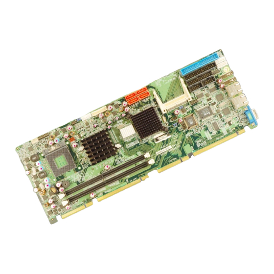
IEI Technology PCIE-9452 User Manual (274 pages)
Socket 479 Intel Core 2 Duo PICMG 1.3 CPU Card DDR2, SATA II, Dual PCIe GbE, PCIe Expansion
Brand:
IEI Technology
| Category:
Computer Hardware
| Size: 8 MB
Table of Contents
Table of Contents
5
1 Introduction
21
Introduction
22
PCIE-9452 Benefits
22
PCIE-9452 Features
22
Figure 1-1: PCIE-9452 Overview [Front View]
23
Pcie-9452 Overview
23
PCIE-9452 Overview Photo
23
PCIE-9452 Peripheral Connectors and Jumpers
23
Technical Specifications
24
Table 1-1: Technical Specifications
26
2 Detailed Specifications
27
Dimensions
28
Board Dimensions
28
Figure 2-1: PCIE-9452 Dimensions (MM)
28
Overview
28
Data Flow
29
External Interface Panel Dimensions
29
Figure 2-2: External Interface Panel Dimensions (MM)
29
Figure 2-3: Data Flow Block Diagram
30
Table 2-1: Processor Features
31
Intel ® 945Gm Northbridge Chipset
32
Intel ® 945GM Overview
32
Table 2-2: Supported Processors
32
Figure 2-4: 240-Pin DDR2 DIMM Socket
33
Figure 2-5: Pcie X16 Golden Fingers
34
Intel 945GM Analog CRT Support
35
Intel 945GM LVDS Support
35
Intel ® 945GM Integrated Graphics
35
Intel 945GM SDVO Support
36
Intel 945GM TV out Support
36
Intel ® 945GM Direct Media Interface (DMI)
36
Intel ® ICH7R Audio Codec '97 Controller
37
Intel ® ICH7R Overview
37
Intel ® Ich7R Southbridge Chipset
37
Intel ® ICH7R IDE Interface
38
Table 2-3: Supported HDD Specifications
38
Intel ® ICH7R Low Pin Count (LPC) Interface
39
Intel ® ICH7R PCI Interface
39
Intel ® ICH7R Real Time Clock
39
Intel ® ICH7R SATA Controller
39
Backplane USB Implementation
40
Figure 2-6: Onboard USB Implementation
40
Intel ICH7R USB Controller Overview
40
Intel ® ICH7R USB Controller
40
PCIE-9452 USB Implementation
40
Intel ICH7R Pcie Bus Overview
41
Intel ® ICH7R Pcie Bus
41
Pcie X4 Expansion Options
41
Intel ® 945GM Memory Support
33
Intel ® 945GM Pcie X16
34
Pcie X16 Bus Overview
34
Pcie X16 Bus Specifications
34
Pcie X16 Expansion Options
34
Compatible Processors
31
Compatible Processor Overview
31
Supported Processors
31
Figure 2-7: I/O Golden Finger
41
Figure 2-9: Broadcom PCI Gbe Controllers
42
Figure 2-10: BIOS Chipset
44
Figure 2-11: Super I/O Chipset
44
Table 2-4: Power Consumption
48
IEI Chassis
49
Figure 2-8: Pcie X4 Golden Finger
42
Super I/O 16C550 Uarts
45
Super I/O Enhanced Hardware Monitor
45
Super I/O Fan Speed Controller
45
Super I/O LPC Interface
45
Environmental and Power Specifications
46
System Monitoring
46
Operating Temperature and Temperature Control
47
Power Consumption
48
Super I/O Keyboard Controller
46
Super I/O Parallel Port
46
Expansion Options
48
Expansion Options Overview
48
IEI Expansion PICMG 1.3 Backplanes
48
Pcie Gbe Ethernet
42
Lpc Bus Components
43
LPC Bus Overview
43
BIOS Chipset
43
Super I/O Chipset
44
Table 2-5: Compatible IEI PICMG 1.3 Backplanes
49
Table 2-6: Compatible IEI Chassis
51
3 Unpacking
53
Anti-Static Precautions
54
Unpacking
54
Unpacking Precautions
54
Unpacking Checklist
55
Package Contents
55
Table 3-1: Package List Contents
56
Optional Items
57
Table 3-2: Optional Items
58
4 Connector Pinouts
59
Figure 4-1: Connector and Jumper Locations
60
Peripheral Interface Connectors
60
PCIE-9452 Layout
60
Peripheral Interface Connectors
61
External Interface Panel Connectors
62
Internal Peripheral Connectors
62
ATX Power Supply Enable Connector
62
Table 4-1: Peripheral Interface Connectors
62
Table 4-2: Rear Panel Connectors
62
Table 4-3: ATX Power Supply Enable Connector Pinouts
64
Figure 4-3: Audio Connector Pinouts (10-Pin)
65
Figure 4-4: Panel Backlight Connector Pinout Locations
66
Compact Flash Socket
67
Table 4-5: Panel Backlight Connector Pinouts
67
Figure 4-5: CF Card Socket Location
68
Table 4-6: CF Card Socket Pinouts
69
Digital Input/Output (DIO) Connector
70
Figure 4-6: DIO Connector Connector Locations
70
Fan Connector (+12V)
71
Figure 4-7: +12V Fan Connector Location
71
Table 4-7: DIO Connector Connector Pinouts
71
Figure 4-8: 34-Pin FDD Connector Location
72
Floppy Disk Connector (34-Pin)
72
Table 4-8: +12V Fan Connector Pinouts
72
Front Panel Connector (14-Pin)
73
Table 4-9: 34-Pin FDD Connector Pinouts
73
Figure 4-9: Front Panel Connector Pinout Locations
74
Table 4-10: Front Panel Connector Pinouts
74
IDE Connector(40-Pin)
75
Figure 4-10: Secondary IDE Device Connector Locations
76
Figure 4-11: Infrared Connector Pinout Locations
77
Infrared Interface Connector (5-Pin)
77
Table 4-11: Secondary IDE Connector Pinouts
77
Keyboard Connector
78
Table 4-12: Infrared Connector Pinouts
78
Figure 4-12: Keyboard Connector Location
79
LVDS LCD Connector
79
Table 4-13: Keyboard Connector Pinouts
79
Figure 4-13: LVDS LCD Connector Pinout Locations
80
Mouse Connector
81
Table 4-14: LVDS LCD Port Connector Pinouts
81
Figure 4-14: Mouse Connector Location
82
Parallel Port Connector
82
Table 4-15: Mouse Connector Pinouts
82
Figure 4-15: Parallel Port Connector Location
83
SATA Drive Connectors
84
Table 4-4: Audio Connector Pinouts (10-Pin)
65
Backlight Inverter Connector
66
Figure 4-2: ATX Power Supply Enable Connector Location
63
Audio Connector (9-Pin)
64
Table 4-16: Parallel Port Connector Pinouts
84
Table 4-17: SATA Drive Connector Pinouts
85
Figure 4-16: SATA Drive Connector Locations
85
Figure 4-17: COM1 and COM2 Connector Pinout Locations
86
Table 4-18: COM1 and COM2
87
TV out Connector
87
Figure 4-18: TV Connector Pinout Locations
88
Table 4-19: TV Port Connector Pinouts
88
Figure 4-19: USB Connector Pinout Locations
89
Table 4-20: USB Port Connector Pinouts
89
External Peripheral Interface Connector Panel
90
Figure 4-20: PCIE-9452 External Peripheral Interface Connector
90
LAN Connectors
90
Table 4-21: LAN Pinouts
90
Figure 4-21: RJ-45 Ethernet Connector
91
Table 4-22: RJ-45 Ethernet Connector Leds
91
USB Connector
91
VGA Connector
92
USB Connectors (Internal)
88
Serial Port Connector (Com1And COM2)
86
Table 4-23: USB Port Pinouts
92
Figure 4-22: VGA Connector
92
Table 4-24: VGA Connector Pinouts
93
5 Installation
95
Anti-Static Precautions
96
Installation Considerations
97
Installation Notices
97
Installation Checklist
98
Cpu, Cpu Cooling Kit and DIMM Installation
99
Socket 479 CPU Installation
99
Figure 5-1: Make Sure the CPU Socket Retention Screw Is Unlocked
100
Figure 5-2: Lock the CPU Socket Retention Screw
101
Cooling Kit CF-479B-RS Installation
102
Figure 5-3: IEI CF-479B-RS Cooling Kit
102
Figure 5-5: Connect the Cooling Fan Cable
103
Figure 5-4: Cooling Kit Support Bracket
103
Figure 5-6: Installing a DIMM
104
CF Card Installation
105
Figure 5-7: CF Card Installation
106
Figure 5-8: Jumper Locations
107
Jumper Settings
107
Table 5-1: Jumpers
107
Table 5-2: CF Card Setup Jumper Settings
108
Clear CMOS Jumper
109
Figure 5-9: CF Card Setup Jumper Location
109
Figure 5-10: Clear CMOS Jumper
110
Table 5-3: Clear CMOS Jumper Settings
110
LVDS Voltage Selection
111
Table 5-4: LVDS Voltage Selection Jumper Settings
111
Airflow
112
Chassis Installation
112
Figure 5-11: LVDS Voltage Selection Jumper Pinout Locations
112
Backplane Installation
113
CPU Card Installation
113
IDE Cable Connection
114
Internal Peripheral Device Connections
114
Peripheral Device Cables
114
Table 5-5: IEI Provided Cables
114
Channel Audio Kit Installation
115
Figure 5-12: IDE Cable Connection
115
Figure 5-13: 5.1 Channel Audio Kit
116
Channel Audio Kit Installation
117
Figure 5-14: 5.1 Channel Audio Kit
118
Parallel Port Cable
118
Figure 5-15: LPT Cable Connection
119
Dual RS-232 Cable Connection
120
Figure 5-16: Connect the LPT Device
120
Figure 5-17: Dual RS-232 Cable Installation
121
USB Cable (Dual Port)
121
Figure 5-18: Dual USB Cable Connection
122
SATA Drive Connection
122
Figure 5-19: SATA Drive Cable Connection
123
Figure 5-20: SATA Power Drive Connection
124
Wafer-To-PS/2 Cable (Keyboard/Mouse Installation)
124
External Peripheral Interface Connection
125
Figure 5-21: Keyboard/Mouse Cable Connection
125
Figure 5-22: LAN Connection
126
LAN Connection (Single Connector)
126
Figure 5-23: USB Device Connection
127
USB Device Connection (Single Connector)
127
VGA Monitor Connection
128
CF Card Setup
108
DIMM Installation
104
Figure 5-24: VGA Connector
128
6 Ami Bios
129
Introduction
130
Starting Setup
130
Using Setup
130
Getting Help
131
Unable to Reboot after Configuration Changes
131
BIOS Menu Bar
131
Table 6-1: BIOS Navigation Keys
131
Main
132
Advanced
133
CPU Configuration
134
Menu 3: CPU Configuration
135
IDE Configuration
136
IDE Master, IDE Slave
137
Menu 5: IDE Master and IDE Slave Configuration
138
Floppy Configuration
143
Super IO Configuration
144
Hardware Health Configuration
147
Menu 8: Hardware Health Configuration
148
ACPI Configuration
153
General ACPI Configuration
154
APM Configuration
155
Menu 11:Advanced Power Management Configuration
156
MPS Configuration
159
Remote Access Configuration
160
USB Configuration
164
Pci/Pnp
166
Menu 15: Pci/Pnp Configuration
167
Boot
172
Boot Settings Configuration
172
Menu 17: Boot Settings Configuration
173
Boot Device Priority
175
Menu 18: Boot Device Priority Settings
176
Hard Disk Drives
177
Removable Drives
178
Menu 20: Removable Drives
179
CD/DVD Drives
180
Menu 21: CD/DVD Drives
181
Security
182
Chipset
183
Northbridge Configuration
184
Menu 24:Northbridge Chipset Configuration
185
Video Function Configuration
189
Figure 6-1: Video Function Configuration
190
Southbridge Chipset Configuration
194
Exit
196
7 Driver Installation
199
Available Software Drivers
200
Driver CD Auto-Run
200
Figure 7-1: Introduction Screen
201
Chipset Driver Installation
202
Figure 7-2: Available Drivers
202
Figure 7-3: Chipset Driver Installation Program
203
Figure 7-4: Chipset Driver Installation Welcome Screen
204
Figure 7-5: Chipset Driver Installation License Agreement
205
Figure 7-6: Chipset Driver Readme File Information
206
Figure 7-7: Chipset Driver Installation Complete
207
Figure 7-15: GMA Driver Installation Complete
213
Figure 7-16: Access Windows Control Panel
214
Figure 7-17: Double Click the System Icon
215
Figure 7-18: Double Click the Device Manager Tab
215
Figure 7-19: Device Manager List
216
Figure 7-23: 4-AUDIO\AC-Kit883Hd\Windows Folder
219
Figure 7-24: HD Audio Driver Setup Extracting Files
220
Figure 7-25: HD Audio Driver Setup Welcome Screen
221
Figure 7-26: HD Audio Driver Installation Complete
222
BIOS Setup
223
Driver Installation
223
Realtek Ac`97 Audio Driver (Alc665) Installation
223
Figure 7-20: Search for Suitable Driver
217
Figure 7-22: Location Browsing Window
218
Figure 7-21: Locate Driver Files
218
Realtek Hd Audio Driver (Alc883) Installation
219
BIOS Setup
219
Driver Installation
219
Intel Graphics Media Accelerator Driver
207
Figure 7-8: Select the Operating System
208
Figure 7-9: VGA Driver
209
Figure 7-10: GMA Driver Readme File
210
Figure 7-11: GMA Driver File Extraction
210
Figure 7-12: GMA Driver Installation Welcome Screen
211
Figure 7-14: GMA Driver Installing Notice
212
Figure 7-13: GMA Driver License Agreement
212
Broadcom LAN Driver (for Gbe LAN) Installation
213
Figure 7-28: AC`97 Audio Driver Install Shield Wizard Starting
224
Figure 7-27: CD 4-AUDIO\AC-Kit08R\Windows Folder
224
Figure 7-29: AC`97 Audio Driver Setup Preparation
225
Figure 7-30: AC`97 Audio Driver Welcome Screen
226
Figure 7-31: AC`97 Audio Driver Software Configuration
227
Figure 7-32: AC`97 Audio Driver Digital Signal
228
Figure 7-33: AC`97 Audio Driver Installation Begins
229
Figure 7-34: AC`97 Audio Driver Installation Complete
230
Figure 7-35: SATA RAID Driver Installation Program
231
Intel Matrix Storage Manager Installation
231
Figure 7-36: SATA RAID Setup Program Icon
232
Figure 7-37: Installshield Wizard Setup Screen
232
Figure 7-38: Matrix Storage Manager Setup Screen
233
Figure 7-39: Matrix Storage Manager Welcome Screen
233
Figure 7-40: Matrix Storage Manager Warning Screen
234
Figure 7-41: Matrix Storage Manager License Agreement
234
Figure 7-42: Matrix Storage Manager Readme File
235
Figure 7-43: Matrix Storage Manager Setup Complete
236
Abios Options
237
Bdio Interface
243
Dio Interface Introduction
244
Dio Connector Pinouts
244
Assembly Language Samples
244
Enable the DIO Input Function
244
Enable the DIO Output Function
245
Cwatchdog Timer
247
Daddress Mapping
251
Address Map
252
St Mb Memory Address Map
252
D.1 Addres Map
252
Irq Mapping Table
253
Dma Channel Assignments
253
Intel® Matrix Storage Manager
255
Introduction
256
Precautions
256
E.1 I Ntroduction
256
Features and Benefits
257
Accessing the Intel® Matrix Storage Manager
257
Raid Configuration
258
Creating a RAID Volume
258
E.4 RAID C ONFIGURATION E.4.1 Creating a RAID Volume
258
Deleting a RAID Volume
263
Resetting a Disk to Non-RAID
265
Exiting the Matrix Storage Manager
268
Findex
269
Advertisement
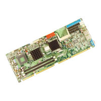
IEI Technology PCIE-9452 Quick Installation Manual (7 pages)
PICMG 1.3 Socket M Intel Core 2 Duo CPU Card with VGA, Dual PCIe GbE, SATA and USB2.0
Brand:
IEI Technology
| Category:
Computer Hardware
| Size: 0 MB
Table of Contents
Specifications
2
Ordering Information
3
Jumpers Setting and Connectors
3
Board Layout: Jumper and Connector Locations
7
Advertisement
Related Products
IEI Technology PCIE-9152
IEI Technology PCIE-Q350
IEI Technology PCIE-H610
IEI Technology PCIE-Q470
IEI Technology PCIE-Q370-R11
IEI Technology PCIE-Q170-R10
IEI Technology PCIE-9650
IEI Technology PCIE-Q170-i2-R10
IEI Technology PCISA-LX
IEI Technology PCISA-BT-E38451
IEI Technology Categories
Motherboard
Touch Panel
Computer Hardware
Single board computers
Desktop
More IEI Technology Manuals
Login
Sign In
OR
Sign in with Facebook
Sign in with Google
Upload manual
Upload from disk
Upload from URL