Advertisement
Quick Links
Download this manual
See also:
User Manual
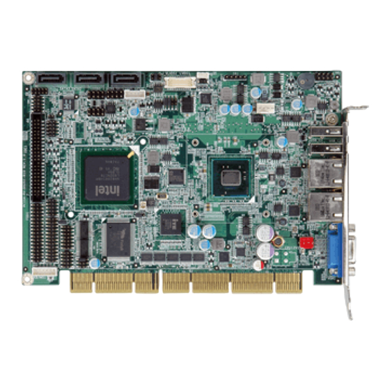
Half-Size PCISA CPU Card with Intel® Atom™
D425/N455/D525, DDR3, VGA/LVDS, Dual PCIe GbE, USB
2.0, four COM, three SATA II, Audio and RoHS
PCISA-PV-D4251/N4551/D5251
Quick Installation Guide
Package Contents:
PCISA-PV-D4251/N4551/D5251 package includes the following items:
1 x PCISA-PV-D4251/N4551/D5251 Single Board Computer
1 x USB Cable
3 x SATA Cable
1 x LPT/RS232 Cable
1 x Audio cable
1 x Mini Jumper Pack
1 x QIG (Quick Installation Guide)
1 x Utility CD
1 x One Key recovery CD
Version 1.0
Oct. 13, 2010
©2006 Copyright
All rights reserved.
1
Advertisement

Subscribe to Our Youtube Channel
Related Manuals for IEI Technology PCISA-PV-N4551


Summary of Contents for IEI Technology PCISA-PV-N4551
-
Page 1: Quick Installation Guide
Half-Size PCISA CPU Card with Intel® Atom™ D425/N455/D525, DDR3, VGA/LVDS, Dual PCIe GbE, USB 2.0, four COM, three SATA II, Audio and RoHS PCISA-PV-D4251/N4551/D5251 Quick Installation Guide Version 1.0 Oct. 13, 2010 Package Contents: PCISA-PV-D4251/N4551/D5251 package includes the following items: 1 x PCISA-PV-D4251/N4551/D5251 Single Board Computer 1 x USB Cable 3 x SATA Cable... -
Page 2: Specifications
Specifications: CPU: Intel® Atom™ D525 dual-core processor (1.80GHz/1MB L2 cache) Intel® Atom™ D425 single-core processor (1.80GHz/512KB L2 cache) Intel® Atom™ N455 single-core processor (1.66GHz/512KB L2 cache) System Chipset: Intel® ICH8M BIOS: UEFI BIOS System Memory: One 204-pin 800MHz DDR3 SDRAM SO-DIMM Supported (System max:2GB) Ethernet: Dual PCIe GbE by Realtek RTL8111E, LAN1 supports ASF2.0... -
Page 3: Ordering Information
512KB L2 Cache, VGA/LVDS, Dual PCIe GbE, USB 2.0, 4 COM, 3 SATA II and audio, TPM, RoHS PCISA-PV-N4551-R10: Half-size PCISA CPU Card with Intel® Dual Core Atom™ N455 1.66GHz/ 512KB L2 Cache, VGA/LVDS, Dual PCIe GbE, USB 2.0, 4 COM, 3 SATA... - Page 4 PCISA-PV-N4551T-R10: Half-size PCISA CPU Card with Intel® Dual Core Atom™ N455 1.66GHz/ 512KB L2 Cache, VGA/LVDS, Dual PCIe GbE, USB 2.0, 4 COM, 3 SATA II and audio, TPM, RoHS 32200-000058-RS: FDD cable w/o bracket 19800-000075-RS: KB/MS cable with bracket 32200-000052-RS: IDE Cable 32102-000100-200-RS: SATA Power Cable 19FTS00032100-000001-RS: CPU Fan...
-
Page 5: Jumpers Setting And Connectors
Jumpers setting and Connectors: LABEL FUNCTION J_CMOS1 CMOS state setting jumper JCF1 CF Card Master/Slave jumper J_VLVDS1 LVDS1 Voltage Selection jumper PCIe Configuration Selection jumper RS232/422/485 Selection ATXCTL1 AT/ATX1 mode setting LVDS Panel Selection COM1 RS-232 COM2 RS-232/422/485 COM3,COM4 RS-232 Pin Header USB0_1,USB2_1 Internal USB Pin Header USB_C1,USB_C2 USB Port... - Page 6 JCF1 : Configure CF Card type J_CMOS1 : Clear CMOS Setup J_CMOS1 DESCRIPTION JCF1 DESCRIPTION Short 1-2 Keep CMOS Setup Open Slave Short 2-3 Clear CMOS Setup Short 1-2 Master J_VLVDS1 : Set The Panel Voltage JP1 : PCIe Configuration DESCRIPTION DESCRIPTION Short...
- Page 7 COM2 : Serial Port Connector (RS-232/422/485) PIN HEADER 2*7,14PIN, P:2.0mm DESCRIPTION DESCRIPTION -NDCDB -NDSRB NSINB -NRTSB NSOUTB -NCTSB -NDTRB -XRI2 TXD485+ TXD485- RXD485+ RXD485- COM3, COM4:RS-232 PIN HEADER 2*5,10PIN,180D,P:2.0mm PIN NO. DESCRIPTION PIN NO. DESCRIPTION NDSR3/4 NDCD3/4 NRX3/4 NRTS3/4 NTX3/4 NCTS3/4 NDTR3/4 NRI3/4...
- Page 8 F_PANEL1: PWR & RST Buttons and Indicators panel PIN DESCRIPTION PIN DESCRIPTION PWR_BTN+ PWR_LED+ PWRBTN Power LED PWR_BTN- PWR_LED- HDD_LED+ RESET+ RESET HDD_LED- RESET- LVDS1: LVDS Connector PIN NO. DESCRIPTION PIN NO. DESCRIPTION GND2 LVDSA_DATA0+ LVDSA_DATA0- LVDSA_DATA1+ LVDSA_DATA1- LVDSA_DATA2+ LVDSA_DATA2- LVDS_CLK+ LVDSA_CLK- L_DDC_DATA...
- Page 9 AUDIO1: Audio Module Connector BAT1 : Battery Connector PIN HEADER 2*5,10PIN, P:2.0mm DESCRIPTION PIN DESCRIPTION PIN DESCRIPTION BAT+ 1 SPEAKOUT_R 2 LINEIN_R BAT-(GND) 5 SPEAKOUT _L 6 LINEIN_L MICIN_R MICIN_L DIO1: Digital Input / Output Connector PIN DESCRIPTION PIN DESCRIPTION OUTPUT 3 OUTPUT 2 OUTPUT 1...
- Page 10 VGA1:D-SUB VGA,15PIN,90° ,P=2.29MM PIN NO. DESCRIPTION PIN NO. DESCRIPTION GREEN DISPLAY_GND BLUE 5VDDCDA 5VDDCLK LPT1: LPT PIN HEADER 2X13,26PIN,180° ° ° ° ,P=2.0MM PIN NO. DESCRIPTION PIN NO. DESCRIPTION -STB -AFD -ERR PTD0 -INIT PTD1 -SLIN PTD2 PTD3 PTD4 PTD5 PTD6 PTD7 -ACK...
- Page 11 Board Layout: Jumper and Connector Locations (Unit:mm)
- Page 12 Board Layout: Jumper and Connector Locations (Unit:mm)
Need help?
Do you have a question about the PCISA-PV-N4551 and is the answer not in the manual?
Questions and answers