Table of Contents
Advertisement
Quick Links
Advertisement
Table of Contents

Subscribe to Our Youtube Channel
Related Manuals for IEI Technology PCIE-H610


Summary of Contents for IEI Technology PCIE-H610
- Page 1 PCIE-H610 PICMG 1.3 CPU Card MODEL: PCIE-H610 Full-Size PICMG 1.3 CPU Card Supports 32nm LGA1155 Intel® Core™ i7/i5/i3/Pentium®/Celeron® CPU, Intel® H61 Chipset, DDR3, VGA, DVI-D, Dual Realtek PCIe GbE, USB 2.0, SATA 3Gb/s, HD Audio and RoHS User Manual Page i...
- Page 2 PCIE-H610 PICMG 1.3 CPU Card Revision Date Version Changes November 16, 2015 1.05 Updated Section 1.7: Technical Specifications August 25, 2015 1.04 Modified Section 3.2.15: Serial Port Connectors, RS-232 November 5, 2014 1.03 Modified LAN pinouts Updated Chapter 2: Packing List November 14, 2013 1.02...
- Page 3 PCIE-H610 PICMG 1.3 CPU Card Copyright COPYRIGHT NOTICE The information in this document is subject to change without prior notice in order to improve reliability, design and function and does not represent a commitment on the part of the manufacturer.
-
Page 4: Manual Conventions
PCIE-H610 PICMG 1.3 CPU Card Manual Conventions WARNING Warnings appear where overlooked details may cause damage to the equipment or result in personal injury. Warnings should be taken seriously. CAUTION Cautionary messages should be heeded to help reduce the chance of losing data or damaging the product. -
Page 5: Table Of Contents
PCIE-H610 PICMG 1.3 CPU Card Table of Contents 1 INTRODUCTION......................1 1.1 I ......................2 NTRODUCTION 1.2 M ....................2 ODEL ARIATIONS 1.3 F ........................3 EATURES 1.4 C ......................3 ONNECTORS 1.5 D ....................... 4 IMENSIONS 1.6 D ........................ 6 1.7 T... - Page 6 PCIE-H610 PICMG 1.3 CPU Card 3.2.10 I2C Connector....................27 3.2.11 Infrared Interface Connector ................. 27 3.2.12 Keyboard/Mouse Connector ................28 3.2.13 Parallel Port Connector ................29 3.2.14 SATA 3Gb/s Drive Connectors............... 30 3.2.15 Serial Port Connectors, RS-232..............31 3.2.16 Serial Port Connector, RS-422/485..............32 3.2.17 SMBus Connector ..................
- Page 7 PCIE-H610 PICMG 1.3 CPU Card 4.6.1 LAN Connection....................55 4.6.2 USB Device Connection (Single Connector) ........... 56 4.6.3 VGA Monitor Connection ................57 5 BIOS ..........................59 5.1 I ......................60 NTRODUCTION 5.1.1 Starting Setup....................60 5.1.2 Using Setup ...................... 60 5.1.3 Getting Help.....................
- Page 8 PCIE-H610 PICMG 1.3 CPU Card 6 SOFTWARE DRIVERS ....................96 6.1 A ................97 VAILABLE OFTWARE RIVERS 6.2 S ..................97 OFTWARE NSTALLATION 6.3 C ................99 HIPSET RIVER NSTALLATION 6.4 G ................102 RAPHICS RIVER NSTALLATION 6.5 LAN D ..................
- Page 9 PCIE-H610 PICMG 1.3 CPU Card List of Figures Figure 1-1: PCIE-H610 ........................2 Figure 1-2: Connectors ........................3 Figure 1-3: PCIE-H610 Dimensions (mm)..................4 Figure 1-4: External Interface Panel Dimensions (mm) ..............5 Figure 1-5: Data Flow Diagram......................6 Figure 3-1: Connectors and Jumpers..................17 Figure 3-2: Audio Connector Location ..................19 Figure 3-3: Battery Connector Location..................20...
- Page 10 PCIE-H610 PICMG 1.3 CPU Card Figure 4-2: Remove Protective Cover..................43 Figure 4-3: Insert the Socket LGA1155 CPU................44 Figure 4-4: Close the Socket LGA1155 ..................44 Figure 4-5: Cooling Kit Support Bracket ..................45 Figure 4-6: DIMM Installation.......................46 Figure 4-7: AT/ATX Power Mode Jumper Location..............48 Figure 4-8: Clear BIOS Jumper Location ...................49...
- Page 11 PCIE-H610 PICMG 1.3 CPU Card List of Tables Table 1-1: PCIE-H610 Model Variations..................2 Table 1-2: PCIE-H610 Specifications ....................9 Table 2-1: Packing List.........................13 Table 2-2: Optional Items......................15 Table 3-1: Peripheral Interface Connectors ................18 Table 3-2: Rear Panel Connectors ....................18 Table 3-3: Audio Connector Pinouts ..................19 Table 3-4: Battery Connector Pinouts ..................20...
- Page 12 PCIE-H610 PICMG 1.3 CPU Card Table 4-1: Jumpers ........................47 Table 4-2: AT/ATX Power Mode Jumper Settings ..............48 Table 4-3: Clear BIOS Jumper Settings..................48 Table 4-4: Wake-on LAN Jumper Settings .................49 Table 4-5: Wake-on LAN Jumper Pinouts ..................50 Table 5-1: BIOS Navigation Keys ....................61...
- Page 13 PCIE-H610 PICMG 1.3 CPU Card BIOS Menus BIOS Menu 1: Main ........................62 BIOS Menu 2: Advanced ......................63 BIOS Menu 3: ACPI Configuration ....................64 BIOS Menu 4: TPM Configuration ....................65 BIOS Menu 5: CPU Configuration ....................66 BIOS Menu 6: CPU Configuration ....................67 BIOS Menu 7: SATA Configuration .....................68...
-
Page 14: Introduction
PCIE-H610 PICMG 1.3 CPU Card Chapter Introduction Page 1... -
Page 15: Introduction
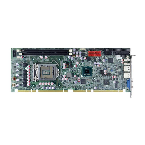
PCIE-H610 PICMG 1.3 CPU Card 1.1 Introduction Figure 1-1: PCIE-H610 The PCIE-H610 PICMG 1.3 CPU card is a Socket LGA1155 32nm Intel® Core™ i3/i5/i7/Pentium®/Celeron® processor platform that supports two 240-pin 1066/1333 MHz dual-channel DDR3/DDR3L DIMM modules up to 16.0 GB. -
Page 16: Features
Two Realtek PCIe Gigabit Ethernet connectors (LAN1 with ASF 2.0 support) Four SATA 3Gb/s connectors TPM V1.2 hardware security function supported by the TPM module High Definition Audio RoHS compliant 1.4 Connectors The connectors on the PCIE-H610 are shown in the figure below. Figure 1-2: Connectors Page 3... -
Page 17: Dimensions
PCIE-H610 PICMG 1.3 CPU Card 1.5 Dimensions The main dimensions of the PCIE-H610 are shown in the diagram below. Figure 1-3: PCIE-H610 Dimensions (mm) Page 4... -
Page 18: Figure 1-4: External Interface Panel Dimensions (Mm)
PCIE-H610 PICMG 1.3 CPU Card Figure 1-4: External Interface Panel Dimensions (mm) Page 5... -
Page 19: Data Flow
PCIE-H610 PICMG 1.3 CPU Card 1.6 Data Flow F igure 1-5 shows the data flow between the system chipset, the CPU and other components installed on the motherboard. Figure 1-5: Data Flow Diagram Page 6... -
Page 20: Technical Specifications
PCIE-H610 PICMG 1.3 CPU Card 1.7 Technical Specifications The PCIE-H610 technical specifications are listed below. Specification/Model PCIE-H610 PICMG 1.3 Form Factor LGA1155 Intel® Core™ i7/i5/i3/Pentium®/Celeron® CPU CPU Supported Intel® H61 Memory Two 240-pin 1333/1066 MHz dual-channel unbuffered DDR3/DDR3L (1.35V) SDRAM DIMMs support (system max. 16.0 GB) Graphics Engine Intel®... - Page 21 PCIE-H610 PICMG 1.3 CPU Card One VGA integrated in the Intel® H61 (rear I/O) Display Output One DVI-D integrated in the Intel® H61 (via 26-pin header to the DVI-D/USB kit; DVI model only) Two RJ-45 GbE ports Ethernet One 4-pin wafer connector...
-
Page 22: Table 1-2: Pcie-H610 Specifications
PCIE-H610 PICMG 1.3 CPU Card 338 mm x 126 mm Dimensions 1200 g / 420 g Weight (GW/NW) Table 1-2: PCIE-H610 Specifications Page 9... -
Page 23: Packing List
PCIE-H610 PICMG 1.3 CPU Card Chapter Packing List Page 10... -
Page 24: Anti-Static Precautions
Only handle the edges of the PCB: Don't touch the surface of the motherboard. Hold the motherboard by the edges when handling. 2.2 Unpacking Precautions When the PCIE-H610 is unpacked, please do the following: Follow the anti-static guidelines above. Make sure the packing box is facing upwards when opening. -
Page 25: Packing List
If any of the components listed in the checklist below are missing, do not proceed with the installation. Contact the IEI reseller or vendor the PCIE-H610 was purchased from or contact an IEI sales representative directly by sending an email to ales@ieiworld.com. -
Page 26: Optional Items
PCIE-H610 PICMG 1.3 CPU Card Quantity Item and Part Number Image One Key Recovery CD Utility CD Quick Installation Guide Table 2-1: Packing List 2.4 Optional Items The following are optional components which may be separately purchased: Item and Part Number... - Page 27 PCIE-H610 PICMG 1.3 CPU Card Item and Part Number Image LPT cable (P/N: 19800-000049-RS) 7.1-channel HD audio kit with Realtek ALC892 audio codec supporting dual audio stream (P/N: AC-KIT-892HD-R10) Infineon TPM module (P/N: TPM-IN01-R11) LGA1155/LGA1156 cooler kit (1U chassis compatible,...
-
Page 28: Table 2-2: Optional Items
PCIE-H610 PICMG 1.3 CPU Card Item and Part Number Image Intel® Core™ i5-2390T processor (LGA1155, dual core 2.7 GHz, 3M cache, 35W, compatible with CF-1156C-RS CPU cooler kit) (P/N: CPU-DT-i5-2390T) Intel® Core™ i3-2120T processor (LGA1155, dual core 2.6 GHz, 3M cache, 35W, compatible with CF-1156C-RS... -
Page 29: Connectors
PCIE-H610 PICMG 1.3 CPU Card Chapter Connectors Page 16... -
Page 30: Peripheral Interface Connectors
PCIE-H610 PICMG 1.3 CPU Card 3.1 Peripheral Interface Connectors This chapter details all the jumpers and connectors. 3.1.1 PCIE-H610 Layout The figures below show all the connectors and jumpers. Figure 3-1: Connectors and Jumpers 3.1.2 Peripheral Interface Connectors The table below lists all the connectors on the board. -
Page 31: External Interface Panel Connectors
PCIE-H610 PICMG 1.3 CPU Card Connector Type Label Fan connector (CPU) 4-pin wafer CPU_FAN1 Floppy disk drive connector 34-pin box header FDD1 Front panel connector 14-pin header F_PANEL1 I2C connector 4-pin wafer I2C_1 Infrared connector 5-pin header Keyboard and mouse connector... -
Page 32: Internal Peripheral Connectors
PCIE-H610 PICMG 1.3 CPU Card 3.2 Internal Peripheral Connectors The section describes all of the connectors on the PCIE-H610. 3.2.1 Audio Kit Connector CN Label: J_AUDIO1 10-pin header CN Type: CN Location: See Figure 3-2 CN Pinouts: See Table 3-3 This connector connects to an external audio kit. -
Page 33: Battery Connector
PCIE-H610 PICMG 1.3 CPU Card 3.2.2 Battery Connector CAUTION: Risk of explosion if battery is replaced by an incorrect type. Only certified engineers should replace the on-board battery. Dispose of used batteries according to instructions and local regulations. CN Label:... -
Page 34: Cpu Power Input Connector
PCIE-H610 PICMG 1.3 CPU Card 3.2.3 CPU Power Input Connector CN Label: CPU12V1 4-pin Molex power connector CN Type: CN Location: See Figure 3-4 CN Pinouts: See Table 3-5 The connector supports the 12V power supply. Figure 3-4: ATX Power Connector Pinout Location... -
Page 35: Digital I/O Connector
PCIE-H610 PICMG 1.3 CPU Card Figure 3-5: DDR3 DIMM Slot Locations 3.2.5 Digital I/O Connector CN Label: DIO1 CN Type: 10-pin header CN Location: See Figure 3-6 CN Pinouts: See Table 3-6 The digital I/O connector provides programmable input and output for external devices. -
Page 36: Dvi-D Connector (Dvi Model Only)
PCIE-H610 PICMG 1.3 CPU Card Description Description Input 3 Input 2 Input 1 Input 0 Table 3-6: Digital I/O Connector Pinouts 3.2.6 DVI-D Connector (DVI Model Only) CN Label: DVI1 CN Type: 26-pin header CN Location: See Figure 3-7 CN Pinouts:... -
Page 37: Fan Connector (Cpu)
PCIE-H610 PICMG 1.3 CPU Card Description Description CK_DVI_DATA1 CK_DVI_CLK# CK_DVI_CLK Table 3-7: DVI-D Connector Pinouts 3.2.7 Fan Connector (CPU) CN Label: CPU_FAN1 4-pin wafer CN Type: CN Location: See Figure 3-8 CN Pinouts: See Table 3-8 The fan connector attaches to a CPU cooling fan. -
Page 38: Floppy Disk Drive Connector
PCIE-H610 PICMG 1.3 CPU Card 3.2.8 Floppy Disk Drive Connector CN Label: FDD1 34-pin header CN Type: CN Location: See Figure 3-9 CN Pinouts: See Table 3-9 The floppy disk drive connector is connected to a floppy disk drive. Figure 3-9: Floppy Disk Location... -
Page 39: Front Panel Connector
PCIE-H610 PICMG 1.3 CPU Card Description Description RDATA- SIDE1- DSKCHG- Table 3-9: Floppy Disk Pinouts 3.2.9 Front Panel Connector CN Label: F_PANEL1 14-pin header CN Type: CN Location: See Figure 3-10 CN Pinouts: See Table 3-10 The front panel connector connects to the indicator LEDs and buttons on the computer's front panel. -
Page 40: I2C Connector
PCIE-H610 PICMG 1.3 CPU Card 3.2.10 I2C Connector CN Label: I2C_1 4-pin wafer CN Type: CN Location: See Figure 3-11 CN Pinouts: See Table 3-11 The I2C connector is for system debug. Figure 3-11: I2C Connector Location Description +5VS PCH_GP38_PU... -
Page 41: Keyboard/Mouse Connector
PCIE-H610 PICMG 1.3 CPU Card Figure 3-12: Infrared Connector Location Description IR-RX IR-TX Table 3-12: Infrared Connector Pinouts 3.2.12 Keyboard/Mouse Connector CN Label: KB_MS1 CN Type: 6-pin wafer CN Location: See Figure 3-13 CN Pinouts: See Table 3-13 The keyboard/mouse connector connects to a PS/2 Y-cable that can be connected to a PS/2 keyboard and mouse. -
Page 42: Parallel Port Connector
PCIE-H610 PICMG 1.3 CPU Card Description +5 VCC Mouse Data Mouse Clock Keyboard Data Keyboard Clock GROUND Table 3-13: Keyboard/Mouse Connector Pinouts 3.2.13 Parallel Port Connector CN Label: LPT1 CN Type: 26-pin box header CN Location: See Figure 3-14 CN Pinouts:... -
Page 43: Sata 3Gb/S Drive Connectors
PCIE-H610 PICMG 1.3 CPU Card Description Description PPD3 PPD4 PPD5 PPD6 PPD7 BUSY SLCT Table 3-14: Parallel Port Connector Pinouts 3.2.14 SATA 3Gb/s Drive Connectors CN Label: SATA1, SATA2, SATA3, SATA4 CN Type: 7-pin SATA drive connector CN Location: See Figure 3-15... -
Page 44: Serial Port Connectors, Rs-232
PCIE-H610 PICMG 1.3 CPU Card Description Description Table 3-15: SATA 3Gb/s Drive Connector Pinouts 3.2.15 Serial Port Connectors, RS-232 CN Label: COM1, COM2 10-pin box header CN Type: CN Location: See Figure 3-16 CN Pinouts: See Table 3-16 Each of these connectors provides RS-232 connections. -
Page 45: Serial Port Connector, Rs-422/485
PCIE-H610 PICMG 1.3 CPU Card 3.2.16 Serial Port Connector, RS-422/485 CN Label: COM3 4-pin wafer CN Type: CN Location: See Figure 3-17 CN Pinouts: See Table 3-17 This connector provides RS-422 or RS-485 communications. Figure 3-17: RS-422/485 Connector Location Description... -
Page 46: Smbus Connector
PCIE-H610 PICMG 1.3 CPU Card 3.2.17 SMBus Connector CN Label: SMBUS_1 4-pin wafer CN Type: CN Location: See Figure 3-18 CN Pinouts: See Table 3-19 The SMBus (System Management Bus) connector provides low-speed system management communications. Figure 3-18: SMBus Connector Location... -
Page 47: Tpm Connector
PCIE-H610 PICMG 1.3 CPU Card Figure 3-19: SPI Connector Location Description Description SPI_VCC SPI_CS0 SPI_CLK SPI_MISO SPI_MOSI Table 3-20: SPI Connector Pinouts 3.2.19 TPM Connector CN Label: TPM1 20-pin header CN Type: CN Location: See Figure 3-20 CN Pinouts: See Table 3-21 The TPM connector connects to a TPM module. -
Page 48: Usb Connectors
PCIE-H610 PICMG 1.3 CPU Card Description Description ERAME# RESRT# SMB_CLK SMB_DATA SB3V SERIRQ PM_SUS_STAT# DRQ# Table 3-21: TPM Connector Pinouts 3.2.20 USB Connectors CN Label: USB1, USB2 CN Type: 8-pin header CN Location: See Figure 3-21 CN Pinouts: See Table 3-22 The USB connectors connect to USB devices. -
Page 49: External Peripheral Interface Connector Panel
RJ-45 CN Location: See Figure 3-22 CN Pinouts: See Figure 3-23 and Table 3-23 The PCIE-H610 is equipped with two built-in RJ-45 Ethernet controllers. Each controller can connect to the LAN through one RJ-45 LAN connector. Description Description MDIA3- MDIA2+... -
Page 50: Usb Connectors
CN Type: USB port CN Location: See Figure 3-22 See Table 3-25 CN Pinouts: The PCIE-H610 has two external USB 2.0 ports. The ports connect to both USB 2.0 and USB 1.1 devices. Description DATA- DATA+ GROUND Table 3-25: USB Port Pinouts 3.3.3 VGA Connector... -
Page 51: Figure 3-24: Vga Connector
PCIE-H610 PICMG 1.3 CPU Card The VGA connector connects to a monitor that accepts a standard VGA input. Description Description GREEN BLUE VGAVCC DDCDAT HSYNC VSYNC DDCCLK Table 3-26: VGA Connector Pinouts Figure 3-24: VGA Connector Page 38... -
Page 52: Installation
PCIE-H610 PICMG 1.3 CPU Card Chapter Installation Page 39... -
Page 53: Anti-Static Precautions
Electrostatic discharge (ESD) can cause serious damage to electronic components, including the PCIE-H610. Dry climates are especially susceptible to ESD. It is therefore critical that whenever the PCIE-H610 or any other electrical component is handled, the following anti-static precautions are strictly adhered to. - Page 54 This helps to prevent potential ESD damage. Turn all power to the PCIE-H610 off: When working with the PCIE-H610, make sure that it is disconnected from all power supplies and that no electricity is being fed into the system.
-
Page 55: Socket Lga1155 Cpu Installation
PCIE-H610 PICMG 1.3 CPU Card 4.2.1 Socket LGA1155 CPU Installation WARNING: CPUs are expensive and sensitive components. When installing the CPU please be careful not to damage it in anyway. Make sure the CPU is installed properly and ensure the correct cooling kit is properly installed. -
Page 56: Figure 4-2: Remove Protective Cover
PCIE-H610 PICMG 1.3 CPU Card Figure 4-2: Remove Protective Cover Step 3: Inspect the CPU socket. Make sure there are no bent pins and make sure the socket contacts are free of foreign material. If any debris is found, remove it with compressed air. -
Page 57: Figure 4-3: Insert The Socket Lga1155 Cpu
PCIE-H610 PICMG 1.3 CPU Card Figure 4-3: Insert the Socket LGA1155 CPU Step 8: Close the CPU socket. Close the load plate and pull the load lever back a little to have the load plate be able to secure to the knob. Engage the load lever by pushing it back to its original position (Figure 4-4). -
Page 58: Socket Lga1155 Cooling Kit Installation
PCIE-H610 PICMG 1.3 CPU Card 4.2.2 Socket LGA1155 Cooling Kit Installation The cooling kit can be bought from IEI. The cooling kit has a heatsink and fan. WARNING: Do not wipe off (accidentally or otherwise) the pre-sprayed layer of thermal paste on the bottom of the heat sink. The thermal paste between the CPU and the heat sink is important for optimum heat dissipation. -
Page 59: Dimm Installation
PCIE-H610 PICMG 1.3 CPU Card Step 5: Connect the fan cable. Connect the cooling kit fan cable to the fan connector on the PCIE-H610. Carefully route the cable and avoid heat generating chips and fan blades. 4.2.3 DIMM Installation To install a DIMM, please follow the steps below and refer to Figure 4-6. -
Page 60: Jumper Settings
PCIE-H610 PICMG 1.3 CPU Card 4.3 Jumper Settings NOTE: A jumper is a metal bridge used to close an electrical circuit. It consists of two or three metal pins and a small metal clip (often protected by a plastic cover) that slides over the pins to connect them. -
Page 61: Clear Cmos Jumper
PCIE-H610 PICMG 1.3 CPU Card The AT/ATX Power Select jumper specifies the systems power mode as AT or ATX. Setting Description Closed ATX power (Default) Open AT power Table 4-2: AT/ATX Power Mode Jumper Settings Figure 4-7: AT/ATX Power Mode Jumper Location 4.3.2 Clear CMOS Jumper... -
Page 62: Wake-On Lan Jumper
PCIE-H610 PICMG 1.3 CPU Card Figure 4-8: Clear BIOS Jumper Location 4.3.3 Wake-on LAN Jumper CN Label: JLAN_PWR1 CN Type: 6-pin header CN Location: See Figure 4-9 CN Pinouts: See Table 4-4 The Wake-on LAN jumper allows the user to enable or disable the Wake-on LAN (WOL) function. -
Page 63: Chassis Installation
The PCIE-H610 must be installed in a chassis with ventilation holes on the sides allowing airflow to travel through the heat sink surface. In a system with an individual power supply unit, the cooling fan of a power supply can also help generate airflow through the board surface. -
Page 64: Dual Rs-232 Cable With Slot Bracket
PCIE-H610 PICMG 1.3 CPU Card 4.5.1 Dual RS-232 Cable with Slot Bracket The dual RS-232 cable slot connector consists of two connectors attached to two independent cables. Each cable is then attached to a D-sub 9 male connector that is mounted onto a slot. -
Page 65: Dvi-D/Usb Kit Installation (Dvi Model Only)
4.5.2 DVI-D/USB Kit Installation (DVI Model Only) The DVI-D/USB kit, consisting of one DVI-D and four USB ports, connects to the DVI-D and USB connectors on the PCIE-H610. To install the DVI-D/USB kit, please follow the steps below. Step 1: Connect the cables to the DVI-D/USB kit. -
Page 66: Sata Drive Connection
PCIE-H610 PICMG 1.3 CPU Card 4.5.3 SATA Drive Connection The PCIE-H610 is shipped with four SATA drive cables. To connect the SATA drives to the connectors, please follow the steps below. Step 1: Locate the connectors. The locations of the SATA drive connectors are shown in Chapter 3. -
Page 67: Usb Cable (Dual Port) With Slot Bracket
PCIE-H610 PICMG 1.3 CPU Card Figure 4-13: SATA Power Drive Connection 4.5.4 USB Cable (Dual Port) with Slot Bracket The PCIE-H610 is shipped with a dual port USB 2.0 cable. To connect the USB cable connector, please follow the steps below. Step 1: Locate the connectors. -
Page 68: External Peripheral Interface Connection
Step 3: Insert the cable connectors. Once the cable connectors are properly aligned with the USB connectors on the PCIE-H610, connect the cable connectors to the on-board connectors. See Figure 4-14. Figure 4-14: Dual USB Cable Connection Step 4: Attach the bracket to the chassis. The USB 2.0 connectors are attached to a bracket. -
Page 69: Usb Device Connection (Single Connector)
RJ-45 connector into the on-board RJ-45 connector. 4.6.2 USB Device Connection (Single Connector) There is one external USB 2.0 connector. The connector is perpendicular to the PCIE-H610. To connect a USB 2.0 or USB 1.1 device, please follow the instructions below. Step 1: Located the USB connector. -
Page 70: Vga Monitor Connection
4.6.3 VGA Monitor Connection The PCIE-H610 has a single female DB-15 connector on the external peripheral interface panel. The DB-15 connector is connected to a CRT or VGA monitor. To connect a monitor to the PCIE-H610, please follow the instructions below. -
Page 71: Figure 4-17: Vga Connector
PCIE-H610 PICMG 1.3 CPU Card Figure 4-17: VGA Connector Step 4: Secure the connector. Secure the DB-15 VGA connector from the VGA monitor to the external interface by tightening the two retention screws on either side of the connector. Page 58... -
Page 72: Bios
PCIE-H610 PICMG 1.3 CPU Card Chapter BIOS Page 59... -
Page 73: Introduction
PCIE-H610 PICMG 1.3 CPU Card 5.1 Introduction The BIOS is programmed onto the BIOS chip. The BIOS setup program allows changes to certain system settings. This chapter outlines the options that can be changed. NOTE: Some of the BIOS options may vary throughout the life cycle of the product and are subject to change without prior notice. -
Page 74: Getting Help
PCIE-H610 PICMG 1.3 CPU Card Function Page Up key Increase the numeric value or make changes Page Dn key Decrease the numeric value or make changes Esc key Main Menu – Quit and not save changes into CMOS Status Page Setup Menu and Option Page Setup Menu --... -
Page 75: Main
PCIE-H610 PICMG 1.3 CPU Card The following sections completely describe the configuration options found in the menu items at the top of the BIOS screen and listed above. 5.2 Main The Main BIOS menu (BIOS Menu 1) appears when the BIOS Setup program is entered. -
Page 76: Advanced
PCIE-H610 PICMG 1.3 CPU Card The System Overview field also has two user configurable fields: System Date [xx/xx/xx] Use the System Date option to set the system date. Manually enter the day, month and year. System Time [xx:xx:xx] Use the System Time option to set the system time. Manually enter the hours, minutes and seconds. -
Page 77: Acpi Settings
PCIE-H610 PICMG 1.3 CPU Card 5.3.1 ACPI Settings The ACPI Settings menu (BIOS Menu 3) configures the Advanced Configuration and Power Interface (ACPI) options. Aptio Setup Utility – Copyright (C) 2010 American Megatrends, Inc. Advanced ACPI Settings Select the highest ACPI... -
Page 78: Trusted Computing
PCIE-H610 PICMG 1.3 CPU Card 5.3.2 Trusted Computing Use the Trusted Computing menu (BIOS Menu 4) to configure settings related to the Trusted Computing Group (TCG) Trusted Platform Module (TPM). Aptio Setup Utility – Copyright (C) 2011 American Megatrends, Inc. -
Page 79: Cpu Information
PCIE-H610 PICMG 1.3 CPU Card Aptio Setup Utility – Copyright (C) 2011 American Megatrends, Inc. Advanced CPU Configuration Socket specific CPU Information > CPU Information Intel Virtualization Technology [Disabled] ---------------------- : Select Screen ↑ ↓: Select Item Enter Select +/-: Change Opt. -
Page 80: Bios Menu 6: Cpu Configuration
PCIE-H610 PICMG 1.3 CPU Card Aptio Setup Utility – Copyright (C) 2011 American Megatrends, Inc. Advanced CPU Information Intel(R) Core(TM) i5-2400 CPU 0 @ 3.10GHz CPU Signature 206a7 ---------------------- Microcode Patch Max CPU Speed 3100 MHz : Select Screen ↑ ↓: Select Item... -
Page 81: Sata Configuration
PCIE-H610 PICMG 1.3 CPU Card 5.3.4 SATA Configuration Use the SATA Configuration menu (BIOS Menu 7) to change and/or set the configuration of the SATA devices installed in the system. Aptio Setup Utility – Copyright (C) 2011 American Megatrends, Inc. -
Page 82: Intel Txt(Lt) Configuration
PCIE-H610 PICMG 1.3 CPU Card Compatible Configures the on-board ATA controller to be in EFAULT compatible mode. In this mode, a SATA channel will replace one of the IDE channels. This mode supports up to 4 storage devices. Serial-ATA Controller 1 [Enhanced] Use the Serial-ATA Controller 1 option to configure the serial ATA controller 1. -
Page 83: Usb Configuration
PCIE-H610 PICMG 1.3 CPU Card 5.3.6 USB Configuration Use the USB Configuration menu (BIOS Menu 9) to read USB configuration information and configure the USB settings. Aptio Setup Utility – Copyright (C) 2011 American Megatrends, Inc. Advanced USB Configuration USB Support Parameters... -
Page 84: Super Io Configuration
PCIE-H610 PICMG 1.3 CPU Card keyboard can control the system even when there is no USB driver loaded onto the system. Enabled Legacy USB support enabled EFAULT Disabled Legacy USB support disabled 5.3.7 Super IO Configuration Use the Super IO Configuration menu (BIOS Menu 10) to set or change the configurations for the FDD controllers, parallel ports and serial ports. -
Page 85: Floppy Disk Controller Configuration
PCIE-H610 PICMG 1.3 CPU Card 5.3.7.1 Floppy Disk Controller Configuration Use the Floppy Disk Controller Configuration menu (BIOS Menu 12) to configure the floppy disk controller. Aptio Setup Utility – Copyright (C) 2011 American Megatrends, Inc. Advanced Floppy Disk Controller Configuration... -
Page 86: Serial Port N Configuration
PCIE-H610 PICMG 1.3 CPU Card Device Mode [Read Write] Use the Device Mode option to select the floppy disk controller mode. Selects this option for normal operation. Rear Write EFAULT Write Selects this mode for read only operation. Portect 5.3.7.2 Serial Port n Configuration Use the Serial Port n Configuration menu (BIOS Menu 12) to configure the serial port n. - Page 87 PCIE-H610 PICMG 1.3 CPU Card Change Settings [Auto] Use the Change Settings option to change the serial port IO port address and interrupt address. Auto The serial port IO port address and interrupt address EFAULT are automatically detected. Serial Port I/O port address is 3F8h and the interrupt IO=3F8h;...
- Page 88 PCIE-H610 PICMG 1.3 CPU Card IO=2F8h; Serial Port I/O port address is 2F8h and the interrupt IRQ=3 address is IRQ3 Serial Port I/O port address is 3F8h and the interrupt IO=3F8h; address is IRQ3, 4 IRQ=3, 4 IO=2F8h; Serial Port I/O port address is 2F8h and the interrupt...
- Page 89 PCIE-H610 PICMG 1.3 CPU Card IO=2D0h; Serial Port I/O port address is 2D0h and the interrupt IRQ=10, 11 address is IRQ10, 11 Serial Port I/O port address is 2D8h and the interrupt IO=2D8h; address is IRQ10, 11 IRQ=10, 11 Device Mode [RS422/485] Use the Device Mode option to select the serial port mode.
-
Page 90: Parallel Port Configuration
PCIE-H610 PICMG 1.3 CPU Card IO=2D0h; Serial Port I/O port address is 2D0h and the interrupt IRQ=10, 11 address is IRQ10, 11 Serial Port I/O port address is 2D8h and the interrupt IO=2D8h; address is IRQ10, 11 IRQ=10, 11 IO=2E0h;... -
Page 91: H/W Monitor
PCIE-H610 PICMG 1.3 CPU Card Auto The parallel port IO port address and interrupt EFAULT address are automatically detected. Parallel Port I/O port address is 378h and the IO=378h; interrupt address is IRQ7 IRQ=7 IO=278h; Parallel Port I/O port address is 278h and the... -
Page 92: Bios Menu 14: H/W Monitor
PCIE-H610 PICMG 1.3 CPU Card Aptio Setup Utility – Copyright (C) 2011 American Megatrends, Inc. Advanced PC Health Status Smart FAN Configuration CPU Temperature :+54 C SYS Temperature :+35 C CPU FAN Speed :2255 RPM VCC3V :+3.344 V V_core :+1.248 V --------------------- +1.05V... -
Page 93: Fan 1 Configuration
PCIE-H610 PICMG 1.3 CPU Card 5.3.8.1 FAN 1 Configuration Use the FAN 1 Configuration submenu (BIOS Menu 15) to configure fan 1 temperature and speed settings. Aptio Setup Utility – Copyright (C) 2011 American Megatrends, Inc. Advanced PC Health Status... -
Page 94: Serial Port Console Redirection
PCIE-H610 PICMG 1.3 CPU Card Sets the target temperature sensor to the CPU EFAULT Temperature temperature. Sets the target temperature sensor to the System System Temperature1 setting. Temperature1 System Sets the target temperature sensor to the System Temperature2 Temperature2 setting. -
Page 95: Bios Menu 16: Serial Port Console Redirection
PCIE-H610 PICMG 1.3 CPU Card Aptio Setup Utility – Copyright (C) 2011 American Megatrends, Inc. Advanced COM1 Console Redirection Console Redirection [Disabled] Enable or Disable > Console Redirection Settings COM2 Console Redirection [Disabled] --------------------- > Console Redirection Settings : Select Screen ↑... - Page 96 PCIE-H610 PICMG 1.3 CPU Card 9600 Sets the serial port transmission speed at 9600. Sets the serial port transmission speed at 19200. 19200 38400 Sets the serial port transmission speed at 38400. 57600 Sets the serial port transmission speed at 57600.
-
Page 97: Iei Feature
PCIE-H610 PICMG 1.3 CPU Card Sets the number of stop bits at 1. EFAULT Sets the number of stop bits at 2. Flow Control [None] Use the Flow Control option to report the flow control method for the console redirection application. -
Page 98: Chipset
PCIE-H610 PICMG 1.3 CPU Card Auto Recovery Function [Disabled] Use the Auto Recovery Function BIOS option to enable or disable the auto recovery function of the IEI One Key Recovery. Disabled Auto recovery function disabled EFAULT Auto recovery function enabled Enabled 5.4 Chipset... -
Page 99: Northbridge Configuration
PCIE-H610 PICMG 1.3 CPU Card 5.4.1 Northbridge Configuration Use the North Bridge menu (BIOS Menu 19) to configure the Northbridge chipset. Aptio Setup Utility – Copyright (C) 2011 American Megatrends, Inc. Chipset Memory Information Select which graphics controller to use as the... - Page 100 PCIE-H610 PICMG 1.3 CPU Card 96 MB of memory used by internal graphics device 128 MB of memory used by internal graphics 128M device 160M 160 MB of memory used by internal graphics device 192M 192 MB of memory used by internal graphics...
-
Page 101: Southbridge Configuration
PCIE-H610 PICMG 1.3 CPU Card VT-d [Disabled] Use the VT-d option to enable or disable VT-d support. Disables VT-d support. Disabled EFAULT Enabled Enables VT-d support. 5.4.2 Southbridge Configuration Use the South Bridge menu (BIOS Menu 20) to configure the Southbridge chipset. - Page 102 PCIE-H610 PICMG 1.3 CPU Card Resume on PCIE Wake [Enabled] Use the Resume on PCIE Wake option to enable or disable resuming from the PCIe wake message and WAKE# signal. Disabled Disables Resume on PCIe Wake option Enables Resume on PCIe Wake option...
-
Page 103: Integrated Graphics
PCIE-H610 PICMG 1.3 CPU Card 5.4.3 Integrated Graphics Use the Integrated Graphics menu (BIOS Menu 21) to configure the video device connected to the system. Aptio Setup Utility – Copyright (C) 2011 American Megatrends, Inc. Advanced Intel IGD SWSCI OpRegion Configuration... -
Page 104: Boot
PCIE-H610 PICMG 1.3 CPU Card 128 MB 256 MB Maximum EFAULT IGD - Boot Type [AUTO] Use the IGD - Boot Type option to select the display device used by the system when it boots. For dual display support, select “Auto.” Configuration options are listed below. - Page 105 PCIE-H610 PICMG 1.3 CPU Card Allows the Number Lock on the keyboard to be EFAULT enabled automatically when the computer system boots up. This allows the immediate use of the 10-key numeric keypad located on the right side of the keyboard. To confirm this, the Number Lock LED light on the keyboard is lit.
-
Page 106: Security
PCIE-H610 PICMG 1.3 CPU Card 5.6 Security Use the Security menu (BIOS Menu 23) to set system and user passwords. Aptio Setup Utility – Copyright (C) 2011 American Megatrends, Inc. Main Advanced Chipset Boot Security Save & Exit Password Description... -
Page 107: Exit
PCIE-H610 PICMG 1.3 CPU Card 5.7 Exit Use the Exit menu (BIOS Menu 24) to load default BIOS values, optimal failsafe values and to save configuration changes. Aptio Setup Utility – Copyright (C) 2011 American Megatrends, Inc. Main Advanced Chipset... - Page 108 PCIE-H610 PICMG 1.3 CPU Card Save as User Defaults Use the Save as User Defaults option to save the changes done so far as user defaults. Restore User Defaults Use the Restore User Defaults option to restore the user defaults to all the setup options.
-
Page 109: Software Drivers
PCIE-H610 PICMG 1.3 CPU Card Chapter Software Drivers Page 96... -
Page 110: Available Software Drivers
Intel® IT Director application Installation instructions are given below. 6.2 Software Installation All the drivers for the PCIE-H610 are on the CD that came with the system. To install the drivers, please follow the steps below. Step 1: Insert the CD into a CD drive connected to the system. -
Page 111: Figure 6-1: Introduction Screen
PCIE-H610 PICMG 1.3 CPU Card Figure 6-1: Introduction Screen Step 3: Click PCIE-H610. Step 4: A new screen with a list of available drivers appears (Figure 6-2). Figure 6-2: Available Drivers Page 98... -
Page 112: Chipset Driver Installation
PCIE-H610 PICMG 1.3 CPU Card Step 5: Install all of the necessary drivers in this menu. 6.3 Chipset Driver Installation To install the chipset driver, please do the following. Step 1: Access the driver list. (See Section 6.2) Step 2: Click “Chipset”. -
Page 113: Figure 6-4: Chipset Driver Welcome Screen
PCIE-H610 PICMG 1.3 CPU Card Figure 6-4: Chipset Driver Welcome Screen Step 7: The license agreement in Figure 6-5 appears. Step 8: Read the License Agreement. Step 9: Click Yes to continue. Figure 6-5: Chipset Driver License Agreement Step 10: The Read Me file in Figure 6-6 appears. -
Page 114: Figure 6-6: Chipset Driver Read Me File
PCIE-H610 PICMG 1.3 CPU Card Step 11: Click Next to continue. Figure 6-6: Chipset Driver Read Me File Step 12: Setup Operations are performed as shown in Figure 6-7. Step 13: Once the Setup Operations are complete, click Next to continue. -
Page 115: Graphics Driver Installation
PCIE-H610 PICMG 1.3 CPU Card Step 14: The Finish screen in Figure 6-8 appears. Step 15: Select “Yes, I want to restart this computer now” and click Finish. Figure 6-8: Chipset Driver Installation Finish Screen 6.4 Graphics Driver Installation To install the Graphics driver, please do the following. -
Page 116: Figure 6-9: Graphics Driver Welcome Screen
PCIE-H610 PICMG 1.3 CPU Card Figure 6-9: Graphics Driver Welcome Screen Step 6: The License Agreement in Figure 6-10 appears. Step 7: Click Yes to accept the agreement and continue. Figure 6-10: Graphics Driver License Agreement Step 8: Setup Operations are performed as shown in Figure 6-11. -
Page 117: Figure 6-11: Graphics Driver Setup Operations
PCIE-H610 PICMG 1.3 CPU Card Step 9: Once the Setup Operations are complete, click Next to continue. Figure 6-11: Graphics Driver Setup Operations Step 10: The Finish screen in Figure 6-12 appears. Step 11: Select “Yes, I want to restart this computer now” and click Finish. -
Page 118: Lan Driver Installation
PCIE-H610 PICMG 1.3 CPU Card 6.5 LAN Driver Installation To install the LAN driver, please do the following. Step 1: Access the driver list. (See Section 6.2) Step 2: Click “LAN”. Step 3: Locate the Autorun file and double click it. -
Page 119: Figure 6-14: Lan Driver Installation
PCIE-H610 PICMG 1.3 CPU Card Figure 6-14: LAN Driver Installation Step 8: The program begins to install. Step 9: When the driver installation is complete, the screen in Figure 6-15 appears. Step 10: Click Finish to exit. Figure 6-15: LAN Driver Installation Complete... -
Page 120: Audio Driver Installation
PCIE-H610 PICMG 1.3 CPU Card 6.6 Audio Driver Installation To install the audio driver, please do the following. Step 1: Access the driver list. (See Section 6.2) Step 2: Click “Audio” and select the folder which corresponds to the operating system. -
Page 121: Figure 6-17: Audio Driver Installation Welcome Screen
PCIE-H610 PICMG 1.3 CPU Card Figure 6-17: Audio Driver Installation Welcome Screen Step 7: The driver installation begins. See Figure 6-18. Figure 6-18: Audio Driver Installation Step 8: When the driver is installed, the driver installation finish screen in Figure 6-19 appears. -
Page 122: A Regulatory Compliance
PCIE-H610 PICMG 1.3 CPU Card Appendix Regulatory Compliance Page 109... - Page 123 PCIE-H610 PICMG 1.3 CPU Card DECLARATION OF CONFORMITY This equipment has been tested and found to comply with specifications for CE marking. If the user modifies and/or installs other devices in the equipment, the CE conformity declaration may no longer apply.
-
Page 124: Bbios Options
PCIE-H610 PICMG 1.3 CPU Card Appendix BIOS Options Page 111... - Page 125 PCIE-H610 PICMG 1.3 CPU Card Below is a list of BIOS configuration options in the BIOS chapter. System Overview .........................62 Memory Information ......................62 System Date [xx/xx/xx] ......................63 System Time [xx:xx:xx] .......................63 ACPI Sleep State [S1 (CPU Stop Clock)] ................64 ...
- Page 126 PCIE-H610 PICMG 1.3 CPU Card Segment n Speed (%) ......................81 Full Speed Count .........................81 Console Redirection [Disabled] ..................82 Terminal Type [ANSI]......................82 Bits per second [115200].....................82 Data Bits [8] ..........................83 Parity [None].........................83 Stop Bits [1] ..........................83 ...
-
Page 127: C Terminology
PCIE-H610 PICMG 1.3 CPU Card Appendix Terminology Page 114... - Page 128 PCIE-H610 PICMG 1.3 CPU Card AC ’97 Audio Codec 97 (AC’97) refers to a codec standard developed by Intel® in 1997. ACPI Advanced Configuration and Power Interface (ACPI) is an OS-directed configuration, power management, and thermal management interface. AHCI Advanced Host Controller Interface (AHCI) is a SATA Host controller register-level interface.
- Page 129 PCIE-H610 PICMG 1.3 CPU Card DIMM Dual Inline Memory Modules are a type of RAM that offer a 64-bit data bus and have separate electrical contacts on each side of the module. The digital inputs and digital outputs are general control signals that control the on/off circuit of external devices or TTL devices.
- Page 130 PCIE-H610 PICMG 1.3 CPU Card LVDS Low-voltage differential signaling (LVDS) is a dual-wire, high-speed differential electrical signaling system commonly used to connect LCD displays to a computer. POST The Power-on Self Test (POST) is the pre-boot actions the system performs when the system is turned-on.
-
Page 131: D Digital I/O Interface
PCIE-H610 PICMG 1.3 CPU Card Appendix Digital I/O Interface Page 118... -
Page 132: Introduction
PCIE-H610 PICMG 1.3 CPU Card D.1 Introduction The DIO connector on the PCIE-H610 is interfaced to GPIO ports on the Super I/O chipset. The DIO has both 4-bit digital inputs and 4-bit digital outputs. The digital inputs and digital outputs are generally control signals that control the on/off circuit of external devices or TTL devices. -
Page 133: Assembly Language Sample
PCIE-H610 PICMG 1.3 CPU Card D.2 Assembly Language Sample 1 AX, 6F08H ;setting the digital port as input AL low byte = value AH – 6FH Sub-function: AL – 9 :Set the digital port as OUTPUT :Digital I/O input value D.3 Assembly Language Sample 2... -
Page 134: E Watchdog Timer
PCIE-H610 PICMG 1.3 CPU Card Appendix Watchdog Timer Page 121... - Page 135 PCIE-H610 PICMG 1.3 CPU Card NOTE: The following discussion applies to DOS environment. Contact IEI support or visit the IEI website for specific drivers for other operating systems. The Watchdog Timer is provided to ensure that standalone systems can always recover from catastrophic conditions that cause the CPU to crash.
- Page 136 PCIE-H610 PICMG 1.3 CPU Card NOTE: When exiting a program it is necessary to disable the Watchdog Timer, otherwise the system resets. EXAMPLE PROGRAM: ; INITIAL TIMER PERIOD COUNTER W_LOOP: AX, 6F02H ;setting the time-out value BL, 30 ;time-out value is 48 seconds ;...
-
Page 137: F Hazardous Materials Disclosure
PCIE-H610 PICMG 1.3 CPU Card Appendix Hazardous Materials Disclosure Page 124... -
Page 138: Hazardous Materials Disclosure Table For Ipb Products Certified As Rohs Compliant Under 2002/95/Ec Without Mercury
PCIE-H610 PICMG 1.3 CPU Card F.1 Hazardous Materials Disclosure Table for IPB Products Certified as RoHS Compliant Under 2002/95/EC Without Mercury The details provided in this appendix are to ensure that the product is compliant with the Peoples Republic of China (China) RoHS standards. The table below acknowledges the presences of small quantities of certain materials in the product, and is applicable to China RoHS only. - Page 139 PCIE-H610 PICMG 1.3 CPU Card Part Name Toxic or Hazardous Substances and Elements Lead Mercury Cadmium Hexavalent Polybrominated Polybrominated Biphenyls Diphenyl (Pb) (Hg) (Cd) Chromium (CR(VI)) (PBB) Ethers (PBDE) Housing Display Printed Circuit Board Metal Fasteners Cable Assembly Fan Assembly...
- Page 140 PCIE-H610 PICMG 1.3 CPU Card 此附件旨在确保本产品符合中国 RoHS 标准。以下表格标示此产品中某有毒物质的含量符 合中国 RoHS 标准规定的限量要求。 本产品上会附有”环境友好使用期限”的标签,此期限是估算这些物质”不会有泄漏或突变”的 年限。本产品可能包含有较短的环境友好使用期限的可替换元件,像是电池或灯管,这些元 件将会单独标示出来。 部件名称 有毒有害物质或元素 铅 汞 镉 六价铬 多溴联苯 多溴二苯 醚 (Pb) (Hg) (Cd) (CR(VI)) (PBB) (PBDE) 壳体 显示 印刷电路板 金属螺帽 电缆组装 风扇组装 电力供应组装 电池 O: 表示该有毒有害物质在该部件所有物质材料中的含量均在 SJ/T11363-2006 标准规定的限量要求以下。...
Need help?
Do you have a question about the PCIE-H610 and is the answer not in the manual?
Questions and answers