
Subscribe to Our Youtube Channel
Related Manuals for Michell Instruments Liquidew I.S.


Summary of Contents for Michell Instruments Liquidew I.S.
- Page 1 Liquidew I.S. Process Moisture Analyzer User’s Manual 97092 Issue 5.1 October 2018...
- Page 2 Please fi ll out the form(s) below for each instrument that has been purchased. Use this information when contacting Michell Instruments for service purposes. Analyzer Code Serial Number Invoice Date Location of Instrument Tag No Analyzer Code Serial Number Invoice Date...
- Page 3 © 2018 Michell Instruments This document is the property of Michell Instruments Ltd. and may not be copied or otherwise reproduced, communicated in any way to third parties, nor stored in any Data Processing System without the express written authorization of Michell Instruments Ltd.
-
Page 4: Table Of Contents
Liquidew I.S. User’s Manual Contents Safety ............................. vii Electrical Safety ........................vii Pressure Safety ........................vii Toxic Materials ......................... vii Repair and Maintenance......................vii Calibration ..........................vii Safety Conformity ........................vii Abbreviations ..........................viii Warnings ............................viii INTRODUCTION ......................1 Performance Features ..................... - Page 5 Temperature Transmitter Housing .................27 Figure 20 Temperature Transmitter Pin Assignment Drawing ..........28 Figure 21 Units of Measurement Readings in Sequence ............30 Figure 22 Menu Maps ......................33 Figure 23 Dimensional Drawings ..................49 Tables Table 1 Liquid List ......................34 Michell Instruments...
- Page 6 Liquidew I.S. User’s Manual Appendices Appendix A Technical Specifi cations ..................47 Dimensional Drawings ................49 Appendix B Serial Communications ..................51 Appendix C Modbus RTU Comms .....................56 Appendix D Hazardous Area Certifi cation ..................59 Product Standards .................59 Product Certifi cation................59 Global Certifi cates/Approvals ..............59 Terminal Parameters ................60 Special Conditions ..................60 Maintenance and Installation ..............60...
-
Page 7: Safety
Repair and Maintenance The instrument must be maintained either by the manufacturer or an accredited service agent. Refer to www.michell.com for details of Michell Instruments’ worldwide offi ces contact information. Calibration The recommended calibration interval for the analyzer is 12 months (6 months or less for aggressive fl... -
Page 8: Abbreviations
Liquidew I.S. User’s Manual Abbreviations The following abbreviations are used in this manual: Ampere alternating current barg pressure unit (=100 kP or 0.987 atm) gauge °C degrees Celsius °F degrees Fahrenheit direct current dew point gallons per minute ” inch(es) lbf-ft pound force per foot l/min... -
Page 9: Introduction
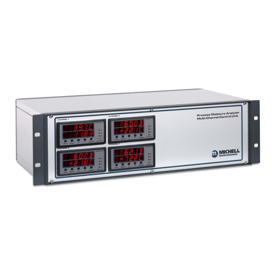
Zone 0, 1 or Zone 2 (Class I, Division 1, Groups A, B, C & D) hazardous area. The control unit and transmitters are connected via a standard 2-wire instrumentation cable protected by safety isolation interface units. Liquidew I.S. Control Unit Figure 1 Michell Instruments... -
Page 10: Performance Features
Liquidew I.S. User’s Manual INTRODUCTION Performance Features • State-of-the-art ceramic moisture sensor with chemically inert materials coupled with physical resilience provides long-term reliability in the most arduous applications. Robust construction is exceedingly durable in liquid. Not affected by pressure shocks. •... -
Page 11: Theory Of Operation
fl uid compositions where the user may wish to enter values from: • their own sources • laboratory analysis of process samples • estimated values from proportional calculation based on the values for each of the major components in the solute mix Michell Instruments... -
Page 12: System Components
Liquidew I.S. User’s Manual INTRODUCTION System Components The Liquidew I.S. Process Moisture Analyzer consists of: • the sensor assembly • the control unit Sensor Assembly Control Unit (Up to four channels can have any combination of Liquidew I.S. and Promet I.S.*) Temperature transmitter Sensor block Dew-point transmitter... -
Page 13: User Interface
Select selection. Select • key: The key is used to scroll up through pages in the top and sub- level menus and to increase values in sub-level menus. Michell Instruments... - Page 14 Liquidew I.S. User’s Manual INTRODUCTION • key: The key is used to scroll down through pages in the top and sub-level menus and to decrease values in sub-level menus. • Display key is used to change the display unit (see Section Display 3.2.2).
-
Page 15: Power Supply And Input/Output Signal
A contacts rated 5A / 240 V AC or 4A / 24 V DC, non-inductive load. The control actions and set points of these four alarms are user-programmable. A fault alarm with adjustable set points is also included. Michell Instruments... -
Page 16: Sampling System
Maximum pressure: 45 MPa (450 barg / 6526 psig) • Flow rate: 0.1 to 0.3 l/min (0.026 to 0.079 GPM) NOTE: Contact Michell Instruments if you wish to order a specifi c sampling system. Please refer to the Liquidew I.S. Premium Sampling System Instructions if a Michell sampling system has been ordered with the Liquidew I.S. -
Page 17: Installation
Remove the end packing pieces and set the control unit down at the site of installation. Save all the packing materials for the purpose of returning the instrument to the manufacturer for service. If ordered, the Liquidew I.S. Premium Sampling System will be shipped in a separate box. Michell Instruments... -
Page 18: Operating Requirements
Liquidew I.S. User’s Manual INSTALLATION Operating Requirements 2.2.1 Environmental Requirements The Liquidew I.S. sensor assembly is intrinsically safe and designed to be installed on-site, indoors or outdoors, directly at the point of measurement within a Hazardous Area. The sensor assembly is ATEX, IECEx, CSA and FM certifi ed. To operate correctly, the sensor assembly must be installed within a suitable sampling system (Michell Instruments can supply standard and custom designed sampling systems). -
Page 19: Figure 6 Rack Mounting Method
Connect the power supply cable and switch the switch to ON/OFF Re-fi t any covers to the rack as necessary. NOTE: Allow a minimum clearance depth of 100mm (4”) behind the instrument housing for cables and vents. Michell Instruments... -
Page 20: Mounting The Liquidew I.s. Sensor Assembly Into The Sampling System
Liquidew I.S. User’s Manual INSTALLATION 2.3.2 Mounting the Liquidew I.S. Sensor Assembly into the Sampling System HIGH PRESSURE! High pressure liquids are potentially hazardous. Energy stored in these liquids can be released suddenly and with extreme force. High pressure systems should be assembled and operated only by people who have been trained in proper safety practices. - Page 21 Michell recommends that a flow-rate of 0.1 to 0.3 l/min (0.026 to 0.079 GPM) (or equivalent at pressure) be set and that the dew-point transmitter is mounted as close as practicably possible to the point of measurement. Michell Instruments...
-
Page 22: Sampling System Installation
Connect the liquid inlet and outlet tubing to the fi ttings of the inlet/ outlet ports on the sampling system. If the sampling system has been ordered from Michell Instruments, the fi tting is a 6mm or 1/4” Swagelok ®... -
Page 23: Wiring
ALARMS ALARM 1 ALARM 3 OUTPUT 1 OUTPUT OUTPUT 2 COMMS RS 485 90-264 VAC POWER POWER SUPPLY SOCKET (BY OTHERS) 10-72 VDC POWER POWER SUPPLY CONNECTOR (BY OTHERS) SAFE AREA HAZARDOUS AREA Figure 8 Overall Wiring Arrangement Michell Instruments... -
Page 24: Control Unit Wiring
Liquidew I.S. User’s Manual INSTALLATION 2.4.2 Control Unit Wiring The electrical connections are located at the rear panel of the control unit. There are spaces for four individual channels. HAZARDOUS AREA INFORMATION: The only connections on the control unit which can take cables from hazardous area are the connectors labelled SENSOR INPUTS ALL OTHER CONNECTORS MUST NOT BE CONNECTED TO... -
Page 25: Figure 9 Control Unit Electrical Connections
ALARMS SP2 SP4 SP1 SP3 NO NC COM NO NO NC COM NO Alarm output User interface key lock OUTPUT mA1 0V mA2 LOCK OFF ON Analog output COMMS RS485 RS485 port Control Unit Electrical Connections Figure 9 Michell Instruments... -
Page 26: 2.4.2.1 Power Supply Input Connection
Liquidew I.S. User’s Manual INSTALLATION 2.4.2.1 Power Supply Input Connection 85 to 265 V AC The AC power supply connection is a push fi t socket labelled as shown POWER INPUT below. POWER INPUT Socket IEC connector POWER INPUT Socket Figure 10 The method of connection is as follows: Turn off the AC power. -
Page 27: Figure 11 Power Input Connector Block
Connect the free end of the power cable to a suitable DC power supply source (voltage range 10 to 72 V DC). The instrument may then be switched on, as required, by the power switch at the source. Michell Instruments... -
Page 28: 2.4.2.2 Sensor Signal Input Connection
Liquidew I.S. User’s Manual INSTALLATION 2.4.2.2 Sensor Signal Input Connection HAZARDOUS AREA INFORMATION Cables from transmitters mounted in hazardous areas can be connected directly to the connector block. SENSOR INPUTS There are built-in Galvanic I.S. barriers for all connections made to this connector block. Refer to ATEX/CSA/FM/IECEx certifi... -
Page 29: 2.4.2.3 Analog Output Connection
Insert the –4-20 mA lead into the terminal way on the terminal block and tighten the screw. Check that the wiring has been completed correctly. Push the terminal block fi rmly back into the socket. OUTPUT Michell Instruments... -
Page 30: 2.4.2.4 Alarm Output Connection
Liquidew I.S. User’s Manual INSTALLATION 2.4.2.4 Alarm Output Connection Four alarm output ports are provided and are connected to the instrument via a single 8-way push fi t connector block labelled as shown below. ALARMS ALARMS socket Terminal bock ALARM Connector Block Figure 14 Alarm 1 (connection labelled as SP1) and Alarm 2 (connection labelled as SP2) are Form... -
Page 31: 2.4.2.5 Rs485 Port Connection
The RS485 connection is a push-fi t socket labelled as shown in Figure 9. COMMS The method of connection is as follows: Pin Number Function Check the orientation of the RS485 connector and gently push it into the socket. Tighten the two screws on the connector. Michell Instruments... -
Page 32: Sensor Assembly Wiring
Liquidew I.S. User’s Manual INSTALLATION 2.4.3 Sensor Assembly Wiring NOTE: If the analyzer has been ordered with a sampling system, the Liquidew I.S. sensor assembly will be factory-wired to the junction box. In that case disregard the following instructions and go to Section 3. 2.4.3.1 Dew-point Transmitter Wiring HAZARDOUS AREA INFORMATION The dew-point transmitter (Easidew PRO I.S.) is certifi... -
Page 33: Figure 15 Crimped Wires
Crimped Wires Cut to 5mm Figure 15 Figure 16 Cable connection to the dew-point transmitter is made via the terminal block (4) (see Figure 17) . Remove the terminal housing lid (2) to access. Dew-Point Transmitter Housing Figure 17 Michell Instruments... -
Page 34: Figure 18 Dew-Point Transmitter Pin Assignment Drawing
Liquidew I.S. User’s Manual INSTALLATION Ensure that the outer diameter of the selected cable is matched to an EExe M20 cable gland (5). Unscrew the cable gland (5) and slide the cable through the cable gland (5) and into the terminal housing (1) through the cable entry (3). -
Page 35: 2.4.3.2 Temperature Transmitter Wiring
Ensure that the outer diameter of the selected cable is matched to an EExe M20 cable gland (5). Unscrew the cable gland (5) and slide the cable through the cable gland (5) and into the terminal housing (1) through the cable entry (3). Michell Instruments... -
Page 36: Figure 20 Temperature Transmitter Pin Assignment Drawing
Liquidew I.S. User’s Manual INSTALLATION Connect the signal cable leads to the terminals on the terminal block (4) in accordance with the following pin-assignment drawing. Pin designations are marked adjacent to each pin. SENSOR INPUTS Block Dew Point Temp Supply + 4-20 mA lead 4-20 mA - 4-20 mA lead... -
Page 37: Operation
The lock switch is located on the back panel of the control unit (see Figure 9) . It must be switched to position to activate the function keys. NOTE: Remember to lock the function keys after each operation. Michell Instruments... -
Page 38: Powering-Up The Analyzer
Liquidew I.S. User’s Manual OPERATION 3.2.2 Powering-up the Analyzer For the AC power supply version of the Liquidew I.S., turning on the power switch on the back panel of the control unit will power-up the control unit and the two transmitters. There is no power switch for the DC power supply version. -
Page 39: Sample Flow Start-Up
Follow the Liquidew I.S. Premium Sampling System Instructions to establish the sample fl ow of: 0.1 to 0.3 l/min (0.026 to 0.079 GPM) If the Liquidew I.S. Analyzer is to be fi tted to a non-Michell sampling system, the sample requirements listed in Section 1.5 must be fulfi lled. Michell Instruments... -
Page 40: Menu Structure
Liquidew I.S. User’s Manual OPERATION Menu Structure The Liquidew I.S. main menu has a two level menu structure. There are three sub- menus - . The LIQUID SETUP, OUTPUT SETUP FAULT SETUP ALARM SETTINGS are not in the main menu and are accessed separately. These are described in detail in following sections. -
Page 41: Figure 22 Menu Maps
Select SPC_1 000-high 100-low Select Select Select Source SPC_2 Select 000-high 100-low Select Select Select Source SPC_3 Select 000-high 100-low Select Select Select Source Select SPC_4 000-high 100-low Select Select - Main Reading Page Figure 22 Menu Maps Michell Instruments... -
Page 42: Main Reading Page
Liquidew I.S. User’s Manual OPERATION Main Reading Page The Main Reading Page is the default screen shown after turning the instrument on. It will display the units of measurement selected by the user (see Section 3.2.2). Liquid Set-Up The saturation concentration values of the sample liquid need to be specifi... -
Page 43: User-Defi Ned Liquid
Page, and calculations will then based on the USER 1 solubility profi le. For the second user-defi ned liquid USER 2, the solubility profi le can be entered in USER 2, following the above procedure: U S E R U S E R Michell Instruments... -
Page 44: Liquid Mixing
Liquidew I.S. User’s Manual OPERATION 3.5.3 Liquid Mixing The user can defi ne the solubility profi le for a liquid by mixing any two liquids from the liquid list, including USER 1 and USER 2, with an editable ratio. In the liquid list in the sub menu, use the ... - Page 45 NOTE: Follow Section 3.5.2 to defi ne the USER 1 / USER 2 solubility profi le fi rst if you want to select them for mixing. NOTE: The next time liquid mixing is entered it will go directly to the currently selected liquid. Michell Instruments...
-
Page 46: Analog Output 1 (Moisture Content Or Dew Point - User-Selectable)
Liquidew I.S. User’s Manual OPERATION Analog Output 1 (Moisture Content or Dew Point - User-Selectable) The source and scale of the 4-20 mA output can be confi gured in the OUTPUT SETUP menu. From the Main Reading Page, press to enter the main menu. Use the key to Menu scroll to the option. -
Page 47: Output Range Zero Value Settings
Main Reading Page (refer to Section 3.2.2). The value will be automatically converted based on the new units selected. Analog Output 2 (Sample Temperature - Only) Analog Output 2 has a fi xed temperature signal of 0 to +60°C (+32 to +140°F) and cannot be confi gured. Michell Instruments... -
Page 48: System Fault Alarm Set-Up
Liquidew I.S. User’s Manual OPERATION System Fault Alarm Set-Up There are four conditions for the system fault alarm which can be confi gured in the sub menu. NOTE: If any of the fault alarm conditions occur during FAULT SETUP system operation will rise to 21mA for both high and low errors. -
Page 49: Minimum Temperature Value For The Fault Alarm
Select Reading Page. NOTE: The units will be either C(ºC) or F(ºF) depending on the unit selection in the Main Reading Page (refer to Section 3.2.2). The value will be converted automatically based on the new units selected. Michell Instruments... -
Page 50: Alarm Setting
Liquidew I.S. User’s Manual OPERATION Alarm Setting There are 4 built-in alarm relays which can be confi gured independently. From the Main Reading Page, press and hold the key then press the key to enter the ‘ALARM Select SETTING’ page. 0. -
Page 51: Alarm Type Selection
The display will then change to the Alarm Select Control Setting for Alarm Relay 2. Repeat steps (a) and (b) to adjust the type (high/low) for Alarm Relay 2, Alarm Relay 3 and Alarm Relay 4 accordingly. Michell Instruments... -
Page 52: Alarm Source Selection
Liquidew I.S. User’s Manual OPERATION 3.9.3 Alarm Source Selection The alarm source can be also selected in the Alarm Control Setting page. From the Main Reading Page, press and hold the key then press the key to Select enter the ‘ALARM SETTING’ page. Press the key until SPC_1 is shown. The user can select (moisture), (dew point °C),... -
Page 53: Display Brightness Adjustment
‘BRIGHTNESS ADJUSTMENT’ page. B R I Use the and keys to adjust the display brightness. Press the key to confi rm the adjustment. Press the Select Select again to return to the Main Reading Page. Michell Instruments... - Page 54 Liquidew I.S. User’s Manual APPENDIX A Appendix A Technical Specifi cations 97092 Issue 5.1, October 2018...
-
Page 55: Appendix A Technical Specifi Cations
Two Form A contacts rated 5A / 240 V AC or 4A / 24 V DC Non-inductive load I.S. Barriers Galvanic isolation type, integrated to Control Unit 85 to 265 V AC 47/63Hz or 10 to 72 V DC Power Supply 10 W max power consumption Michell Instruments... - Page 56 Liquidew I.S. User’s Manual APPENDIX A 19” sub rack unit Enclosure Dimensions: 132 x 483 x 375mm (5 x 19 x 14.75”) (h x w x d) (100mm (4”) minimum rear clearance depth for cables and vents) Operating Environment Indoor, safe area, 0 to +50°C (+32 to +122°F), < 90% RH Premium Sampling Systems 304 stainless steel (EN1.4301) enclosure Option for complete enclosure in 316 stainless steel (EN1.4401)
-
Page 57: Figure 23 Dimensional Drawings
Liquidew I.S. User’s Manual APPENDIX A Dimensional Drawings 375mm + 100mm for cable clearance (14.75” + 3.9”) CHANNEL 1 CHANNEL 3 CHANNEL 2 CHANNEL 4 483mm (19”) Figure 23 Dimensional Drawings Michell Instruments... - Page 58 Liquidew I.S. User’s Manual APPENDIX B Appendix B Serial Communications 97092 Issue 5.1, October 2018...
-
Page 59: Appendix B Serial Communications
It will be necessary to match up the A/B (Differential data pair) and GND (0 V) pins with the wiring of your own third party adaptor. E.g. For the K3-ADE RS232->RS485 adaptor use the following wiring: Pin Name Liquidew DB9 Pin K3-ADE DB9 Pin This wiring is the generally accepted standard for most 2-wire RS485 equipment. Michell Instruments... - Page 60 Liquidew I.S. User’s Manual APPENDIX B Setting the Address of the Monitor This procedure needs to be done for either ASCII or MODBUS RTU protocols. a. Press the and keys simultaneously to display the BRI (brightness) Select menu. b. Press the key again to display the CAL (calibration) menu.
- Page 61 1 to 65535 to 9999999 • Reading the dew-point value from a meter that has an address of 2: Send: s2r253$ • Reading the LBMMSCF from a meter that has an address of 5: Send: s5r244$ Michell Instruments...
- Page 62 Liquidew I.S. User’s Manual APPENDIX B MODBUS RTU Once the protocol has been set the monitor will communicate in accordance with the standard Modbus RTU protocol. command should be used to read the registers listed in the register Read Holding Registers map.
- Page 63 Liquidew I.S. User’s Manual APPENDIX C Appendix C Modbus RTU Comms Michell Instruments...
-
Page 64: Appendix C Modbus Rtu Comms
ON after making any required changes to the confi guration codes. Adjusting confi guration codes without the express written instruction of Michell Instruments may result in damage to the monitor that is NOT covered under warranty. 97092 Issue 5.1, October 2018... - Page 65 Liquidew I.S. User’s Manual APPENDIX C Michell Instruments...
- Page 66 Liquidew I.S. User’s Manual APPENDIX D Appendix D Hazardous Area Certifi cation 97092 Issue 5.1, October 2018...
-
Page 67: Appendix D Hazardous Area Certifi Cation
IS, Class I, Division 1, Groups A, B, C & D, T4 Global Certifi cates/Approvals ATEX Baseefa 06ATEX0330X ATEX System Baseefa 07Y0027 IECEx IECEx BAS 06.0090X 2013218 3030238 TC TR Ex RU C-GB. ГБ05.B.00229 These certifi cates can be viewed or downloaded from our website at: http://www.michell.com Michell Instruments... -
Page 68: Terminal Parameters
Maintenance and servicing of the product must only be carried out by suitably trained personnel or returned to an approved Michell Instruments’ Service Ce 97092 Issue 5.1, October 2018... - Page 69 Liquidew I.S. User’s Manual APPENDIX E Appendix E System Drawings Michell Instruments...
-
Page 70: Appendix E System Drawings
Liquidew I.S. User’s Manual APPENDIX E Appendix E System Drawings Baseefa Approved System Drawing 97092 Issue 5.1, October 2018... -
Page 71: Fm Approved System Drawing
Liquidew I.S. User’s Manual APPENDIX E FM Approved System Drawing Michell Instruments... -
Page 72: Csa Approved System Drawing
Liquidew I.S. User’s Manual APPENDIX E CSA Approved System Drawing 97092 Issue 5.1, October 2018... - Page 73 Liquidew I.S. User’s Manual APPENDIX F Appendix F Quality, Recycling & Warranty Information Michell Instruments...
-
Page 74: Appendix F Quality, Recycling & Warranty Information
Liquidew I.S. User’s Manual Appendix F Quality, Recycling & Warranty Information Michell Instruments is dedicated to complying to all relevant legislation and directives. Full information can be found on our website at: www.michell.com/compliance This page contains information on the following directives: •... -
Page 75: Warranty
All warranty services are provided on a return to base basis. Any transportation costs for the return of a warranty claim shall reside with the Customer. Return Policy If a Michell Instruments’ product malfunctions within the warranty period, the following procedure must be completed: Notify a Michell Instruments’ distributor, giving full details of the problem, the model variant and the serial number of the product. -
Page 76: Calibration Facilities
APPENDIX F Liquidew I.S. User’s Manual Calibration Facilities Michell Instruments’ calibration facilities are among the most sophisticated in the world and have been recognized for their excellence. Traceability to the National Physical Laboratory (NPL) UK is achieved through our UKAS Accreditation (Number 0179). - Page 77 Liquidew I.S. User’s Manual APPENDIX G Appendix G Return Document & Decontamination Declaration Michell Instruments...
-
Page 78: Appendix G Return Document & Decontamination Declaration
Has the equipment been cleaned and decontaminated? NOT NECESSARY Michell Instruments will not accept instruments that have been exposed to toxins, radio-activity or bio-hazardous Work will not be carried out on any unit that does not have a completed decontamination declaration. - Page 79 Liquidew I.S. User’s Manual NOTES: Michell Instruments...
- Page 82 http://www.michell.com...
Need help?
Do you have a question about the Liquidew I.S. and is the answer not in the manual?
Questions and answers