
Related Manuals for Michell Instruments XTP601


Summary of Contents for Michell Instruments XTP601
- Page 1 XTP601 Process Oxygen Analyzer User’s Manual Back. Gas: N2 20.91 % 02 Cell T Not Stable 97313 Issue 5.1 July 2018...
- Page 2 Please fi ll out the form(s) below for each instrument that has been purchased. Use this information when contacting Michell Instruments for service purposes. Analyzer Code Serial Number Invoice Date Location of Instrument Tag No Analyzer Code Serial Number Invoice Date...
- Page 3 © 2018 Michell Instruments This document is the property of Michell Instruments Ltd. and may not be copied or otherwise reproduced, communicated in any way to third parties, nor stored in any Data Processing System without the express written authorization of Michell Instruments Ltd.
-
Page 4: Table Of Contents
XTP601 User’s Manual Contents Safety ..........................vii Electrical Safety ......................vii Pressure Safety ......................vii Temperature Safety ..................... vii Toxic Materials ......................vii Repair and Maintenance ....................vii Calibration ........................vii Safety Conformity ....................... vii Equipment Ratings ...................... vii Abbreviations ........................viii Warnings .......................... - Page 5 1 Point Calibration Page ................23 Figure 27 2 Point Calibration Page ................24 Figure 28 Field Calibration Reset Page ..............25 Figure 29 XTP601 Cutaway Showing Major Components ..........28 Figure 30 XTP601 Lid Removal .................29 Figure 31 XTP601 Cable Entries ................30 Figure 32 Terminal Block Locations ................31...
- Page 6 XTP601 User’s Manual Appendices Appendix A Technical Specifications ................36 Dimensions Ex version ..............38 Appendix B Modbus Register Map ................40 Appendix C Hazardous Area Certification ..............47 Product Standards ..............47 Product Certifi cation ..............47 Global Certifi cates/Approvals ............47 Special Conditions...............
-
Page 7: Safety
Repair and Maintenance The instrument must be maintained either by the manufacturer or an accredited service agent. For Michell Instruments’ worldwide offices contact information go to www.michell.com. Calibration The recommended calibration interval for the analyzer is 3 months. Depending on the application in which the instrument is used, the calibration interval may be reduced. -
Page 8: Abbreviations
XTP601 User’s Manual Abbreviations The following abbreviations are used in this manual: Ampere alternating current bara pressure in bar (absolute) barg pressure in bar (gauge) °C degrees Celsius °F degrees Fahrenheit direct current kilogram Kilopascal pound maximum milliampere ml/min milliliters per minute... -
Page 9: Introduction
INTRODUCTION XTP601 User’s Manual INTRODUCTION This manual will show how to measure oxygen easily using the XTP601 Oxygen Analyzer. The following sections contain information about: • Analyzer components • Operating instructions • Calibration and maintenance of the Analyzer • Installation Please read this manual carefully and pay special attention to the safety warnings and notifications. -
Page 10: Features
• The XTP601 is certified to ATEX, IECEX, cCSAus, INMETRO & TC TR Ex for use in hazardous areas. •... -
Page 11: Applications
XTP601 User’s Manual Applications The XTP601 has a robust sensor with high sensitivity and stability. It can be factory- calibrated in varying backgrounds to match the customer’s process gas. The analyzer has a built-in local user interface with a display. The capacitive buttons work through the glass face, without needing to remove the lid. -
Page 12: Operation
XTP601 User’s Manual OPERATION OPERATION The XTC601 is not certifi ed for use with ambient oxygen levels that are enriched (i.e. over 21% O2) This analyzer has been manufactured within our quality procedures and is configured according to the purchase order. When it is installed and used as per the manufacturer’s guidelines, it will operate within the stated specification. -
Page 13: Powering Up The Analyzer
There is no power switch on the XTP601 Oxygen Analyzer. It is turned on automatically once a 24 V DC power source is applied. After the analyzer is powered up, the display will be illuminated. -
Page 14: User Interface
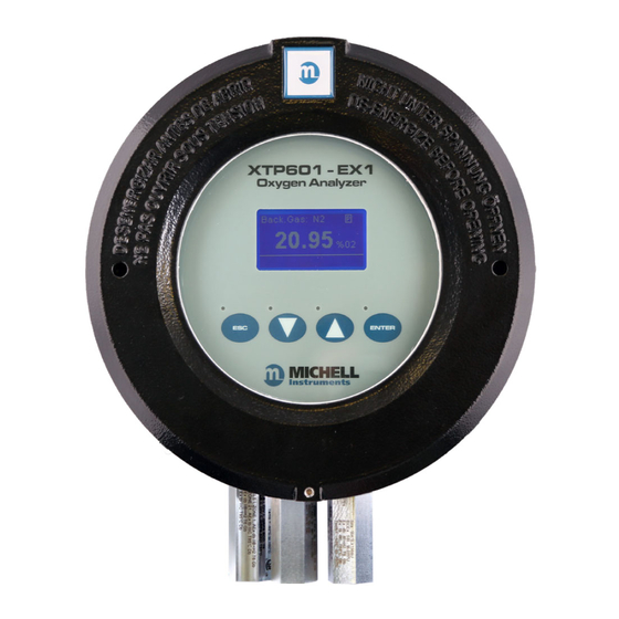
XTP601 User’s Manual OPERATION User Interface 2.3.1 Interface Controls XTP601-EX1 Oxygen Analyzer Backlit LCD Blue LEDs ENTER Up/Down ENTER Arrow Button Button Buttons User Interface Figure 4 The diagram above illustrates the user interface, which consists of a backlit Liquid Crystal Display and 4 touch-sensitive pads that facilitate user interaction through the glass of the enclosure. -
Page 15: Esc' Button
XTP601 User’s Manual OPERATION 2.3.2 ‘ESC’ Button ESC Button Figure 6 button is used to exit the current menu and to return to the previous menu. From the Main Page, pressing will access the Info Page. 2.3.3 ‘Up/Down Arrow’ Buttons... -
Page 16: Menu Structure
OPERATION Menu Structure The EX1 and GP1 versions of the XTP601 have front pages that do not require a passcode but allow the user to scroll through and view oxygen concentration, recent trend, internal parameters, minimum & maximum oxygen concentration and alarm history. -
Page 17: Menu Map
Figure 9 Front Pages (No passcode Required) The EX1 and GP1 versions of the XTP601 have 5 front pages that the user can display without t he need for a passcode. NOTE: These are for display of information only and there is no way of adjusting any settings on these pages. -
Page 18: Main Page
XTP601 User’s Manual OPERATION 2.5.1 Main Page Back. Gas: N2 20.91 % 02 Cell T Not Stable Main Page Figure 10 Parameter Description Displays the background gas that the unit was calibrated in Background Gas Real oxygen reading in % % O2 Display resolution = 0.01... -
Page 19: Chart Page
XTP601 User’s Manual OPERATION 2.5.2 Chart Page Figure 11 Chart Page NOTE: This data is not available via the Modbus • This indicative chart is continuously running at the set chart interval (2 to 60 seconds). • Chart duration in seconds = (chart interval * 60). -
Page 20: Secondary Parameters Page
XTP601 User’s Manual OPERATION 2.5.3 Secondary Parameters Page CELL T, °C 50.0 PCB TEMP, C COMP I/P EXT I/P Secondary Parameters Page Figure 12 Parameter Description Sensor cell temperature display in set unit (°C, °F or Kelvin) CELL T Display Resolution = 0.1... -
Page 21: Alarms Log Pages
XTP601 User’s Manual OPERATION 2.5.5 Alarms Log Pages ALARM DATE TIME 02/01 12:50:40 02/01 11:10:32 02/01 11:00:29 02/01 10:20:00 Figure 14 Alarms Log Page A maximum of 40 High/Low alarms, along with date and time of occurrence, are recorded in a ring buffer in NV memory. The most recent alarm will overwrite the oldest alarm when more than 40 alarms are recorded. -
Page 22: User Set-Up Variables (Passcode Required)
XTP601 User’s Manual OPERATION User Set-Up Variables (Passcode Required) In order to change any settings on the User Menu pages, the user must enter a passcode. There is also a separate passcode for service engineers to allow factory setting changes. -
Page 23: Settings Page
XTP601 User’s Manual OPERATION 2.7.1 Settings Page FIELD CAL ON/OFF PRESS COMP ON/OFF EXT COMP ON/OFF ON/OFF ON/OFF LIMIT 0-100% 1-127 MODBUS ID Settings Page Figure 17 The analyzer is microprocessor-based and, as such, has settings and features accessible to the user. -
Page 24: Human Machine Interface (Hmi) Page
XTP601 User’s Manual OPERATION 2.7.2 Human Machine Interface (HMI) Page CONTRAST O-100% BRIGHTNESS O-100% TEMPR UNIT C/F/K EXT PRESS UNIT psia, bara, kpa 2-60s CHART INTVAL DD/MM/YY DATE Figure 18 HMI Page It is possible to change parameters within the HMI, as shown below:... -
Page 25: Reset Page
XTP601 User’s Manual OPERATION 2.7.4 Reset Page O2 MIN/MAX RESET? ALARM LOGS DELETE? DELETE? FIELD CAL Figure 20 Reset Page 02 Min/Max and Alarm Logs can be cleared from this menu. See Sections 2.5.4 and 2.5.5 respectively for more information. -
Page 26: External Compensation Page
XTP601 User’s Manual OPERATION 2.7.6 External Compensation Page 0.50-2.00 COMP 20% COMP 40% 0.50-2.00 COMP 60% 0.50-2.00 COMP 80% 0.50-2.00 COMP 100% 0.50-2.00 External Compensation Page Figure 22 A 4-20 mA sensor may be used to compensate the % O reading for the effects of process variables such as line pressure, flow, etc. -
Page 27: External Sensor Page
This page sets up the type and range of the 4-20 mA external sensor signal that may be connected to the XTP601 for viewing in the Main Page. The range is adjustable between the MIN and MAX values but is not adjustable for... -
Page 28: Field Cal Page
XTP601 User’s Manual OPERATION 2.7.8 Field Cal Page CAL TYPE 1/2 POINT REF GAS 1 0.00-100.00 ACTUAL 1 0.00-100.00 REF GAS 2 0.00-100.00 0.00-100.00 ACTUAL 2 Adjusted ~ **.** Field Cal Page Figure 24 Setting Description/Operation 1 POINT or 2 POINT... -
Page 29: Light Guide Option
XTP601 User’s Manual OPERATION 2.7.9 Light Guide Option The light guide is an optional accessory fitted, ideally, to the left hand cable entry and has a red and green LED to display the status. • Green On - indicates instrument power is on. -
Page 30: Calibration
Test Result Sheet or a Michell Instruments' representative Field Calibration: Like all process analyzers, the XTP601 will require periodic calibration. The frequency entirely depends on the location, application and accuracy requirements of the user. The typical calibration period is expected to be between 1 and 3 months with a Zero gas and a Span calibration on a monthly basis. -
Page 31: Point Calibration
XTP601 User’s Manual CALIBRATION 1 Point Calibration This is a single point offset overlaid on top of the factory calibration. It is designed to correct minor drift and minor changes during transit. This calibration makes the unit very accurate at the calibration point and improves accuracy throughout the range. -
Page 32: Point Calibration
XTP601 User’s Manual CALIBRATION 2 Point Calibration This is a 2 point adjustment that is overlaid on top of the factory calibration. It is designed to correct minor drift and minor changes during transit. This calibration makes the unit more accurate throughout the range than the single point calibration. -
Page 33: Field Calibration Reset
XTP601 User’s Manual CALIBRATION The Adjusted reading will now be the same as that displayed on the Main Page and be equal to the upper calibration gas. The calibration process is complete. Return to sampling the process gas. NOTE: The analyzers leave the factory with the field calibration function turned off. -
Page 34: Installation
'hot works' permit. Special care must be taken when the analyzer is energized. The XTP601-EX versions must only be installed by suitably qualifi ed personnel and in accordance with the instructions provided and the terms of the applicable product certifi... -
Page 35: Unpacking
INSTALLATION Unpacking If sold separately (not part of a sampling system), the XTP601 will be supplied in a custom box which should be retained for future use (such as service return). The box contains a small carton containing 2 lid keys and 1 hex key (for the grub screw). Any cable glands supplied will also be in the smaller carton. -
Page 36: System Components
INSTALLATION XTP601 User’s Manual System Components The XTP601 Oxygen Analyzer benefits from a modular construction, with the major parts of the analyzer shown below: Figure 28 XTP601 Cutaway Showing Major Components Lid with display and touch screen Instrument case Measuring cell... -
Page 37: Set-Up
Set-Up • The XTP601 is designed to be panel or wall mounted. There are 2 bolt holes and 2 lugs (1 per corner) see Figure 11. Dimensional drawings can be found in Appendix B. Mount the analyzer before attempting to remove the lid. -
Page 38: Mechanical Installation
PTFE tape used must be unsintered. This is to prevent an explosion due to conventional PTFE tape acting as a potential fuel source. Unsintered PFTE tape is available as an accessory from Michell Instruments (PTFE- TAPE-02). 4.4.2 Sample Gas Requirements Samples must have a dew point at least 10°C less than the cell temperature (so as not... -
Page 39: Calibration Gases
4.5.1 Power Supply and Input/Output Signal The XTP601 requires 24 V DC power input at a maximum start-up current of 1.5 A. All versions will use a braid screened multi-core cable. Ideally, one cable for signals (PL4, PL5) and another cable for power (PL9) / relay contacts (PL1). Braid of cables must be well terminated at the cable glands. -
Page 40: Signal Output
INSTALLATION XTP601 User’s Manual 4.5.3 Signal Output There are two 4-20mA linear signal output channels. Both are for oxygen concentration. One is fixed on the calibrated range of the unit and the second can be configured in the menu. NOTE: When the instrument is warming up (cell temperature not stabilized) these outputs are factory set to 3.2 mA to indicate that the... -
Page 41: Alarm Relay Contacts (Pl1- Black)
PIN 2 PIN 1 Exc.V Exc.V The XTP601 features 2 input channels for 4-20 mA signal from external instruments such as pressure transmitters or other devices to compensate for pressure or background gas influence. The input configured as (External Sensor) can be viewed on the Secondary... -
Page 42: Light Guide
Hazardous Area version of the analyzer this must be specified at time of purchase order. If fi tted in a Hazardous Area (EX) version of the XTP601 the light guide not be dismantled by the user. Dismantling the Light Guide will invalidate the the certifi cation. -
Page 43: Appendix A Technical Specifications
APPENDIX A XTP601 User’s Manual Appendix A Technical Specifi cations Michell Instruments... - Page 44 XTP601 User’s Manual APPENDIX A Appendix A Technical Specifi cations Performance Measurement Technology Thermo-paramagnetic oxygen sensor Process and non-condensing sample with particles <3μm Measurement Range Select from 0-0.5% up to 0-50% and 20-100% up to 90-100% Display Resolution 0.01% (0.1% for suppressed zero ranges)
- Page 45 Viton: Ta = -15 to +55°C O-Ring type Ekraz: Ta = -10 to +55°C The XTP601 process oxygen analyzer meets or exceeds all relevant clauses in BS EN 50104 : 2010 “Electrical apparatus for the detection and measurement of oxygen”. Michell Instruments...
-
Page 46: Figure 33 Xtp601 Dimensional Drawings
XTP601 User’s Manual APPENDIX A Dimensions Ex version 234 mm (9.21'') 9 mm (0.35'') 11.5 mm TY P (0.45'') 172 mm (6.77'') 172 mm (6.77'') 15.5 mm (0.61'') 12.0 mm (0.47'') 171 mm (6.73'') 195 mm (7.68'') 30 mm (1.18'') 1/8"... - Page 47 APPENDIX B XTP601 User’s Manual Appendix B Modbus Register Map Michell Instruments...
-
Page 48: Appendix B Modbus Register Map
APPENDIX B XTP601 User’s Manual Appendix B Modbus Register Map Compatible with XTP601 Firmware Version: V1:03 Addr Function Access Ranges/Resolution Type Modbus Instrument Address (ID) 1-127 Settings Register 0-65535 Display Contrast / Brightness 0-100% / 0-100%, 10% steps Units Register... - Page 49 APPENDIX B XTP601 User’s Manual Addr Function Access Ranges/Resolution Type Cal 02 Ref3 0.00-100.00 Cal 02 Ref4 0.00-100.00 Cal 02 Ref5 0.00-100.00 Cal 02 ADC1 0-8191 Cal 02 ADC2 0-8191 Cal 02 ADC3 0-8191 Cal 02 ADC4 0-8191 Cal 02 ADC5...
- Page 50 APPENDIX B XTP601 User’s Manual Addr Function Access Ranges/Resolution Type Firmware Version 0.00-200.00 Live ADC 02 0-8191 Live ADC mA INPUT1 0-8191 Live ADC mA INPUT2 0-8191 Live ADC CellTempr 0-8191 Live ADC Pressure 0-8191 Live ADC PCB Tempr 0-8191 %O2 without field cal correction -199.00-199.99%...
- Page 51 APPENDIX B XTP601 User’s Manual Register Type C: Display Parameters Display Brightness Display Contrast 0-100 in 10% steps 0-100 in 10% steps Register Type D: Units Bits Meaning (binary) 0, 1 0003 00=degC, 01=degF, 10=K 2, 3 000C Ext press unit, 00 = psia, 01=bara, 10=kPa...
- Page 52 APPENDIX B XTP601 User’s Manual Register Type I - Status/Error Meaning Namur LED Displays O2HSR or O2 depending on setting 0001 (system) %O2 out of range (beyond calibration range, 0002 e.g. 0-25%) 0004 AL1 ON YELLOW 1 ON 0008 AL2 ON...
- Page 53 APPENDIX B XTP601 User’s Manual Register Type J eg Month eg Day For reading each 8 bits represents a RTC value. For setting only the lower 8 bits are used for each RTC value. Register Type K: -32767 to +32767...
- Page 54 APPENDIX C XTP601 User’s Manual Appendix C Hazardous Area Certifi cation 97313 Issue 5, May 2018...
-
Page 55: Appendix C Hazardous Area Certification
Appendix C Hazardous Area Certifi cation The XTP601-EX Oxygen Analyzer is certified compliant to the ATEX Directive (2014/34/ EU) and IECEx for use within Zone 1 & 2 Hazardous Areas and has been assessed so by SIRA Certification (Notified Body 0518). -
Page 56: Maintenance And Installation
XTP601 User’s Manual Maintenance and Installation The XTP601-EX must only be installed by suitably qualified personnel and in accordance with the instructions provided and the terms of the applicable product certificates. Maintenance and servicing of the product must only be carried out by suitably trained personnel or returned to an approved Michell Instruments’... - Page 57 XTP601 User’s Manual APPENDIX D Appendix D Quality, Recycling, Compliance & Warranty Information Michell Instruments...
-
Page 58: Appendix D Quality, Recycling, Compliance & Warranty Information
XTP601 User’s Manual Appendix D Quality, Recycling, Compliance & Warranty Information Michell Instruments is dedicated to complying to all relevant legislation and directives. Full information can be found on our website at: www.michell.com/compliance This page contains information on the following directives: •... - Page 59 XTP601 User’s Manual APPENDIX E Appendix E Analyzer Return Document & Decontamination Declaration Michell Instruments...
-
Page 60: Appendix E Analyzer Return Document & Decontamination Declaration
Has the equipment been cleaned and decontaminated? NOT NECESSARY Michell Instruments will not accept instruments that have been exposed to toxins, radio-activity or bio-hazardous Work will not be carried out on any unit that does not have a completed decontamination declaration. - Page 61 XTP601 User’s Manual NOTES Michell Instruments...
- Page 64 http://www.michell.com...
Need help?
Do you have a question about the XTP601 and is the answer not in the manual?
Questions and answers