
Related Manuals for Michell Instruments SF82


Summary of Contents for Michell Instruments SF82
- Page 1 SF82 Online Dew-Point Hygrometer User’s Manual 99993 Issue 1 May 2020 nbn Austria GmbH...
- Page 2 Please fill out the form(s) below for each instrument that has been purchased. Use this information when contacting Michell Instruments for service purposes. Instrument Code Serial Number Invoice Date Location of Instrument Tag No Instrument Code Serial Number Invoice Date...
- Page 3 © 2020 Michell Instruments This document is the property of Michell Instruments Ltd and may not be copied or otherwise reproduced, communicated in any way to third parties, nor stored in any Data Processing System without the express written authorization of Michell Instruments Ltd.
-
Page 4: Table Of Contents
2.3.7.3 RS485 Modbus RTU Communications Port ..........13 2.3.8 Mounting the Monitor .................. 14 SF82 Transmitter ....................15 2.4.1 SF82 DIN 43650 Connector Version .............. 15 2.4.1.1 Electrical Connections ................16 2.4.1.2 Cable Connection to Transmitter ............. 16 2.4.1.3 Sensor Cable Self-Assembly ..............17 2.4.2... - Page 5 SF82 Online User’s Manual OPERATION ....................26 General Operational Information ............... 26 Preparation For Operation ................. 27 3.2.1 First-Time Operation ..................27 Monitor Setup ....................28 3.3.1 Change alarm type (high/low) ..............28 3.3.2 Change alarm set-points ................30 3.3.3 Analog output: change from 4–20mA to 0–20mA .......... 31 3.3.4...
- Page 6 Figure 17 Cable Assembly ..................17 Figure 18 Sensor Connector Installation ..............18 Figure 19 Maximum Load of SF82 – Including Cable Resistance ........19 Figure 20 Transmitter Mounting – Sensor Block ............21 Figure 21 Transmitter Mounting – Pipe or Duct ............22 Figure 22 Transmitter Mounting with Adapter ............23...
-
Page 7: Safety
The instrument should be returned to the manufacturer, Michell Instruments Ltd., or one of their accredited service agents for re-calibration. Safety Conformity This product meets the essential protection requirements of the relevant EU and US directives. -
Page 8: Abbreviations
SF82 Online User’s Manual Abbreviations The following abbreviations are used in this manual: alternating current pressure unit (atmosphere) barg pressure unit (=100 kP or 0.987 atm) gauge bara bar absolute °C degrees Celsius °F degrees Fahrenheit direct current foot (feet) -
Page 9: Introduction
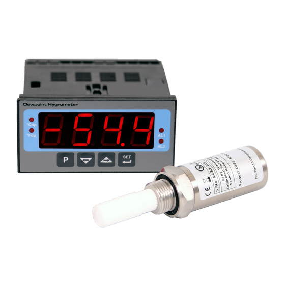
INTRODUCTION INTRODUCTION The SF82 Online Fast Response dew point hygrometer has been developed as a fast- response, quick-to-install hygrometer system for the complete dew-point measurement range of -60 up to +60°C (-76 up to +140°F) dew point, which covers many moisture measurement applications. -
Page 10: Features
SF82 Online User’s Manual INTRODUCTION Features The SF82 Online Hygrometer is simple to use and install, and can be configured to meet specific needs. • 5/8” - 18 UNF, 3/4” - 16 UNF, G1/2” BSP process connections • Dew point •... -
Page 11: Installation
SF82 Online User’s Manual INSTALLATION INSTALLATION It is essential that the connection of electrical and gas supplies to this instrument be undertaken by competent personnel. Unpacking the Instrument The Easidew instruments and accessories are packed into a box and the method of... -
Page 12: Unpacking The Sf82 Transmitter
SF82 Online User’s Manual INSTALLATION 2.1.1 Unpacking the SF82 Transmitter NOTE: For environmental and operating conditions refer to Appendix A. Unpack the dew-point transmitter box as follows : Transmitter Unpacking Method Figure 3 Unscrew the cap (1) from the packing tube (6). Remove the foam block (2). -
Page 13: Accessories Pack
Remove the screwdriver (1), the two leads (2) and (3) and the sample block (4) from the bag. SF82 Online Components On delivery please check that all the following standard components are present in the packing box. Report any shortages to Michell Instruments, immediately. SF82 Online Components Figure 6 Monitor clamps (2 off) -
Page 14: Monitor
SF82 Online User’s Manual INSTALLATION Monitor The controls and indicators associated with the SF82 Online are located on the front panel of the monitor. Connections to the SF82 dew-point transmitter, the digital communications port and the external power supply are all made to the rear panel of the monitor. -
Page 15: Monitor Controls And Indicators
SF82 Online User’s Manual INSTALLATION 2.3.2 Monitor Controls and Indicators Item Description °F units indicator Indicates that the displayed dew-point reading is in degrees Fahrenheit. °C units indicator Indicates that the displayed dew-point reading is in degrees Celsius. Main reading display Displays the value measured by the connected transmitter, or flashes one of the status conditions shown in Section 2.3.1. -
Page 16: Electrical Connections
SF82 Online User’s Manual INSTALLATION 2.3.3 Electrical Connections Electrical connections to the SF82 Online system are as follows: Required: • AC power supply, 100 to 240 V AC (-15%, +10%), 50/60 Hz, 6 VA. The low voltage (24 V DC) option is not available at present. -
Page 17: Figure 8 Monitor Rear Panel Connections
SF82 Online User’s Manual INSTALLATION Monitor Rear Panel Connections Figure 8 Terminal Wire Colour Signal Supply Information Blue 0 V (GND) Transmitter Cable Screen Green 4–20 mA loop return Transmitter loop supply +24 V DC w.r.t. terminal 1 (+ve) User defined... -
Page 18: Ac Power Supply Input
SF82 Online User’s Manual INSTALLATION 2.3.4 AC Power Supply Input It is essential that the connection of electrical supplies to this instrument be undertaken by competent personnel. Connect the AC power supply to the monitor as shown in Figure 9 . Refer also to Table 2 which gives a summary of all the connections to the rear panel of the monitor. -
Page 19: Dc Power Supply Input (Not Available At Present)
SF82 Online User’s Manual INSTALLATION 2.3.5 DC Power Supply Input (not available at present) Connect the DC power supply to the monitor as shown in Figure 10 . Refer also to Table 2 which gives a summary of all the connections to the rear panel of the monitor. -
Page 20: Transmitter Connection
SF82 Online User’s Manual INSTALLATION 2.3.6 Transmitter Connection Connect the transmitter cable to the monitor as shown below: 1 0 1 2 2 2 0 2 1 1 9 2 7 1 8 1 6 1 1 4 1 Monitor... -
Page 21: Signal Output Connections
2.3.7 Signal Output Connections The SF82 Online system has four possible signal outputs: Alarm 1 (ALr1), Alarm 2 (ALr2), the re-transmitted input signal (4–20 mA or 0–20 mA current loop signal depending upon instrument configuration) and the digital communications interface. -
Page 22: Mounting The Monitor
SF82 Online User’s Manual INSTALLATION 2.3.8 Mounting the Monitor The monitor is designed for panel mounting and requires a panel cut-out of 46 x 92mm (1.8 x 3.6”). The recommended panel thickness is 2 to 5mm (0.08 to 0.2”). To mount the unit, proceed as follows (refer to Figure 13): Pass the monitor (1) through the front of the panel (2). -
Page 23: Sf82 Transmitter
NOTE: The transmitter’s sensing element is shown for illustration purposes only. Please keep the guard fitted at all times, if possible. Figure 14 SF82 Transmitter 2.4.1 SF82 DIN 43650 Connector Version The following sections apply only to the DIN 43650 connector version of the SF82 Online. Michell Instruments... -
Page 24: 2.4.1.1 Electrical Connections
NOTE: The sensor cable is supplied as standard. Replacement pre-wired cables can be obtained by contacting your local Michell Instruments representative or assembled by the user according to instructions in the following section. 2.4.1.2 Cable Connection to Transmitter... -
Page 25: 2.4.1.3 Sensor Cable Self-Assembly
SF82 Online User’s Manual INSTALLATION 2.4.1.3 Sensor Cable Self-Assembly For guidance on type of cable refer to Section 2.4.3, Cable Selection for Self-Assembled Cables. Assembly Instructions Remove the screw from the rear of the DIN connector housing. Lever the terminal block from the connector housing by inserting a small screwdriver in the notch on the front face of the terminal block. -
Page 26: Sf82 M12 Connector Version
NOTE: The sensor cable is supplied as standard. Replacement pre-wired cables can be obtained by contacting your local Michell Instruments representative or assembled by the user according to instructions in the following section. NOTE: The sensor relays its output to the monitor via the 4–20mA connection. If RS485 / Modbus RTU communication is required for your application, then the monitor itself has an RS485 / Modbus RTU interface. -
Page 27: 2.4.2.2 Sf82 M12 Cables
The cable connector should be installed by aligning the locating pin on the transmitter with the slot on the cable. The connector can then be pushed into place and rotated until finger tight. Cables with moulded M12 connectors are available from Michell Instruments in the following lengths: •... -
Page 28: Transmitter Mounting
SF82 Online User’s Manual INSTALLATION Transmitter Mounting 2.5.1 5/8” 18 UNF Version Remove the protective cover and desiccant capsule from the transmitter and retain for future use Prevent any contamination of the sensor before installation by handling the transmitter by the main body only, avoiding contact with the sensor guard. -
Page 29: Transmitter Mounting - Sample Block (Optional)
SF82 Online User’s Manual INSTALLATION 2.5.4 Transmitter Mounting – Sample Block (Optional) The following procedure must be carried out by a qualified installation engineer. To mount the transmitter into the sensor block (preferred method), proceed as follows, refer to Figure 20. -
Page 30: Transmitter Mounting - Direct Pipeline Connection
SF82 Online User’s Manual INSTALLATION 2.5.5 Transmitter Mounting – Direct Pipeline Connection The transmitter may be directly mounted into a pipe or duct, as shown in Figure 21. CAUTION: Do not mount the transmitter too close to the bottom of a bend where any condensate in the pipeline might collect and saturate the probe. -
Page 31: Transmitter Mounting - With Additional Process Connection Adapter
SF82 Online User’s Manual INSTALLATION 2.5.6 Transmitter Mounting – With Additional Process Connection Adapter The following procedure must be carried out by a qualified installation engineer. To mount the adapter into the transmitter, proceed as follows (see Figure 22) : 1. -
Page 32: Mounting The Sample Block And Transmitter
⅛” NPT female process connections. Tube adaptors are not supplied with the equipment but can be obtained by contacting your local distributor or Michell Instruments (see www.michell.com for details). Cut a suitable length of 6mm (¼” U.S.) stainless steel tubing (1) to the correct length and, if necessary, bend to shape to suit the location of the sensor block assembly. - Page 33 SF82 Online User’s Manual INSTALLATION Place the front ferrule (4) over the stainless steel tubing (1), bevelled end towards the adaptor (5). Push the stainless steel tubing (1) as far as it will go into the adaptor (5) and tighten up the locking nut (2) finger tight.
-
Page 34: Operation
General Operational Information Operation of the SF82 Online is completely automatic and once set-up requires little or no operator intervention. The sample gas is taken into the sample block via the Gas In port and, in flowing... -
Page 35: Preparation For Operation
SF82 Online User’s Manual OPERATION Preparation For Operation 3.2.1 First-Time Operation To commence operation, proceed as follows: Check that electrical power supply and the relevant analog and alarm outputs are connected to external systems as required and as described in Section 2.7. -
Page 36: Monitor Setup
SF82 Online User’s Manual OPERATION Monitor Setup Below is a generic example of how to reprogram the monitor using the front panel. The supplied units will be ranged according to the ordered dew-point range (refer to Sections 2.5.4 to 2.5.6). -
Page 37: Figure 25 Change Alarm Switching Logic
SF82 Online User’s Manual OPERATION Main Display (Change Alarm 2 Switching Logic) Main Main Display Display Change Alarm Switching Logic Figure 25 Michell Instruments... -
Page 38: Change Alarm Set-Points
SF82 Online User’s Manual OPERATION 3.3.2 Change alarm set-points Main display The alarm set-point levels are set-up from the program menu as follows Set x2 for Alarm 2 only (to exit to the main display without saving any new settings press the... -
Page 39: Analog Output: Change From 4-20Ma To 0-20Ma
SF82 Online User’s Manual OPERATION 3.3.3 Analog output: change from 4–20mA to 0–20mA The SF82 Online is provided with an analog current loop output module which buffers and re-transmits the current loop input signal from the dew-point transmitter. To change output from 4–20 mA to 0–20 mA:... -
Page 40: Set The Monitor To °F Dew-Point Mode
SF82 Online User’s Manual OPERATION 3.3.5 Set the monitor to °F dew-point mode To change the range and unit settings, Main Display (°C) proceed as follows. Figure 27 shows the operational key sequence. Press the key once, the display will... -
Page 41: Set The Monitor To Ppm Mode (Not Available)
CAUTION: The dew-point transmitter must be configured to provide an output in ppm which can be set up at the time of order or by using the Michell communications kit. Contact Michell Instruments for information (for contact details see www.michell.com). tECH Press the... -
Page 42: Monitor Limits When Unit Scaled To Ppm (Not Available)
SF82 Online User’s Manual OPERATION Main Display, e.g. °C Main Display, ppm(v) Figure 29 Set-up Monitor (to read ppm 3.3.7 Monitor Limits When Unit Scaled to ppm (not available) When unit is scaled to ppm the display will read zero when the mA input signal is between 3 and 4 mA. -
Page 43: Alarm Set-Point Limit Configuration
SF82 Online User’s Manual OPERATION 3.3.8 Alarm Set-Point Limit Configuration Main display The following procedure is used to set limits to which the alarm levels can be set and should be done after changing the range of the monitor. Figure 30 shows the operational key sequence. -
Page 44: Digital Communication Parameters Set-Up
OPERATION 3.3.9 Digital Communication Parameters Set-Up The default parameters for the SF82 Online instrument are as follows: Default Address = 1, Baud rate = 9600, Parity = None, Stop bits = 1 To change these parameters, proceed as follows: Figure 29 shows the operational key sequence. -
Page 45: Figure 31 Set-Up Data Communications Parameters
SF82 Online User’s Manual OPERATION Main display Set Parity 0000 = None 0001 = Odd 0002 = Even Set number of Set Address stop bits Range between 0000 = 1 stop bit 0001 and 0247 0001 = 2 stop bits Set baud Main Display (°F) -
Page 46: Modbus Rtu Over Rs485 Communications
SF82 Online User’s Manual OPERATION Modbus RTU over RS485 Communications All the data values relating to the monitor are stored in 16-bit wide input registers. Modbus RTU implemenation This is a partial implementation of the Modbus RTU Standard with the following code... - Page 47 SF82 Online User’s Manual OPERATION Example: Reading the displayed value on the front of the monitor Request by master (PC): 0x 01 04 0000 0001 31CA 01 = Modbus Slave Address / Device ID 04 = Function Code 4 – Read Input Register...
- Page 48 SF82 Online User’s Manual OPERATION Example: Using Baseblock COMTest Pro to read the displayed value on the front of the monitor The screenshots below show how to configure Baseblock COMTest Pro. A useful free tool for troubleshooting Modbus communications. Download from: https://www.baseblock.com/PRODUCTS/comtestpro.htm...
- Page 49 SF82 Online User’s Manual OPERATION Further Reading For more information about the Modbus RTU protocol please see recommended resources below: http://www.simplymodbus.ca/FAQ.htm is an excellent resource covering the basics of the Modbus protocol. Full descriptions of the function codes (including FC04) can be found in the sidebar.
-
Page 50: Good Measurement Practice
MAINTENANCE GOOD MEASUREMENT PRACTICE The SF82 Online Hygrometer is designed to operate in a flowing gas stream and is suitable for the measurement of the moisture content of a wide variety of gases. In general, if the gas (in conjunction with water vapor) is not corrosive to ceramics or base metals then it will be suitable for measurement by the SF82 Online. - Page 51 Generally, if the sample gas (in conjunction with water vapor) is not corrosive to base metals, it will be suitable for measurement by the SF82 Online system. Gases containing entrained solids should be filtered before application to the sample block.
-
Page 52: Maintenance And Calibration
All calibrations are traceable to national standards either via the National Physical Laboratory (UK) or the National Institute of Standards and Technology (USA). The SF82 transmitter can be returned to Michell Instruments either directly or via the authorized distributor, for calibration. - Page 53 SF82 Online User’s Manual APPENDIX A Appendix A Technical Specifications Michell Instruments...
-
Page 54: Appendix A Technical Specifications
SF82 Online User’s Manual APPENDIX A Appendix A Technical Specifications Performance -60 to +60°C (-76 to +140°F) dew point; -50 to +50°C (-58 to Measurement Range +122°F) dew point; -50 to +30°C (-58 to +86°F) dew point; non-standard dp ranges and ppm... -
Page 55: Figure 34 Dimensions
SF82 Online User’s Manual APPENDIX A 76mm (3”) Dimensions 44mm 48mm 76mm (1.73”) (1.9”) (3”) 96mm SIDE VIEW 44mm 48mm (3.7”) (1.73”) (1.9”) 10.5mm FRONT VIEW (0.41”) 96mm SIDE VIEW ... - Page 56 SF82 Online User’s Manual APPENDIX B Appendix B Quality, Recycling & Warranty Information 99993 Issue 1, May 2020...
-
Page 57: Appendix B Quality, Recycling & Warranty Information
SF82 Online User’s Manual APPENDIX B Appendix B Quality, Recycling & Warranty Information Michell Instruments is dedicated to complying to all relevant legislation and directives. Full information can be found on our website at: www.michell.com/compliance This page contains information on the following directives: •... - Page 58 SF82 Online User’s Manual APPENDIX D Appendix C Return Document & Decontamination Declaration 99993 Issue 1, May 2020...
-
Page 59: Appendix C Return Document & Decontamination Declaration
Has the equipment been cleaned and decontaminated? NOT NECESSARY Michell Instruments will not accept instruments that have been exposed to toxins, radio-activity or bio-hazardous materials. For most applications involving solvents, acidic, basic, flammable or toxic gases a simple purge with dry gas (dew point <-30°C) over 24 hours should be sufficient to decontaminate the unit prior to return. - Page 60 http://www.michell.com Aufgrund laufender Weiterentwicklungen sind Änderungen der Spezifikationen vorbehalten. Alle Angaben vorbehaltlich Satz- und Druckfehler. nbn Austria GmbH Riesstraße 146, 8010 Graz Tel. +43 316 40 28 05 | Fax +43 316 40 25 06 nbn @ nbn. at | www. nbn. at...
Need help?
Do you have a question about the SF82 and is the answer not in the manual?
Questions and answers