Table of Contents
Advertisement
Quick Links
Advertisement
Table of Contents

Related Manuals for Michell Instruments Cermet II


Summary of Contents for Michell Instruments Cermet II
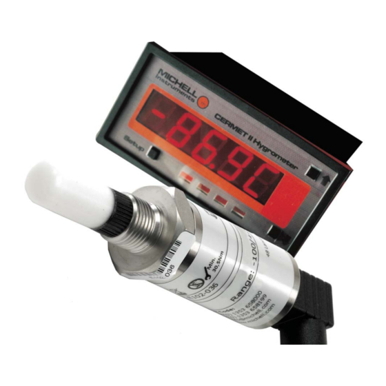
- Page 1 Cermet II Hygrometer User’s Manual 97049 Issue 25.3 October 2016...
- Page 2 Please fi ll out the form(s) below for each instrument that has been purchased. Use this information when contacting Michell Instruments for service purposes. Instrument Code Serial Number Invoice Date Location of Instrument Tag No Instrument Code Serial Number Invoice Date...
- Page 3 © 2016 Michell Instruments This document is the property of Michell Instruments Ltd. and may not be copied or otherwise reproduced, communicated in any way to third parties, nor stored in any Data Processing System without the express written authorization of Michell Instruments Ltd.
-
Page 4: Table Of Contents
Warnings ........................... vii INTRODUCTION ....................1 Features ......................1 INSTALLATION ....................2 Unpacking the Instrument ................... 2 2.1.1 Unpacking the Cermet II Transmitter .............. 3 2.1.2 Unpacking the Cermet II Monitor ..............4 2.1.3 Accessories Pack ..................4 Cermet II Components ..................5 Monitor ...................... - Page 5 Cermet II User’s Manual Figures Figure 1 Unpacking - Monitor and Accessories ............2 Figure 2 Transmitter Unpacking Method ..............3 Figure 3 Unpacking - Monitor ...................4 Figure 4 Unpacking - Accessories Pack ..............4 Figure 5 Components ....................5 Figure 6 Control Layout and Functions ..............6 Figure 7 Connector Terminal Block Removal ..............7...
-
Page 6: Safety
Michell Instruments’ worldwide offi ces contact information. Calibration The recommended calibration interval for the Cermet II transmitter is 12 months unless it is to be used in a mission-critical application or in a dirty or contaminated environment in which case the calibration interval should be reduced accordingly. -
Page 7: Abbreviations
Cermet II User’s Manual Abbreviations The following abbreviations are used in this manual: alternating current pressure unit (atmosphere) barg pressure unit (=100 kP or 0.987 atm) (gauge) direct current European Union grams per cubic meter Hertz pound lbs/MMSCF pounds per million standard cubic feet... -
Page 8: Introduction
The system comprises a programmable monitor confi gured to accept a unique Michell data string from the Cermet II transmitter. The zero and span of the monitor are set to cover the dew-point range -100 to +20°Cdp (-148 to +68°Fdp) at operating pressures up to 45 MPa (450 barg / 6500 psig). -
Page 9: Installation
It is essential that the connection of electrical and gas supplies to this instrument be undertaken by competent personnel. Unpacking the Instrument The Cermet II hygrometer and accessories are packed in a box and the method of unpacking is shown as follows: Figure 1 Unpacking - Monitor and Accessories 97049 Issue 25.3, October 2016... -
Page 10: Unpacking The Cermet Ii Transmitter
Cermet II User’s Manual INSTALLATION 2.1.1 Unpacking the Cermet II Transmitter On delivery, check that all the following standard components are in the packing tube: • Cermet II Transmitter • Bonded Seal • Certifi cate of Calibration Unpack the dew-point transmitter tube as follows:... -
Page 11: Unpacking The Cermet Ii Monitor
Cermet II User’s Manual INSTALLATION 2.1.2 Unpacking the Cermet II Monitor The monitor (2) is packed, together with its fi xing clamps (1) as shown below. Figure 3 Unpacking - Monitor 2.1.3 Accessories Pack The accessories pack is shown below:... -
Page 12: Cermet Ii Components
Cermet II User’s Manual INSTALLATION Cermet II Components On delivery, please check that all the following standard components are present in the packing box. Report any shortages immediately. Figure 5 Components Cermet II Monitor Clamps Transmitter cable assembly Cermet II Transmitter... -
Page 13: Monitor
Cermet II User’s Manual INSTALLATION Monitor The monitor has a 5-digit display, set-up on delivery to display a dew-point temperature range of -100° to +20°Cdp (-148° to +68°Fdp). Dew-point temperature units are displayed by the last LED located to the far right of the display. -
Page 14: Preparation Of The Transmitter Cable
The cable is pre-wired so no user wiring is required. If the cable needs to be re-wired, see below: Cable connection to the Cermet II transmitter is made via the removable connector. Removing the central screw enables the connector terminal block to be removed from the outer housing by using a small screwdriver to prise it clear. -
Page 15: Transmitter Mounting
Cermet II User’s Manual INSTALLATION Transmitter Mounting Prior to installation of the transmitter, unscrew and remove the blue plastic cover and retain for future use. Take care to prevent any contamination of the transmitter before installation (handle the transmitter by the main body only, avoiding contact with the sensor guard). -
Page 16: Transmitter Mounting - Sample Block And Gas Connections (Optional)
⅛” NPT female process connections. Tube adaptors are not supplied with the equipment but can be obtained by contacting your local distributor or Michell Instruments (see www.michell.com for details). Cut a suitable length of 6mm (¼” U.S.) stainless steel tubing (1) to the correct length and, if necessary, bend to shape to suit the location of the sensor block assembly. -
Page 17: Figure 9 Transmitter Mounting - Sensor Block
Cermet II User’s Manual INSTALLATION Push the stainless steel tubing (1) as far as it will go into the adaptor (5) and tighten up the locking nut (2) fi nger tight. Hold the adaptor (5) fl ats with a spanner and tighten up the locking nut (2) to a torque setting of 35 Nm (25 lbf-ft) (1¼... -
Page 18: Transmitter Mounting - Direct Pipeline Connection
Cermet II User’s Manual INSTALLATION 2.6.2 Transmitter Mounting - Direct Pipeline Connection The transmitter may be directly mounted into a pipe or duct, as shown in Figure 10. CAUTION: Do not mount the transmitter too close to the bottom of a bend where any condensate in the pipeline might collect and saturate the probe. -
Page 19: Transmitter Mounting - With Additional Process Connection Adapter
Cermet II User’s Manual INSTALLATION 2.6.3 Transmitter Mounting - With Additional Process Connection Adapter The following procedure must be carried out by a qualifi ed installation engineer. To mount the adapter into the transmitter, proceed as follows (see Figure 11) : 1. -
Page 20: Monitor Mounting
Cermet II User’s Manual INSTALLATION Monitor Mounting The monitor is designed for panel mounting and requires a panel cut-out of 46 x 92mm (1.8 x 3.6”). The recommended panel thickness is 2 to 5mm (0.08 to 0.2”). To mount the unit, proceed as follows:... -
Page 21: Electrical Connections
Cermet II User’s Manual INSTALLATION Electrical Connections The power supply voltage is indicated on the connection detail label located on the monitor. As the monitor is provided for continuous operation it does not have an ON/ OFF switch. The power supply to the monitor may be one of the following, dependant on the type ordered. -
Page 22: Low Voltage Power Supply Input
Cermet II User’s Manual INSTALLATION 2.8.2 Low Voltage Power Supply Input For low voltage powered display • 18 to 36 V AC and 9 to 60 V DC Connect the power supply to the monitor (1) as shown in Figure 14. -
Page 23: Transmitter Cable Connection
Cermet II User’s Manual INSTALLATION 2.10 Transmitter Cable Connection The diagram below shows the identity of the connector terminals. YELLOW Signal (A) YELLOW GREEN GREEN GREEN Signal (B) Signal (B) PIN 1 BLUE BLUE Ground PIN 3 BLUE Ground RED +Power... -
Page 24: Operation - Monitor
Cermet II User’s Manual OPERATION OPERATION - MONITOR NOTE: When the instrument is fi rst powered up the display may show a zero OPEN value for about 1 second, followed by a fl ashing for approximately 5 seconds, before showing a dew-point value. This is normal and does not indicate a problem with the instrument. -
Page 25: Selecting The Engineering Units
Cermet II User’s Manual OPERATION Selecting the Engineering Units PROGRAM UNLOCK Enter the mode (Section 3.1). SETUP Press and to scroll through the menus. The monitor can display Dew point in °C or °F, PPM(V), lbs/MMSCF or g/m3 (Natural... -
Page 26: Hysteresis, Make/Break Delay & Delay Type
Cermet II User’s Manual OPERATION Hysteresis, Make/Break delay & delay type Associated with each setpoint is a Hysteresis Value, Make delay time, Break delay time and a Delay type. To gain access to these parameters, set SPC_n = xx7, and scroll to the features by pressing the ... -
Page 27: Display Brightness Adjustment
Cermet II User’s Manual OPERATION Display Brightness Adjustment To adjust the display brightness press the SETUP and buttons simultaneously. The display toggles between [ ] and [ ], where 5 is the default setting. Adjust the display brightness required (from 0 to 7) by pressing the ... -
Page 28: Pressure Compensation
Cermet II User’s Manual OPERATION Register Address The register address for the read/write operation is specifi ed next. It can be either an ASCII number from registers 1 - 18 can be accessed by entering and ASCII letter from , not case sensitive). If the address character is omitted in a read command, the meter will always respond with the data value currently on the display. -
Page 29: Manual Pressure Input Calibration
Cermet II User’s Manual OPERATION 3.9.1 Manual Pressure Input Calibration The pressure input channel must be confi gured to the range of the pressure transducer. OFF_2 This is achieved by setting to 012 and entering values for offset and scale... -
Page 30: Using A Fixed Pressure Input In Single Channel Mode
Cermet II User’s Manual OPERATION 3.11 Using a Fixed Pressure Input in Single Channel Mode In order to display pressure compensated values of ppm without the use of a pressure transducer, enter the pressure value manually. PROGRAM UNLOCK Enter the mode (see Section 3.1). -
Page 31: Operation - Transmitter
fi lter, as a minimum level of protection. For more demanding applications Michell Instruments offers a range of sampling systems (for more information contact www.michell.com). -
Page 32: Maintenance
MAINTENANCE Calibration Routine maintenance of the Cermet II Transmitter is confi ned to regular re-calibration by exposure of the transmitter to sample gases of known moisture content to ensure that the stated accuracy of the transmitter is maintained. Calibration services traceable to the UK National Physical Laboratory (NPL) and the US National Institute of Standards and Technology (NIST) are provided by Michell Instruments. - Page 33 Cermet II User’s Manual APPENDIX A Appendix A Technical Specifi cations 97049 Issue 25.3, October 2016...
-
Page 34: Appendix A Technical Specifi Cations
Cermet II User’s Manual APPENDIX A Appendix A Technical Specifi cations Monitor 5 digit LED Display 7-segment digit, 14.2 mm(0.56”) Display Color Temperature and Alarm Red LED’s Indicators Performance Specifi cations Measurement Ranges -19999 to 99999 Dew point ±0.5°C (±1.0°F) - Page 35 Cermet II User’s Manual APPENDIX A Transmitter Performance Specifi cations Measurement Range -100 to +20°Cdp (-148 to +68°Fdp) dew point ±1°C dew point (+20 to -60°C) (+68 to -76°F) Accuracy ±2°C dew point (-60 to -110°C) (-76 to -166°F) Response Time...
- Page 36 Cermet II User’s Manual APPENDIX B Appendix B Setup Codes Michell Instruments...
-
Page 37: Appendix B Setup Codes
Cermet II User’s Manual APPENDIX B Appendix B Setup Codes Calibration modes for input and output DEFAULT VALUE = 052 Digit 1st digit (left most) 2nd digit 3rd digit Calibration Mode Calibration Function Object for Calibration Calibration functions as No function... - Page 38 Cermet II User’s Manual APPENDIX B CODE 4 Channel 1 Measurement task, Sampling rate DEFAULT VALUE = 207 Digit 1st digit (left most) 2nd digit 3rd digit Analog Sample Rate Analog Output 1 Source 0 only (No Function) Dew point in degrees C...
- Page 39 Cermet II User’s Manual APPENDIX C Appendix C Register Settings Accessible by Digital Communication 97049 Issue 25.3, October 2016...
-
Page 40: Appendix C Register Settings Accessible By Digital Communication
Cermet II User’s Manual APPENDIX C Appendix C Register Settings Accessible by Digital Communication Register Function Read Only Number Alarm Status Processed Data – Result Processed Data – Channel 1 (dew-point) Processed Data – Channel 2 (pressure) ... - Page 41 Cermet II User’s Manual APPENDIX C Code 4 Code 5 Code 6 Code 7 Code 8 138 to 141 Reserved Setpoint 1 Control Register Setpoint 2 Control Register Setpoint 3 Control Register Setpoint 4 Control Register 146 to 147 Brightness...
- Page 42 Cermet II User’s Manual APPENDIX D Appendix D EU Declaration of Conformity Michell Instruments...
-
Page 43: Appendix Deu Declaration Of Conformity
Cermet II User’s Manual APPENDIX D Appendix D EU Declaration of Conformity 97049 Issue 25.3, October 2016... - Page 44 APPENDIX E Cermet II User’s Manual Appendix E Quality, Recycling & Warranty Information Michell Instruments...
-
Page 45: Appendix E Quality, Recycling & Warranty Information
The directives’ aim is to reduce the impact that electronic devices have on the environment. Michell Instruments is in full compliance with the WEEE Directive and is registered with an approved recycler (Registration No. WEE/JB0235YW) and treats the requirement of the directive and the protection of the environment with the utmost importance. -
Page 46: Rohs2 Compliance
Equipment product sold into the EU market place as 22nd July 2017. However, the careful design policy of all Michell Instruments’ products continues to attain compliance in the shortest practical timescales and strives to ensure that less than 0.1% of total mass per product, of all non-compliant materials, appear within them. -
Page 47: Reach Compliance
Our continued review of the SVHC Candidate List and latest additions is to ensure we remain compliant. Michell Instruments maintains a hazardous material register in which MSDS data sheets are collated, and we will check that our suppliers will comply to REACH requirements for all materials and substances we use in the processes of our manufacturing. -
Page 48: Calibration Facilities
APPENDIX E Cermet II User’s Manual Calibration Facilities Michell Instruments’ calibration facilities are among the most sophisticated in the world and have been recognized for their excellence. Traceability to the National Physical Laboratory (NPL) UK is achieved through our UKAS Accreditation (Number 0179). - Page 49 APPENDIX F Cermet II User’s Manual Appendix F Return Document & Decontamination Declaration 97049 Issue 25.3, October 2016...
-
Page 50: Appendix F Return Document & Decontamination Declaration
Has the equipment been cleaned and decontaminated? NOT NECESSARY Michell Instruments will not accept instruments that have been exposed to toxins, radio-activity or bio-hazardous Work will not be carried out on any unit that does not have a completed decontamination declaration. - Page 51 Cermet II User’s Manual NOTES: 97049 Issue 25.3, October 2016...
- Page 52 http://www.michell.com...
Need help?
Do you have a question about the Cermet II and is the answer not in the manual?
Questions and answers