Table of Contents
Advertisement
Quick Links
Advertisement
Table of Contents

Subscribe to Our Youtube Channel
Related Manuals for Michell Instruments Liquidew I.S.


Summary of Contents for Michell Instruments Liquidew I.S.
- Page 1 Liquidew I.S. Process Moisture Analyzer User Manual 97092 Issue 6 July 2022...
- Page 2 Please fill out the form(s) below for each instrument that has been purchased. Use this information when contacting Michell Instruments for service purposes. Product Name Order Code Serial Number Invoice Date Installation Location Tag Number Product Name Order Code Serial Number...
- Page 3 © 2022 Michell Instruments This document is the property of Michell Instruments Ltd and may not be copied or otherwise reproduced, communicated in any way to third parties, nor stored in any Data Processing System without the express written authorization of Michell Instruments Ltd.
-
Page 4: Table Of Contents
Liquidew I.S. User Manual Contents Safety ..............................vi Electrical Safety ........................vii Pressure Safety ........................vii Hazardous Materials (WEEE, RoHS3 & REACH) ................vii Repair and Maintenance......................vii Calibration ..........................vii Safety Conformity ........................vii Abbreviations ..........................viii Warnings ............................viii INTRODUCTION ......................1 Performance Features ..................... 2 Applications ........................ - Page 5 Special Conditions ..................50 Maintenance and Installation ..............50 Appendix D System Drawings ....................52 Baseefa Approved System Drawing ............52 QPS Approved System Drawing ...............53 Appendix E Quality, Recycling & Warranty Information ..............55 Appendix F Return Document & Decontamination Declaration ...........57 Michell Instruments...
-
Page 6: Safety
Liquidew I.S. User Manual Safety The instrument is designed to be completely safe when installed and operated correctly in accordance with the information provided in this manual. This manual contains all the required information to install, operate and maintain this product. Prior to installation and use of this product, this entire manual should be read and understood. -
Page 7: Electrical Safety
Michell Instruments can offer a variety of re-calibration and exchange transmitter schemes to suit your specific needs. A local representative will be pleased to provide detailed custom advice. -
Page 8: Abbreviations
Liquidew I.S. User Manual Abbreviations The following abbreviations are used in this manual: Ampere alternating current barg pressure unit (=100 kP or 0.987 atm) gauge °C degrees Celsius °F degrees Fahrenheit direct current dew point gallons per minute ” inch(es) lbf-ft pound force per foot l/min... -
Page 9: Introduction
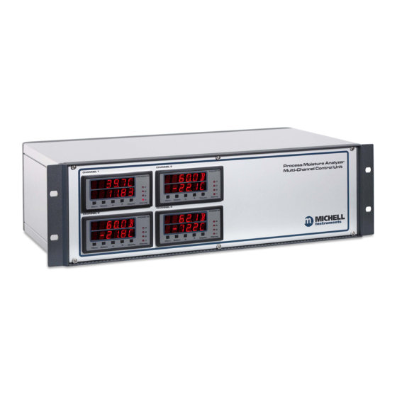
Zone 1 or Zone 2 (Class I, Division 1, Groups A, B, C & D) hazardous area. The control unit and transmitters are connected via a standard 2-wire instrumentation cable protected by safety isolation interface units. Figure 1 Liquidew I.S. Control Unit Michell Instruments... -
Page 10: Performance Features
Liquidew I.S. User Manual INTRODUCTION Performance Features • State-of-the-art ceramic metal-oxide moisture sensor with chemically inert materials coupled with physical resilience provides long-term reliability in the most arduous applications. Robust construction is exceedingly durable in liquid. Not affected by pressure shocks. •... -
Page 11: Theory Of Operation
• their own sources • laboratory analysis of process samples • estimated values from proportional calculation based on the values for each of the major components in the solute mix Michell Instruments... -
Page 12: System Components
Liquidew I.S. User Manual INTRODUCTION System Components The Liquidew I.S. Process Moisture Analyzer consists of: • the sensor assembly • the multi-channel control unit Sensor Assembly Control Unit (Up to four channels can have any combination of Liquidew I.S., Promet I.S. or Minox-i O sensors*) Temperature transmitter Sensor block... -
Page 13: Input/Output Signal
Maximum pressure: 5 MPa (50 barg / 725 psig) • Flow rate: 0.1...0.3 l/min (0.026...0.079 GPM) NOTE: Contact Michell Instruments if you wish to order a specific sampling system. Please refer to the ES70L Premium Sampling System Instructions if a Michell sampling system has been ordered with the Liquidew I.S. -
Page 14: Installation
Liquidew I.S. User Manual INSTALLATION INSTALLATION It is essential that the installation of the electrical and liquid supplies to this analyzer be undertaken by suitably qualified personnel. Unpacking the Analyzer Unpack carefully as follows: Remove the accessories (if ordered). If no accessories have been ordered the delivery should contain following items: •... -
Page 15: Environmental Requirements
NOTE: The materials and construction of the control unit allow for operation in an indoor, clean, non-hazardous only, control room environment. Figure 4 Dimensions of the Control Unit (in mm) Michell Instruments... - Page 16 Liquidew I.S. User Manual INSTALLATION Figure 5 Rack Mounting Method Figure 5 illustrates the general method for fitting a rack mount instrument into a standard 19” rack. To fit the unit proceed as follows: Remove all terminal blocks for the electrical connections. If necessary, remove any covers from the rack cabinet to gain access to the rear and side.
-
Page 17: Mounting The Liquidew I.s. Sensor Assembly Into The Sampling System
Finger-tighten the dew-point transmitter by gripping the spanner/wrench flats on the body - NOT the transmitter body cover. Completely tighten using a spanner/wrench until the bonded seal is fully compressed to a minimum torque of 30.5 Nm (22.5 lbf-ft). Michell Instruments... - Page 18 Liquidew I.S. User Manual INSTALLATION The temperature transmitter has a 6mm diameter probe. It is suitable for installing into the 1/8” NPT female port at the other end of the sensor block, by using the Swagelok 6mm to 1/8” NPT, ordering code SS- ®...
-
Page 19: Sampling System Installation
Connect the liquid inlet and outlet tubing to the fittings of the inlet/ outlet ports on the sampling system. If the sampling system has been ordered from Michell Instruments, the fitting is a 6mm or 1/4” Swagelok ® bulkhead union. Follow standard Swagelok installation instructions when ®... -
Page 20: Wiring
Liquidew I.S. User Manual INSTALLATION Wiring These tasks are to be undertaken only by suitably qualified personnel. All the connections to the rear panel are electrical connections. Exercise due caution, particularly when connecting to external alarm circuits which could be at high potential. -
Page 21: Control Unit Wiring
ALL OTHER CONNECTORS MUST NOT BE CONNECTED TO CABLES FROM HAZARDOUS AREA NOTE: Make sure channels are connected correctly. Connections for each channel are identical. The following text will only refer to one channel. Figure 8 Control Unit Electrical Connections Michell Instruments... -
Page 22: Power Supply Input Connection
Liquidew I.S. User Manual INSTALLATION 2.4.2.1 Power Supply Input Connection 85...265 V AC POWER INPUT The AC power supply connection is a push fit socket labelled as shown below. POWER INPUT Socket IEC connector Figure 9 POWER INPUT Socket The method of connection is as follows: Turn off the AC power. -
Page 23: Figure 10 Power Input Connector Block
Connect the free end of the power cable to a suitable DC power supply source (voltage range 18...28 V DC). The instrument may then be switched on, as required, by the power switch at the source. Michell Instruments... -
Page 24: Sensor Signal Input Connection
Liquidew I.S. User Manual INSTALLATION 2.4.2.2 Sensor Signal Input Connection HAZARDOUS AREA INFORMATION Cables from transmitters mounted in hazardous areas can be SENSOR INPUTS connected directly to the connector block. There are built-in Galvanic I.S. barriers for all connections made to this connector block. -
Page 25: Analog Output Connection
Insert the -ve (4...20 mA) wire into the terminal way on the terminal block and tighten the screw. Check that the wiring has been completed correctly. OUTPUT Push the terminal block firmly back into the socket. Michell Instruments... -
Page 26: Alarm Output Connection
Liquidew I.S. User Manual INSTALLATION 2.4.2.4 Alarm Output Connection Four alarm output ports are provided and are connected to the instrument via a single 8-way push fit connector block labelled ALARMS as shown below. ALARMS socket Terminal bock Figure 12 ALARM Connector Block Alarm 1 (connection labelled as AL1) and Alarm 2 (connection labelled as AL2) are Form... -
Page 27: Rs485 Port Connection
The RS485 connection is a push-fit 9-pin socket as shown in Figure 8 . The method of connection is as follows: Pin Number Function Check the orientation of the RS485 connector and gently push it into the socket. Tighten the two screws on the connector. Michell Instruments... -
Page 28: Sensor Assembly Wiring
Liquidew I.S. User Manual INSTALLATION 2.4.3 Sensor Assembly Wiring NOTE: If the analyzer has been ordered with a sampling system, the Liquidew I.S. sensor assembly will be factory-wired to the junction box. In that case disregard the following instructions and go to Section 3. 2.4.3.1 Dew-point Transmitter Wiring HAZARDOUS AREA INFORMATION The dew-point transmitter (Easidew PRO I.S.) is certified... -
Page 29: Figure 14 Cut To 5 Mm
Cut to 5 mm Cable connection to the dew-point transmitter is made via the terminal block (4) (see Figure 15) . Remove the terminal housing lid (2) to access. Figure 15 Dew-Point Transmitter Housing Michell Instruments... -
Page 30: Figure 16 Dew-Point Transmitter Pin Assignment Drawing
Liquidew I.S. User Manual INSTALLATION Ensure that the outer diameter of the selected cable is matched to an EExe M20 cable gland (5). Unscrew the cable gland (5) and slide the cable through the cable gland (5) and into the terminal housing (1) through the cable entry (3). -
Page 31: Temperature Transmitter Wiring
Ensure that the outer diameter of the selected cable is matched to an EExe M20 cable gland (5). Unscrew the cable gland (5) and slide the cable through the cable gland (5) and into the terminal housing (1) through the cable entry (3). Michell Instruments... - Page 32 Liquidew I.S. User Manual INSTALLATION Connect the signal cable leads to the terminals on the terminal block (4) in accordance with the following pin-assignment drawing. Pin designations are marked adjacent to each pin. SENSOR INPUTS Block Dew Point Temp Supply + 4-20 mA lead 4-20 mA - 4-20 mA lead...
-
Page 33: Operation
The main display shows a humidity and a temperature value, the status of four alarms and a display locked/unlocked symbol. The upper value will always represent a humidity and the lower the temperature value from a temperature transmitter. Michell Instruments... -
Page 34: Setup Menu
Liquidew I.S. User Manual OPERATION To change the displayed humidity value LOCK Press the icon and enter the passcode (5618) using the keypad. Then press the upper value to toggle between dew point and moisture concentration in . The selected liquid will be displayed next to the padlock, as shown below (e.g. n-butane). - Page 35 Dew Point, Temperature or Moisture (ppm ), whereby the units for Dew Point and Temperature are set in the Display Menu. Defaults: • OP1 = Dp (-100.0...+20.0) • OP2 = Temperature (0.0...+50.0) • OP3 = Moisture (0.0...+100.0) Michell Instruments...
- Page 36 Liquidew I.S. User Manual OPERATION Display Menu The display menu is used to: • Select the units for Dew Point and Temperature (°C or °F). Default = °C • Set the Modbus address. Default = 1 Inputs Menu Used to change to range of the Dew Point and Temperature input in the units set in the display menu.
- Page 37 Liquids Menu These menu pages allow the user to select the required liquid for the ppm calculation. Page 3 allows the user to edit the two user pages: whereby the Cs values for a particular liquid can be inputted. Michell Instruments...
- Page 38 Liquidew I.S. User Manual OPERATION The MIXING page allows the user to mix any of the predetermined liquids or the User settable liquids as a ratio. About 97092 Issue 6, July 2022...
-
Page 39: Menu Structure
Save Setting before exiting menu Transducer Fixed Value Fixed Pressure Value in the units selected in the Display menu; used for operation without a pressure transducer to calculate moisture concentration values. Save Setting before exiting menu Michell Instruments... -
Page 40: Figure 19 Menu Map
Liquidew I.S. User Manual OPERATION PUV = Press Upper Valu Dp PUV ppmV(I) Select Alarm Pressure ppmV(I) Save Setting for exiti Select Output Pressure ppmV(I) Save Setting before e Temperature Unit (C or F) for both Inputs and Outpu ISO & IGT selection for Na Save Setting before e Sets the 4-20mA range fo Transmitters, which are in... -
Page 41: Appendix A Technical Specifications
Liquidew I.S. User Manual APPENDIX A Appendix A Technical Specifications Michell Instruments... - Page 42 Liquidew I.S. User Manual APPENDIX A Appendix A Technical Specifications Sensors Sensor Technology Michell Ceramic Metal-Oxide Moisture Sensor Sensor Version Easidew PRO I.S. 0.001...1000 ppm Higher range on request Measurement Range Actual range dependent on solubility of sample fluid Calibration Range -100...+20 °Cdp (-148...+68 °Fdp) Dew point: ±1 °C from -59.9 to +20 °Cdp...
-
Page 43: Dimensional Drawings
Liquidew I.S. User Manual APPENDIX A Premium Sampling Systems Refer to relevant ES70L data sheet (97550) Hazardous Area Certification Certification Codes See Appendix D Dimensional Drawings Figure 20 Dimensional Drawings (in mm) Michell Instruments... -
Page 44: Appendix B Serial Communications
Liquidew I.S. User Manual APPENDIX B Appendix B Serial Communications 97092 Issue 6, July 2022... - Page 45 Pin numbers in the manual refer to standard pins on the DB9 D-Sub connector on the rear panel of the MCU: Male DB9 Pinout (Liquidew I.S. Monitor on MCU Panel) It will be necessary to match up the A/B (Differential data pair) and GND (0 V) pins with the wiring of your own third party adaptor. Michell Instruments...
- Page 46 Liquidew I.S. User Manual APPENDIX B Process Monitor Register Map: Read/ Default Register Address Function Description Notes Write Value Configuration Modbus Address 1...32 Alarm Configuration mA output Configuration System Configuration O/p 1 low s/p hi word FLOAT O/p 1 low s/p lo word FLOAT O/p 1 high s/p hi word FLOAT...
- Page 47 0...4095 20mA Pressure (P) /Tempr (L) Channel – ADC Val 4mA (n/a for O 0...4095 only) Pressure (P) /Tempr (L) Channel – ADC Val 20mA (n/a for 0...4095 only) Analog Output 1 – DAC 4 mA Value 0...65535 Michell Instruments...
- Page 48 Liquidew I.S. User Manual APPENDIX B Read/ Default Register Address Function Description Notes Write Value Configuration Analog Output 1 – DAC 20 mA 0...65535 Value Analog Output 2 – DAC 4 mA Value 0...65535 Analog Output 2 – DAC 20 mA 0...65535 Value Analog Output 3 –...
- Page 49 IEEE754 as float – Lo Word Pressure / Temp. in set unit IEEE754 as float – Hi Word (n/a for O only) Pressure / Temp. in set unit IEEE754 as float – Lo Word (n/a for O only) Michell Instruments...
- Page 50 Liquidew I.S. User Manual APPENDIX B Register Configuration A A1: Unsigned Short. Range = 0...65535 A2: Unsigned Short /10. Range = 0...6553.5 A3: Unsigned Short /100. Range = 0...655.35 Conversion: float*x = unsigned integer Unsigned integer/x = float Or cast: float value to read= ((float) (value))/x;...
- Page 51 0010 = ppm 0011 = ppm (Ideal) 0011 = ppm (Ideal) 0100 = ppm (Nat Gas) 0100 = ppm (Nat Gas) 0101 = mgm 0101 = mgm 0110 = lbmmscf 0110 = lbmmscf 1000 = Fault 1000 = Fault Michell Instruments...
- Page 52 Liquidew I.S. User Manual APPENDIX B Register Configuration E – mA Output Config Ouput1 Parameter (O1) Output2 Parameter (O2) Output3 Parameter (O3) 0000 = Dew point (O2) 0000 = Dew point (O2) 0000 = Dew point (O2) 0001 = Pressure/ 0001 = Pressure/ 0001 = Pressure/ Temperature...
- Page 53 25 = Send Test String to Display Comms Channel 30 = Set control board to default register map values 31 = Enable Setup Mode (Alarms and Analog output updates disabled) 32 = Disable Setup Mode (Alarms and Analog output updates enabled) Michell Instruments...
- Page 54 Liquidew I.S. User Manual APPENDIX B Defaults (auto-loaded when PCB is brand new or forced via Modbus) Modbus ID System config. Main unit = °CDp, temp. unit = °C Alarm config. AL1 = Moisture (low = 0.0, high = 100.0) AL2 = Moisture (low = 0.0, high = 10.0) AL3 = FAULT (low = high = 0.0) AL4 = FAULT (low = high = 0.0)
-
Page 55: Appendix C Hazardous Area Certification
Liquidew I.S. User Manual APPENDIX C Appendix C Hazardous Area Certification Michell Instruments... -
Page 56: Product Standards
Liquidew I.S. User Manual APPENDIX C Appendix C Hazardous Area Certification The Liquidew I.S. Process Moisture Analyzer utilizes the Easidew PRO I.S. dew-point transmitter The Easidew PRO I.S is certified compliant to the ATEX Directive (2014/34/EU), the IECEx scheme and SI 2016 No. 1107 UKCA product marking scheme for use within Zone 0, 1 and 2 Hazardous Areas and has been assessed as being so by CML Bv Netherlands (Notified Body 2776) and EUROFINS CML UK (Approved Body 2503). -
Page 57: Terminal Parameters
The Easidew PRO I.S. must only be installed by suitably qualified personnel and in accordance with the instructions provided and the terms of the applicable product certificates. Maintenance and servicing of the product must only be carried out by suitably trained personnel or returned to an approved Michell Instruments Service Center. Michell Instruments... -
Page 58: Appendix D System Drawings
Liquidew I.S. User Manual APPENDIX D Appendix D System Drawings 97092 Issue 6, July 2022... -
Page 59: Baseefa Approved System Drawing
Liquidew I.S. User Manual APPENDIX D Appendix D System Drawings Baseefa Approved System Drawing Michell Instruments... -
Page 60: Qps Approved System Drawing
Liquidew I.S. User Manual APPENDIX D QPS Approved System Drawing 97092 Issue 6, July 2022... -
Page 61: Appendix E Quality, Recycling & Warranty Information
Liquidew I.S. User Manual APPENDIX E Appendix E Quality, Recycling & Warranty Information Michell Instruments... - Page 62 Liquidew I.S. User Manual APPENDIX E Appendix E Quality, Recycling & Warranty Information Michell Instruments is dedicated to complying to all relevant legislation and directives. Full information can be found on our website at: www.michell.com/compliance This page contains information on the following directives: •...
-
Page 63: Appendix F Return Document & Decontamination Declaration
Liquidew I.S. User Manual APPENDIX F Appendix F Return Document & Decontamination Declaration Michell Instruments... - Page 64 Has the equipment been cleaned and decontaminated? NOT NECESSARY Michell Instruments will not accept instruments that have been exposed to toxins, radio-activity or bio-hazardous materials. For most applications involving solvents, acidic, basic, flammable or toxic gases a simple purge with dry gas (dew point <-30°C) over 24 hours should be sufficient to decontaminate the unit prior to return.
- Page 65 Liquidew I.S. User Manual NOTES Michell Instruments...
- Page 66 www.ProcessSensing.com http://www.michell.com...
Need help?
Do you have a question about the Liquidew I.S. and is the answer not in the manual?
Questions and answers