Table of Contents
Advertisement
PNG380
PNG381
PNG382
Automatic gate
type "PNG380/381/382"
FIELD MANUAL
Automatic Systems s.a.
Head office & factory:
Avenue Mercator 5, 1300 Wavre, Belgium
Tel.: 32-10-23.02.11 Fax: 32-10-23.02.02
Automatic Systems reserves the right to change the characteristics of its products without notice.
Automatic Systems PNG38X-A3_1-04-gb-02.doc
10/12/01
Field manual
Advertisement
Table of Contents

Related Manuals for Automatic Systems PNG382


Summary of Contents for Automatic Systems PNG382
- Page 1 FIELD MANUAL Automatic Systems s.a. Head office & factory: Avenue Mercator 5, 1300 Wavre, Belgium Tel.: 32-10-23.02.11 Fax: 32-10-23.02.02 Automatic Systems reserves the right to change the characteristics of its products without notice. Automatic Systems PNG38X-A3_1-04-gb-02.doc 10/12/01 Field manual...
-
Page 2: Table Of Contents
4.2.7. Variable speed controller management ..................26 4.2.8. Pictograms............................27 4.2.8.1. Limited mode ..........................27 4.2.8.2. Extended mode........................27 4.2.8.2.1. Orientation pictogram......................27 4.2.8.2.2. Function pictogram .......................27 4.2.8.2.3. "Passage authorization storage" configuration..............27 4.2.8.2.4. "No passage authorization storage" configuration ..............27 p. 2/51 Automatic Systems PNG38X-A3_1-04-gb-02.doc 10/12/01... - Page 3 Mounting and dismantling a mobile obstacle....................50 8.3.1. Dismantling .............................50 8.3.2. Mounting ............................50 MAINTENANCE ............................51 ANNEX 1: TECHNICAL DATA ANNEX 2: ELECTRICAL DIAGRAMS ANNEX 3: MECHANICAL SPARE PARTS ANNEX 4: RECOMMENDED MECHANICAL SPARE PARTS ANNEX 5: OBSTACLE IMPACT FORCES p. 3/51 Automatic Systems PNG38X-A3_1-04-gb-02.doc 10/12/01...
-
Page 4: Introduction
1. INTRODUCTION We thank you for choosing the "PNG380”, “PNG381”, or “PNG382" automatic gate designed and manufactured by Automatic Systems. We are confident that your purchase will fully meet your requirements. However, in order to obtain maximum satisfaction from this equipment for a maximum period of time, we strongly advise you to read this manual carefully before installing the equipment. -
Page 5: General
Conventionally and as a general rule, the user will be considered in direction "A" when the gate is at his right side, in direction "B" when the gate is at his left side. Direction A is typically the entry direction into the paid area, while direction B is the exit. p. 5/51 Automatic Systems PNG38X-A3_1-04-gb-02.doc 10/12/01... -
Page 6: Switching Off The Equipment
2.3. General conditions of use • Your automatic gate type “PNG380/381/382” has been designed to operate in any kind of climatic environment, from -20°C to +60°C, with up to 95% of relative humidity. p. 6/51 Automatic Systems PNG38X-A3_1-04-gb-02.doc 10/12/01... -
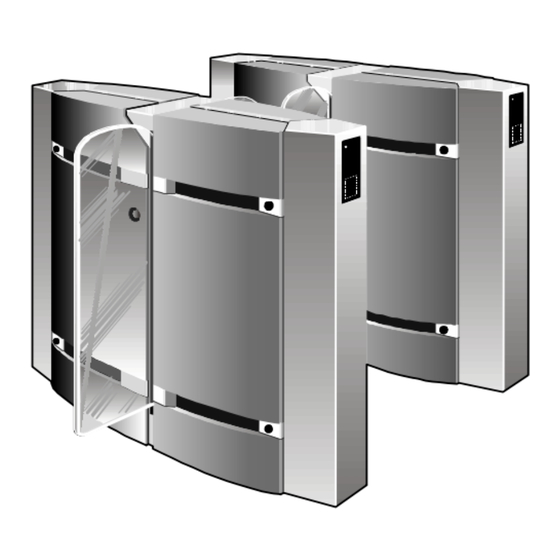
Page 7: Sectional Views
2.4. Sectional views Right type PNG382 (model shown: w/o fixed obstacle) Legend: 3:1 Mobile obstacle 3:6 Detection photocells 3:2 Balance spring 3:7 Hinged hoods 3:3 Driving shafts & pillow blocks 3:8 Frame 3:9 Earth bolt 3:4 Motor 3:5 Driving rods 2.5. -
Page 8: In Case Of Power Failure
4:8 Safety shutter 4:9 Rubber bumpers Note: Each obstacle is actuated by its own associated mechanical group. An intermediate element hence includes two mechanical groups, and an outer element (left or right) includes one. p. 8/51 Automatic Systems PNG38X-A3_1-04-gb-02.doc 10/12/01... -
Page 9: Sample Configuration
2.8. Sample configuration • The sample configuration below shows a four passage-way bidirectional PNG382/NC battery (reversible). The structure comprises two outer elements (1 and 5), and three intermediate elements (2, 3, and 4). Element 1 is of the left type, and element 5 of the right type. -
Page 10: General Dimensions And Installation Plans (With Cabling)
In all cases, ensure that cables have a minimum of 3 metres from the finished ground level. Prepare a wire puller between each adjacent gate. Supplied by Automatic Systems: • Connection between each adjacent gate in 4G1.5 type LIYCY (motor power supply). (Standard: 3m long) p. - Page 11 1700 1000 137.5 1300 Left gate Intermediate gate Right gate 1900 2005 Cabling: see p. 10 Plan No. CH3508 PNG380 with fixed obstacle p. 11/51 Automatic Systems PNG38X-A3_1-04-gb-02.doc 10/12/01...
- Page 12 1000 1700 1000 137.5 1000 1650 Left gate Intermediate gate Right gate Cabling: see p. 10 1900 2005 Plan No. CH3527 PNG381 p. 12/51 Automatic Systems PNG38X-A3_1-04-gb-02.doc 10/12/01...
- Page 13 1000 1700 1000 137.5 1000 1000 2000 Left gate Intermediate gate Right gate Cabling: see p. 10 1900 2005 Plan No. CH3520 PNG382 p. 13/51 Automatic Systems PNG38X-A3_1-04-gb-02.doc 10/12/01...
-
Page 14: Installation
• In the case of a PNG381 or PNG382, also unlock and open the hood(s) (10:5) and (10:6). • In the case of a PNG381 or PNG382, also unlock and remove the lateral extension door(s) (10:7) and (10:8). • Check the state of the material. Though it has been carefully packed, damage may have occurred during transport. -
Page 15: Preliminary Work On Site
FIXING BRACKET EXPANSIBLE BOLT B15/30 -/3413/000 (or equivalent) Min. 55 ♦ Preparation of the electrical power supply and control cabling according to the specifications in chapter [2.9. General dimensions and installation plans (with cabling)]. p. 15/51 Automatic Systems PNG38X-A3_1-04-gb-02.doc 10/12/01... -
Page 16: Installing The Gate
To ensure the proper operation of the gate, confirm that the obstacles are perfectly vertical and ARNING that the frame is not distorted, even slightly. 25 mm - 0.5 25 mm - 0.5 > 25 mm < 25 mm Légende: A = Fixing bracket B = Spacer p. 16/51 Automatic Systems PNG38X-A3_1-04-gb-02.doc 10/12/01... -
Page 17: Electrical Connections
13:1 Legend: 13:1 Geared motor 13:2 Geared motor connection block Connect the cable from the connector X6 according to the electrical diagram 1PNG04.013 for an intermediate gate or 1PNG04.014 for a left gate. p. 17/51 Automatic Systems PNG38X-A3_1-04-gb-02.doc 10/12/01... -
Page 18: Initial Power-Up
(2:1) at the end of the procedure. • Press RESET on the Programmable Logic Controller (PLC), which reactivates the initialization sequence. See the initialization sequence description in paragraph [4.5.1.]. p. 18/51 Automatic Systems PNG38X-A3_1-04-gb-02.doc 10/12/01... -
Page 19: Technical Section
The alarm will end when there is no longer any presence in any of the two entrance corridors (A and B) and after a short time-out (%TM0) (1 sec by default) "Intrusion" Fraud ALARM after 15 seconds Fig. 13a p. 19/51 Automatic Systems PNG38X-A3_1-04-gb-02.doc 10/12/01... -
Page 20: Tailgating" Fraud
Nota Bene: The “tailgating” fraud will only be operational with the default values for the extension corridor (PNG 381 or PNG382). “Tailgating” fraud before passage may be made operational for PNG 380 by modifying the parameter values %MW30, %MW21 and/or %MW22 to 1 but bear in mind that there will consequently be a significant risk of false alarms. -
Page 21: Opposite Direction" Fraud
A user presents a valid ticket and can enter the walkway in the controlled direction. While the doors are open, a person enters in the opposite direction in free mode. Two types of “opposite direction” detection are possible: p. 21/51 Automatic Systems PNG38X-A3_1-04-gb-02.doc 10/12/01... -
Page 22: Operation Modes
The doors close again in mode NF when corridor B has been freed and after a time-out (% TM1) (2 sec by default). Choice of the type of “opposite direction” detection will take place in this operation mode. (see 4.2.1.4.) p. 22/51 Automatic Systems PNG38X-A3_1-04-gb-02.doc 10/12/01... -
Page 23: Controlled Direction A - Locked Direction B
This latter contact may be defined NO or NF during the configuration procedure (DIP5 of word 3; this contact is NO by default. Evacuation mode is activated as long as the contact is maintained. p. 23/51 Automatic Systems PNG38X-A3_1-04-gb-02.doc 10/12/01... -
Page 24: Passage Authorizations
A passage authorization in the opposite direction will not be taken into account until the PNG has returned to its stand-by status. The "opposite direction" fraud is detected as long as the obstacle is not closed. p. 24/51 Automatic Systems PNG38X-A3_1-04-gb-02.doc 10/12/01... -
Page 25: Detection Of Passage Through Doors
PNG, and when the obstacles have been closed. In this event, authorization storage is not possible as the obstacles have to close after each person. This method slows down the flow but maximizes control. p. 25/51 Automatic Systems PNG38X-A3_1-04-gb-02.doc 10/12/01... -
Page 26: Locking Of The Card Reader
The choice of this DIP’s position is depending on the type of the variable speed what is installed in the PNG and on his activation mode. The appropriate position of the DIP is fixed by the factory. p. 26/51 Automatic Systems PNG38X-A3_1-04-gb-02.doc 10/12/01... -
Page 27: Pictograms
When an alarm is activated after the detection of a fraud, in limited mode, the orientation pictogram will display a “red cross” and in extended mode, the operation pictogram will display a “red cross”. p. 27/51 Automatic Systems PNG38X-A3_1-04-gb-02.doc 10/12/01... -
Page 28: Png Configuration
Press the L.C.A. push-button (2:11), wait for the validation signal and release the button. word 2. Set the DIP switches according to the tables below in order to configure 8.a. DIP 1 always at 0 p. 28/51 Automatic Systems PNG38X-A3_1-04-gb-02.doc 10/12/01... - Page 29 Evacuation if connection 5-6 of X13 is closed 10.f. Detection of opposite direction fraud in “Free exit” mode DIP 6 Configuration Reinforced detection “opposite direction” in “Free exit” mode Reduced detection “opposite direction” in “Free exit” mode p. 29/51 Automatic Systems PNG38X-A3_1-04-gb-02.doc 10/12/01...
- Page 30 14. Reconnect the connectors X15.Low, X13.High and X13.Low. 15. Switch on the variable speed controller power supply. 16. Switch on the PNG main power supply. From this moment on, the PNG is operational. p. 30/51 Automatic Systems PNG38X-A3_1-04-gb-02.doc 10/12/01...
-
Page 31: Time-Outs, Pulses And Variables
Time limit before opening the doors after cancellation of safety Period of contact: Pulse Name Time base Default value Description M_new_lc_a 100ms Passage pulse duration in direction A. %MN0 M_new_lc_b 100ms Passage pulse duration in direction B. %MN1 p. 31/51 Automatic Systems PNG38X-A3_1-04-gb-02.doc 10/12/01... - Page 32 0 : Detection of opposite direction entrance over 3 cells 1 : Detection of opposite direction entrance over 2 cells %M46 Ext_cel_a Cell extension – direction A: 0: absent (PNG380) 1: present (PNG381-PNG382) %M47 Ext_cel_b Cell extension –direction B: 0: absent (PNG380-PNG381) 1: present (PNG382)
-
Page 33: Adapting The Configuration Parameters
14. Type 0 or 1 followed by ENTER. 15. Select Menu. 16. Select Cnv then ENTER with the horizontal arrows. 17. Select Dec then ENTER with the vertical arrows. c) Adjusting the time-outs and monostables p. 33/51 Automatic Systems PNG38X-A3_1-04-gb-02.doc 10/12/01... -
Page 34: Visualization And Description Of Entries On The Plc
16.15 Safety extension Note: In order to display the inputs from I16.0 to I16.15 thanks to the PLC LEDs, press the « DIAG » button for less than one second until the digit 16 appears. p. 34/51 Automatic Systems PNG38X-A3_1-04-gb-02.doc 10/12/01... -
Page 35: Visualization And Description Of Entries On The Plc
16.15 Reserve 2 Note: In order to display the inputs from Q16.0 to Q16.15 thanks to the PLC LEDs, press the « DIAG » button for less than one second until the digit 16 appears. p. 35/51 Automatic Systems PNG38X-A3_1-04-gb-02.doc 10/12/01... -
Page 36: As1007 Interface Board
Passage contact direction A X13.7,8 Reader lock direction A X13.9,10 Connection block Passage contact direction B X13.17,18 Reader lock direction B X13.19,20 Factor setting JP1 JP2 JP5 JP6 JP7 JP8 NO Fig. 14a p. 36/51 Automatic Systems PNG38X-A3_1-04-gb-02.doc 10/12/01... - Page 37 X14.27 Alr fraud 2 X15.13 +24VDC X14.28 X15.14 +24VDC X15.15 X15.16 Fig. 14b Warning: If the safety bands are not installed on the PNG fixed glass, entrances X13.15 and X13.16 must be shunted. p. 37/51 Automatic Systems PNG38X-A3_1-04-gb-02.doc 10/12/01...
-
Page 38: Variable Speed Controller Configuration
As the risk for users is increased in this case, you might have to prohibit access to animals and unaccompanied children. p. 38/51 Automatic Systems PNG38X-A3_1-04-gb-02.doc 10/12/01... -
Page 39: Final Step
Remove any foreign body from the inside of the gate (scraps, etc.), and clean. In the case of a PNG381 or PNG382, replace and lock the lateral extension door(s) (10:7) and (10:8). In the case of a PNG381 or PNG382, close and lock the hood(s) (10:5) and (10:6). -
Page 40: Temporary Dismantling
Unlock and open the lateral, hinged polyester doors (10:1) to (10:4). In the case of a PNG381 or PNG382, also unlock and open the hood(s) (10:5) and (10:6). In the case of a PNG381 or PNG382, also unlock and remove the lateral extension door(s) (10:7) and (10:8). -
Page 41: Operation
6. OPERATION 6.1. System overview C7-C14 C7-C14 C6-C13 C6-C13 Left element Intermediate element Right element PNG382 battery PNG380 PNG381A PNG381B PNG382 DIRECTION B DIRECTION A p. 41/51 Automatic Systems PNG38X-A3_1-04-gb-02.doc 10/12/01... -
Page 42: General Principle Of Operation
These faults are visually indicated by LEDs on the fascia of the PLC, and generate a technical or fraud alarm signal (together with a standard audible signal) transmitted to the remote control desk (option). PNG380 PNG381 PNG382 All intermediate type gates p. 42/51 Automatic Systems PNG38X-A3_1-04-gb-02.doc 10/12/01... -
Page 43: Passage Of A Person
In the figure above, the user should keep his suitcase closer to himself, otherwise the PNG will consider this passage as a "tailgating" fraud attempt and set to fraud alarm status. The obstacles will close after the suitcase has passed. p. 43/51 Automatic Systems PNG38X-A3_1-04-gb-02.doc 10/12/01... - Page 44 44/51 Automatic Systems PNG38X-A3_1-04-gb-02.doc 10/12/01...
-
Page 45: Passage Of Two Persons With A Single Ticket
(Fig. 22 b), the doors will close before the first person can go through, except if the safety group is activated. Min. 2 cells activated Cell not activated = ALARM Cell not activated p. 45/51 Automatic Systems PNG38X-A3_1-04-gb-02.doc 10/12/01... -
Page 46: Information To Users
"Insert your card"; "Walk" or "Wait". Optionally, it can be replaced by a liquid crystal display expressing the messages in the language desired; the operation principle is identical. • This pictogram can be used with an orientation pictogram. p. 46/51 Automatic Systems PNG38X-A3_1-04-gb-02.doc 10/12/01... -
Page 47: Mechanical Adjustments And Interventions
Manually set the geared motor crank (24:1) to a distance of 40 mm from the closing abutment (lower rubber bumper). Loosen the two locking screws of the cam (24:2), and slightly move the cam in either direction until the limit switch is engaged (a click sound can then be heard). p. 47/51 Automatic Systems PNG38X-A3_1-04-gb-02.doc 10/12/01... - Page 48 • Proceed likewise with an obstacle closing cycle (passage-way free): the obstacle must be locked, with a minimum play, and with motor stopped. 0.1mm 25:1 Legend: 25:1 Closing limit switch (FCF) Passage-way free p. 48/51 Automatic Systems PNG38X-A3_1-04-gb-02.doc 10/12/01...
-
Page 49: Detection Photocell Adjustment
Even though the yellow LED of all cells is on, it is advisable to check their connection to the PLC, and make sure the corresponding LEDs are also on and go off whenever the cells are occulted. p. 49/51 Automatic Systems PNG38X-A3_1-04-gb-02.doc 10/12/01... -
Page 50: Mounting And Dismantling A Mobile Obstacle
Maintaining the obstacle 3 mm from the safety shutter, check the position of the obstacle with the help of a bubble level and progressively tighten the 5 screws (27:1) with a tightening torque of 10 to 11 Nm maximum. p. 50/51 Automatic Systems PNG38X-A3_1-04-gb-02.doc 10/12/01... -
Page 51: Maintenance
Unlock and open the lateral, hinged polyester doors (10:1) to (10:4). In the case of a PNG381 or PNG382, also unlock and open the hood(s) (10:5) and (10:6). In the case of a PNG381 or PNG382, also unlock and remove the lateral extension door(s) (10:7) and (10:8).
Need help?
Do you have a question about the PNG382 and is the answer not in the manual?
Questions and answers