Table of Contents
Advertisement
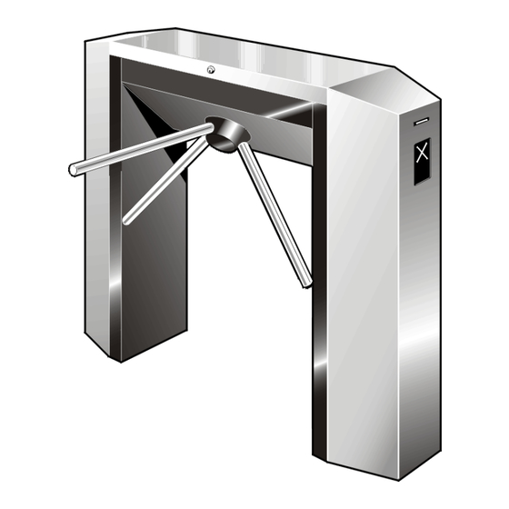
TR490 Tripod Turnstile
INSTALLATION MANUAL
Rev 05
Automatic Systems s.a.
Head office & factory:
Avenue Mercator 5, 1300 Wavre, Belgium
Tél.: 32-10-23.02.11 Fax: 32-10-23.02.02
Automatic Systems reserves the right to change the characteristics of its products without notice.
1/16
Automatic Systems
TR490-NInstall-EN
p
Advertisement
Table of Contents

Related Manuals for Automatic Systems TR490


Summary of Contents for Automatic Systems TR490
- Page 1 INSTALLATION MANUAL Rev 05 Automatic Systems s.a. Head office & factory: Avenue Mercator 5, 1300 Wavre, Belgium Tél.: 32-10-23.02.11 Fax: 32-10-23.02.02 Automatic Systems reserves the right to change the characteristics of its products without notice. 1/16 Automatic Systems TR490-NInstall-EN...
-
Page 2: Table Of Contents
11 3.7.2. Dismounting the tripod arms ................p. 11 3.7.3. Removing the unit ................... p. 12 3.8. Scrapping the equipment ....................p. 12 ELECTRICAL DIAGRAMS ....................p. 13 EC CERTIFICATE ......................p. 16 2/16 Automatic Systems TR490-NInstall-EN... -
Page 3: Introduction
INTRODUCTION We thank you for choosing the TR490 electrical tripod turnstile designed and manufactured by Automatic Systems. We are confident that your purchase will fully meet your requirements. However, in order to obtain maximum satisfaction from this equipment for a maximum period of time, we strongly advise you to read this manual carefully before installing the equipment. -
Page 4: General
Fig. 1 Note: Conventionally and as a general rule, the user will be considered in direction "A" when the turnstile is at his right-hand side, in direction "B" when the turnstile is at his left-hand side. 4/16 Automatic Systems TR490-NInstall-EN... -
Page 5: Switching Off The Equipment
In case of power failure Depending on which control mode the tripod is set up for, the TR490 tripod turnstile can release the mechanism in either direction or in both, when the electrical power supply is interrupted. This unlocking principle in an emergency situation is called the "anti-panic" device. -
Page 6: Overall Dimensions And Installation Plan
Power supply and command cable inlet area 1220 Cabling to be prepared: Power supply: 230V single-phase + earth (3G x 2.5) Control wiring according to specifications ° 15 EXPANSION BOLT B15/30 -/3413/000 (recommended model) min. 100 Fig. 3 6/16 Automatic Systems TR490-NInstall-EN... -
Page 7: Installation
Raise and remove the front columns (4:1) et (4:2). Check the state of the material. Though it has been carefully packed, damage may have occurred during transport. Any transportation damage should be repaired, or components replaced. 7/16 Automatic Systems TR490-NInstall-EN... -
Page 8: Preliminary Work On Site
Tighten the expansible bolts in order to fix the turnstile on the ground. Make sure that cables are not trapped. When the turnstiles are fitted in rows of more than 1 unit, attention should be given to the linear, vertical and horizontal alignment. Packing shims can be used. 8/16 Automatic Systems TR490-NInstall-EN... -
Page 9: Mounting The Tripod Arms
For each of the arms, fix the conic-end screw (5:3) and tighten it firmly. The screws are supplied as accessories in a separate bag. Apply a drop of Loctite 243 (blue) on the thread of the flat-end screw (5:4) and tighten this firmly to lock the conic-end screw (5:3). 9/16 Automatic Systems TR490-NInstall-EN... -
Page 10: Electrical Connections And Initial Power-Up
(2:1) to the ON position. Note: When the turnstile is connected to an IT power system, a 2A two pole circuit breaker must protect the 230V power supply. 10/16 Automatic Systems TR490-NInstall-EN... -
Page 11: Check List
3.7.2. Dismounting the tripod arms (if required) Remove the flat-end screw (5:4) and the conic-end screw (5:3) from the arms (5:2). With the help of a strap tube-wrench, turn the arms counter-clockwise to unscrew them. 11/16 Automatic Systems TR490-NInstall-EN... -
Page 12: Removing The Unit
[3.7. Temporary dismantling]. Ensure that the various components of the equipment (metals, electrical components, plastics, etc.) are handled, recycled, or disposed of in the appropriate method, to comply with regulations and codes of practice in the country where the unit is to be scrapped. 12/16 Automatic Systems TR490-NInstall-EN... -
Page 13: Electrical Diagrams
4. Electric diagrams For information only. The reference diagrams are inside the equipment. 13/16 Automatic Systems TR490-NInstall-EN... - Page 14 14/16 Automatic Systems TR490-NInstall-EN...
- Page 15 15/16 Automatic Systems TR490-NInstall-EN...
-
Page 16: Ec Certificate
5. EC certificate 16/16 Automatic Systems TR490-NInstall-EN...
Need help?
Do you have a question about the TR490 and is the answer not in the manual?
Questions and answers