
Related Manuals for Carel humiFog direct UA040DD101


Summary of Contents for Carel humiFog direct UA040DD101
- Page 1 humiFog direct User manual NO POWER & SIGNAL CABLES TOGETHER READ CAREFULLY IN THE TEXT! I n t e g r a t e d C o n t r o l S o l u t i o n s & E n e r g y S a v i n g s...
- Page 3 CAREL, its employees or its branch offices/affiliates be responsible for any lack of earnings or sales, loss of...
- Page 4 "humiFog direct" +0300073EN rel. 1.2 - 02.05.2019...
-
Page 5: Table Of Contents
Contents GENERAL DESCRIPTION AND MODELS WIRELESS PROBES, INSTALLATION AND CONFIGURATION 1.1 General description ....................7 1.2 Operating principle ....................7 9.1 Type of installation and wireless probe electrical connections ..36 1.3 Cabinet part numbers ....................8 9.2 Wireless probe installation .................36 1.4 Hose part numbers ....................8 10. - Page 6 "humiFog direct" +0300073EN rel. 1.2 - 02.05.2019...
-
Page 7: General Description And Models
1. GENERAL DESCRIPTION AND MODELS 1.2 Operating principle System operation is based on a request signal from a probe (temperature or humidity) or external controller. When operation is enabled (remote on/off ) and at the same time there is a humidification or cooling request signal, the system opens the fill solenoid valve and activates the pump, which pumps the water at high pressure (70 bars). -
Page 8: Cabinet Part Numbers
The high pressure hoses (OD = 10 mm, ID = 6.4 mm) are supplied by DLA04UF100 Front blower 11.0 l/h (4 x 2.8 l/h nozzles) 120 V 60 Hz Carel in different lengths. The part numbers available are listed below. DLA04UF200 Front blower 16.0 l/h (4 x nozzles from 4.0l/h) 120 V 60 Hz All the hoses have with M16x1.5 female couplings with O-rings, ideal for... -
Page 9: Main Components
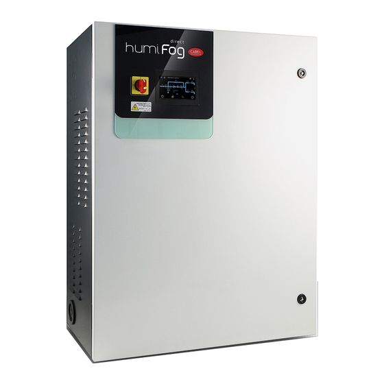
1.6 Main components water inlet 3/4” GAS F power supply 230 V 50 Hz 120 V 60 Hz and return M16x1.5 male water drain 3/4" GAS F Fig. 1.d Cabinet water circuit input / output water Single-blower: M16 x 1.5 male Ref. -
Page 10: Dimensions And Weights
1.7 Dimensions and weights 1.8 Packaging and shipment The cabinet is packaged and delivered on a wooden pallet with a 1.7.1 Dimensions and weights of the cabinet cardboard cover. The user is responsible for moving the cabinet near the point of operation, removing the packaging and placing it in a position ready for the water and electrical connections. -
Page 11: Cabinet Installation
2. CABINET INSTALLATION 2.1.2 Floor-standing installation 2.1 Positioning For floor-standing installation, the unit needs to rest on a raised platform The cabinet, being IP20, must be installed in a closed compartment, so as to allow connection of the drain hose, located on the bottom of the sheltered from the rain, water spray and direct sunlight. -
Page 12: Cabinet Electrical Installation
Blower water supply line 2.3.1 Fuses With reference to the high-pressure hoses provided by CAREL (inside The following table lists the technical specifications of the fuses supplied diameter Ø = 6.3 mm), in order to ensure correct operation of the... -
Page 13: Changing The Oil Cap
The blower units can be mounted either on the wall or on the ceiling. For a correct installation, see the example in Fig. 3.a or contact Carel for ≤ 10°... -
Page 14: Mounting Single Blower Units On The Wall / Ceiling
Fig. 3.b described in paragraph 3.4. Carel also provides an additional kit (including a special plate bent at 90°) First remove the blower unit from the packaging and take off the side for mounting single blower units on the ceiling. -
Page 15: Mounting Double Blower Units On The Ceiling
Also check that the cable is the right size for the distance and voltages Fig. 3.h used. Carel recommends an AWG14 or AWG12 cable, as shown in the technical data at the end of the manual. After installing the blower, make the water connections by connecting... -
Page 16: Electronic Controller Set Up And Connections
4. ELECTRONIC CONTROLLER SET UP AND CONNECTIONS After having correctly installed the cabinet and completed the water and The following types of probes are allowed: • electrical connections, connect the signals used to interface with the 4-20 mA, 0-20 mA current probes •... -
Page 17: Digital Signal From Humidistat Or External Controller
4.4 Analogue signal from an ext. controller The Ethernet port can also be used for the Webserver function (see Chapter 8), so as to monitor and control humiFog Direct via a local As an alternative to the main probe, a signal from an external controller network, without needing a supervisor. -
Page 18: Start-Up And User Interface
5. START-UP AND USER INTERFACE 5.1 Graphic terminal Configuration wizard When starting the first time, a wizard is provided to quickly set the main The 4.3” touch graphic terminal has an interface with coloured and unit parameters. There are at most 10 steps to set up the unit: animated icons. -
Page 19: Touch Display
5.3 Touch display To return to the home menu, press the “HOME” icon HOME menu The “HOME” menu includes information about the pumping station and the zones, including current production, information on the probes and unit status. Fig. 5.f 5.3.3 INPUT/OUTPUT quick menu Press the icon to access the menu. - Page 20 5.3.7 Notification centre Press the icon to access the notification centre. To view the details of an individual notification, press the notification. To return to the previous display, press To return to the home menu, press the “HOME” icon Fig. 5.i 5.3.4 INFO quick menu Press the icon to access the menu.
- Page 21 5.3.11 Main menu 5.3.14 Graphs Press the icon to access the main menu. Press the icon to access the function. The menu provides access to the system items that are available without The graphs function is used to view the values of some system analogue entering a password.
-
Page 22: Remote Installation Of The Touch Display
5.3.15 Functions 5.3.18 Settings Press the icon to access the functions. Press the icon to access the function. The option to select the language following a reboot or unit power on Enter the password (installer password 77) and confirm. can be enabled or disabled. To return to the previous display, press To return to the previous display, press To return to the home menu, press the “HOME”... -
Page 23: Operation Options
6. ADVANCED CONFIGURATION PARAMETERS AND OPERATING OPTIONS 6.1 Main menu and overview of functions When accessing with password 77, the advanced settings button is available for accessing a series of additional submenus. Each submenu is divided into a number of screens identified by the index shown at the top right on the display. The table below provides a complete overview of the screens. -
Page 24: Control
Menu Index Description e. Manual mode De03 Manual management of zone 1 fill valve FV1, zone 1 drain valve DR1, zone 1 fans, set zone 1 production % De04 Manual management of zone 2 fill valve FV2, zone 2 drain valve DR2, zone 2 fans, set zone 2 production % De05 Manual management of unit status contact, alarm relay, cabinet fan, WTS contact f. -
Page 25: Functions
When using a main temperature control probe and an optional limit 6.3 Functions temperature probe, atomisation is related to the temperature reading in 6.3.1 Filling °C or °F made by the probe and increases as the value read deviates from the set point St. -
Page 26: Configurations
6.4 Configurations 6.4.3 External signal setting The type of external signal can be configured on screen index Dc03 for 6.4.1 Main humidity probe setting the single-zone and Dc09 for two-zone cabinets. The main probe can be configured on screen index Dc01 for the single- Index Description Parameter zone and Dc07 for two-zone cabinets. - Page 27 For each probe, after having specified the type, the minimum and maximum values readable can be defined, as well as an “offset” to compensate for any imprecisions in the value read (example: offset = 3% rH corresponds to a 3 percent increase in the humidity value read by the probe).
-
Page 28: Master/Slave Network Of Humidifiers
80 kg/h humiFog direct single-zone unit. Carel markets a switch (P/N: KITSE08000) that can connect a maximum A maximum of 3 Slave units can be connected to a Master, meaning a of eight units (8 Ethernet ports). If necessary, use several KITSE08000 total of 4 humidifiers in the same system. -
Page 29: Master/Slave System Configuration
7.4.1 Maximum Master/Slave system production In the same way as for the individual unit configuration, for the Master/ Slave system the maximum capacity can also be set. To set the maximum capacity, go to menu Dd03. The “Capacity” parameter identifies the maximum production request for the Master/Slave system, and can therefore be set by the user. - Page 30 7.4.4 Display Master/Slave system To display a summary of the Master/Slave system, go to screen Dd08. The menu displays all the units (01, 02, …), the status of each unit and current production as a percentage. The following table lists the Master/ Slave network unit status indications: Symbol Unit status in the Master/Slave system...
-
Page 31: Connectivity
Table 8.a, according to the type Remember that when wanting to connect several devices to the of user. same network, a switch is required (this can be supplied by Carel, P/N KITSE08000). Service... -
Page 32: Supervisor Connection
pGD1 Important: to avoid unwanted modifications, some of the main operating The pGD1 page opens a keyboard for advanced configuration of the unit. and unit parameters can only be set on the web server when the unit is off (off from keypad, settable on the web server). Alarms Display active alarms and alarm log. -
Page 33: List Of Bacnet Parameters
Type Section Address Parameter Variable Size Input registers Inputs Bypass temperature TempByPass 28-32-36-40-44-48-52- 56 Humidity from wireless probe 1 - 8 Inputs_WPrbs.WirelessPrbVal_1 - 8.Hum 30-34-38-42-46-50-54-58 Temperature from wireless probe 1 - 8 Inputs_WPrbs.WirelessPrbVal_1 - 8.Temp Coils Remote control Alarms reset Alarms.AlrmResBySV Unit on/off from supervisor OnOff_Status.SVOn... -
Page 34: Wireless Probes, Installation And Configuration
Wireless probes are available for systems where standard wired probes cannot be used, for example modifications to existing installations. An Access Point (CAREL P/N: WS01AB2M20) is used to connect up to four wireless probes. Recommended Carel wireless probes are the room Key: humiFog Direct humidifier;... -
Page 35: Alarm Table
10. ALARM TABLE The following table shows the alarms that can be displayed, with the corresponding description, causes and possible solutions. Alarm Code Cause Possible solution Reset Alarm relay Action Circuit breaker ABA01 High current due to Check: Manual Active Shutdown overload or short- •... - Page 36 Alarm Code Cause Possible solution Reset Alarm relay Action High fill/wash pressure ABA10 Outlet pressure > 2 Possible blockage of the outlet line. Check: Manual Active Shutdown • correct opening of the NC zone fill solenoid valves (24 Vac bars when filling or when open);...
- Page 37 Alarm Code Cause Possible solution Reset Alarm relay Action Wireless p. 4 offline ALP11 No communication Check: Automatic Active Signal with probe 4 • probe/access point binding • battery charge • probe signal level Wireless p. 5 offline ALP12 No communication Check: Automatic Active...
-
Page 38: Maintenance
11.3 Pump maintenance Generally the oil level should remain constant and periodical top ups should not be needed. If oil leaks are found, contact CAREL. The pump is the most complex mechanical device inside the cabinet, as well as the heart of the high pressure system.It therefore requires regular maintenance, involving the operations described below. -
Page 39: Hour Oil Change Warning
Nonetheless, in specific conditions of stress replacement may be needed earlier. Carel recommends to check the pump operation every 1000 operating hours (signalled by notification). If the pump makes noise, or is not able to reach the required operating pressure (70 bars), the gaskets and valves may need to be replaced sooner. -
Page 40: Cabinet Spare Parts
11 NTC probe for measuring bypass water temperature NTC030WH01 2 N.C. fill solenoid valve ECKFSV0000 12 Mechanical overflow valve, brass Contact CAREL 3 Low pressure gauge, scale 0-12 bars, MCKMA12000 13 Pump drain solenoid valve, 1/8” GAS fitting UAKDRC00003 14 Bypass solenoid valve UAKFL00000 rear fitting 1/4”... -
Page 41: Appendix
12. APPENDIX 12.1 Single-zone cabinet wiring diagram Fig. 12.a "humiFog direct" +0300073EN rel. 1.2 - 02.05.2019... -
Page 42: Two-Zone Cabinet Wiring Diagram
12.2 Two-zone cabinet wiring diagram Fig. 12.b "humiFog direct" +0300073EN rel. 1.2 - 02.05.2019... -
Page 43: Datasheets
12.3 Datasheets 12.3.1 CE version cabinet datasheet PHYSICAL SPECIFICATIONS UA040DD*01 UA080DD*01 Dimensions 630 x 800 x 300 mm 630 x 800 x 300 mm Weight 60 kg (single-zone) 64 kg (single-zone) 64 kg (two zones) 68 kg (two zones) Packaged dimensions 720 x 1020 x 460 mm 720 x 1020 x 460 mm Packaged weight... - Page 44 ELECTRICAL SPECIFICATIONS UA050DU*01 UA090DU*01 Power supply 120 Vac 60 Hz single-phase 120 Vac 60 Hz single-phase Cabinet power cable AWG 14 AWG 12 Power (cabinet only, without blowers) 0.28 kW (single-zone) 0.47 kW (single-zone) 0.38 kW (two zones) 0.57 kW (two zones) Current (cabinet only, without blowers) 5.0 A (single-zone) 8.0 A (single-zone)
- Page 45 12.3.4 UL version blower datasheet Single blower units (for wall-mounting) UL version DLA02UF*00 DLA04UF*00 Dimensions 640 x 200 x 180 mm 940 x 200 x 180 mm Weight 4.5 kg 5.6 kg Packaged dimensions 755 x 235 x 295 mm 1050 x 235 x 295 mm Packaged weight 5.7 kg...
- Page 46 Note "humiFog direct" +0300073EN rel. 1.2 - 02.05.2019...
- Page 48 Agenzia / Agency: CAREL INDUSTRIES - Headquarters Via dell’Industria, 11 - 35020 Brugine - Padova (Italy) Tel. (+39) 049.9716611 - Fax (+39) 049.9716600 e-mail: carel@carel.com - www.carel.com...
Need help?
Do you have a question about the humiFog direct UA040DD101 and is the answer not in the manual?
Questions and answers