Table of Contents
Advertisement
Quick Links
Advertisement
Table of Contents

Related Manuals for Carel humiFog UA1K0HM00


Summary of Contents for Carel humiFog UA1K0HM00
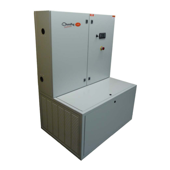
- Page 1 humiFog pressure atomizing 1000-5000 kg/hr READ AND SAVE THESE INSTRUCTIONS...
- Page 2 Open cartons and check for any hidden damage. Mark the shipping waybill accordingly. Check packing slip to ensure all items have been received. Notify CAREL of any shortages or damaged parts. You must notify CAREL within 5 working days of any shortages.
-
Page 3: Table Of Contents
TABLE OF CONTENTS How the humiFog Works .................................. 5 Components ..................................... 6 Main pumping station ................................6 Pumping Station Ratings ................................. 7 Microprocessor control system ............................... 7 Atomizing nozzles ................................... 7 Distribution ....................................8 Models ......................................9 Pumping Station part numbers ..............................9 Pumping Station positioning and mounting............................ -
Page 4: How The Humifog Works
1. How the humiFog Works The humiFog humidification system is a high pressure atomizing system designed to produce a fine mist that readily evaporates to raise the relative humidity. The atomizing humidifier is an efficient humidification system that is especially suitable for larger installations, where high flow-rates of water are required without the necessity of excessive energy expenditure. -
Page 5: Components
2. Components A humiFog system is made up of the following components: One or two pumping stations, each containing an electrical panel and volumetric piston pump. Microprocessor control system. Distribution system with the atomizing nozzles; for ducts/AHUs or rooms. ... -
Page 6: Pumping Station Ratings
* See section 3.1 for complete code structure. Microprocessor control system The humiFog control system is based on the latest, state of the art, CAREL pCO programmable controller. This controller operates a Variable Frequency Drive to modulate water pressure and water flow according to requirements. -
Page 7: Distribution
Distribution The following diagrams illustrate the typical applications in ducts (Fig. 2.b) or directly into ambient locations (Fig. 2.c). The ambient humidity is measured by a probe (1), or receives a command signal from an external controller, and is read by the controller contained in the humiFog pumping station (6). -
Page 8: Models
3. Models Pumping Station part numbers The available humiFog pumping units are coded according to the following structure; Part code: UA ppp X Y 0 x y Where: ppp: rated flow X: modulation control type Y: Power supply x: std or personalization y: pump material Pumping Stations humiFog... -
Page 9: Unit Dimensions And Weights
Unit Dimensions and weights Fig. 4.a 24” (610 mm) UA1K0, UA1K8, & 2K5 UA3K5 & 5K0 24” (610 mm) Weight installed 960 lbs (436 kg) 1000 lbs (455 kg) 32” (812 mm) Weight packaged 1020 lbs (464 kg) 1060 lbs (482 kg) 3”... -
Page 10: Plumbing
5. Plumbing Water supply characteristics The humiFog must be supplied exclusively with treated water according to the listed limit values. Under normal circumstances, this means that the water must be treated with a Reverse Osmosis or Deionizer system. Limit Parameter Symbol Unit of measure Specific conductivity ≅... -
Page 11: Hydraulic Connections
The check valve should be sized to match the flow capacity of the pumping station, thereby ensuring that the pressure provided to the distribution system is maintained. (Check valves are supplied as an option by CAREL.) To facilitate maintenance of the check valves, manual ball valves are recommended as shown. (Fig. 5.a) Fig. -
Page 12: Wiring
Fig. 6.a Disconnect Switch Pumping Station to Multi Zones Pumping stations are wired to the multi-zone control panels by pLAN connections. Please see diagram below, as well as the CAREL pCO platform manual for specific instructions. pLAN CONNECTION WIRING FROM PUMPING STATION, TO ZONE... -
Page 13: Controls Wiring
4. Digital Output "Central Drain" to be used for central drain valves (if applicable). 5. Analog Input "DDC" to be used for direct slave control (if applicable). CENTRAL DRAIN Note; if using CAREL zone control cabinets in a pLan network, this SOLENOID is not used. DIRECT SLAVE + CONTROL (DDC) - Fig. -
Page 14: Start-Up
7. Start-Up IMPORTANT INSTRUCTIONS/WARNINGS: Before connecting the water to the pumping station, flush the supply pipe for around 10 minutes by piping water directly into the drain. Before starting the pumping station, verify that the humidifier is in full operational condition. The hydraulic and electrical equipment should not be locked out. - Page 15 7.2.1 Re-addressing PCO3 controller To change the address of the PCO3 controller, the address of the PGD display must be set to “0” first. (The procedure for setting the address of the PGD back to the proper address is described in 7.2.2.) Unplug J11 connector from PCO3 controller.
-
Page 16: The Humifog Controller
The humiFog controller features a comprehensive, multi-line, information display that shows the operation of the system at a glance. This CAREL pGD user interface is also used for entering values into the controller for applicable settings (i.e. pressure settings, or other set-points). -
Page 17: Keypad
Keypad Button Function Turns off the buzzer (if applicable) and displays the first alarm screen in the alarm-loop. A red LED Alarm located under the Alarm button will be energized when there are alarms present. Return to the “Main” screen From the “Main”... -
Page 18: System Status
System Status On initial power up, the controller will go through a series of self-tests and then activate the program, bringing up the following series of screens. The visibility of some screens is dependent on the configuration of the system. 1 Initial Power Up 2 (Main Screen) 2 (Duplex Main Screen) - Page 19 On/Off Unit 1. On/Off Unit Setpoint 1. Pump Setpoints Clock/Scheduler 1 Clock Input/Output 1. Digital Inputs 2. Relay Outputs 3. Analog Inputs 4. Analog Outputs Data Logger 1. Alarm History Board Switch 1. Board Switch 20 of 55...
- Page 20 Service A. Change Language B. Information D. Working Hours E. BMS config F. Service Settings A. Working hour set 21 of 55...
- Page 21 Service (Con.) F. Service Settings B. Probe adjustment C. Regulation D. User DEV/Change G. Manual management 22 of 55...
- Page 22 Manufacturer a. Configuration The minimum demand to enable pump should be kept at 15%. If adjusted below 15% the maintenance intervals may have to be increased due to the decreased Notes for Duplex: speed of the pump. Pump1 (lead pump) has a lower “Demand to enable”...
-
Page 23: On/Off
Manufacturer (Con.) c. Factory Settings e. Initialization On/Off 1 (On/Off) Shows the unit address of the PCO3 controller. Shows the current actual state. Able to turn the unit enable On/Off 24 of 55... -
Page 24: Setpoint
Setpoint Used for entering pressure setpoint, and deadband. Default pressure is 1,000psi (~70 bar) Clock/Scheduler Used for setting the day, date, and time. Input/Output The Input/Output menu is for reading the current status of the various inputs and outputs on the pumping station. Current status of the Digital inputs. -
Page 25: Board Switch
8.11 Board Switch Used for accessing other controller displays on the network. Changing the address of the unit, allows this interface to access a unit at a different location. 8.12 Service (Initial password is 0000) Service Menu a. Change Language The choices are accessed by using Then press ENTER to make your selection b. - Page 26 e. BMS Config - 1 Used for setting up the communication network. Options: LonWorks, Winload, Modbus, Kyocera, BACNet Note: Some communication protocols will require additional software and hardware. 8.12.1 Service Settings a. Working hour set - 1 a. Working hour set - 2 Used for reading the run hours of the pump, Used for resetting the “Run”...
-
Page 27: Manufacturer
8.12.2 Manual Management g. Manual management - 1 Used for manually operating the pumping station. Note: When in manual control of the pump, make sure there is at least (1) open manifold or circuit for water distribution, otherwise the pump can be damaged by overheating. -
Page 28: Control Method
8.13.3 Factory Settings c. Factory Settings - 1 Used for enabling the unit On/Off by digital Used for setting the pump pressure Used for setting the water conductivity input or by supervisor system. setpoints for warning and blocking alarms. sensor alarm. Used for enabling/disabling the sensor fail Used for setting the high pressure alarm Used for setting the low pressure alarm... -
Page 29: Control For Duplex Operation
When the pumping station is in alarm mode, a NO contact will close to notify the BAS. Control for Duplex Operation The duplex control software is enabled whenever 2 pumps have been addressed to 16 and 17 on the pLAN network. The pump with address 16 defaults to the lead pump, which is called “Pump 1.”... -
Page 30: Trouble-Shooting
Trouble-Shooting The identification and solution of the problem may vary depending on the version of the software: Section 8.12 “Service ” explains how to display the version of the software. PROBLEM POSSIBLE CAUSES CHECKING PROCEDURE SOLUTION No power supply (controller Incorrect power supply or fuses Use a voltage tester and check the power Correct power supply. -
Page 31: Maintenance
Maintenance 11.1 Periodic checks/replacement Maintenance type After the first 50 hours Monthly Every 1000 hours(1) Every 1500/2000 hours(1) Pump: Initial oil change Check accumulator pressure Water filters Check oil level Change oil Low/high pressure seals Valves Rack and room distribution system: Nozzles blocked Check for water leaks Solenoid valve... -
Page 32: Preventive Maintenance Of The Pump: Checking The Oil Level
2. Identify the spare part code in the spare parts list from the reference number. Contact your nearest CAREL representative for any components not listed in the following sections. NOTE: For clarity purposes, only parts of the assembly are shown in the figures below. - Page 33 11.4.1 Replacement parts for the hydraulics and drive assembly Fig. 11.a 34 of 55...
- Page 34 Replacement parts for the electrical panel Fig. 11.b 35 of 55...
-
Page 35: Replacement Parts List
CONTACT CAREL TEMPERATURE SWITCH CONTACT CAREL Tab 11.d See 11.5.7 table for pump part numbers or contact CAREL for additional information. When servicing the belt, be certain that The pulleys are aligned to within 2 and no greater than 1/8” offset ... - Page 36 CONTACT CAREL SECONDARY TRANSFORMER 100VA 240/480V PRIMARY 24V CONTACT CAREL SECONDARY CABINET COOLING FAN 1312545AXX Tab 11.e Part numbers shown are standard for a UA5K0HM002, contact CAREL for other models. 11.5.3 Replacement fuse list PUMP FUSE QUANTITY MODEL LOCATION REQUIRED...
- Page 37 11.5.4 Pump spare parts FOR PUMPING STATIONS: UA1K0H*000 (* for voltage) 66 SERIES, TSF-BRASS 38 of 55...
- Page 38 FOR PUMPING STATIONS: UA1K8H*000 & UA2K5H*000 (* for voltage) 66 SERIES, TSF-BRASS 39 of 55...
- Page 39 FOR PUMPING STATIONS: UA1K0H*001, UA1K8H*001, UA2K5H*001 (* for voltage) 66 SERIES, TSF-SS 40 of 55...
- Page 40 FOR PUMPING STATIONS: UA3K5H*000 & UA5K0H*000 (* for voltage) Emperor, HT Brass 41 of 55...
- Page 41 FOR PUMPING STATIONS: UA3K5H*001 & UA5K0H*001 (* for voltage) KEZ36A PARTS LIST 42 of 55...
- Page 42 11.5.5 Pump replacement kits CODE DESCRIPTION UA1K0H*000 UA1K0H*001 UA1K8H*000 UA1K8H*001 UA2K5H*000 UA2K5H*001 KIT 2 RINGS RADIAL BETWEEN 1309774AXX HEAD AND CARTER 90164800 RADIAL RING SIDE 1309724AXX DRIVE SHAFT 66040009 PISTON D.20 FOR 1309778AXX PUMPS W2025 AND SSE1525 66040409 PISTON D.24 FOR 1309779AXX PUMPS W2421 AND SSE1421 KIT 169 SUC./DISCH.
- Page 43 11.5.7 Pump Cross reference list UA MODEL CAREL CODE MANUFACTURER SERIES MODEL UA1K0HK/M/N000 1309410AXX GENERAL PUMP TSF2019 UA1K8HK/M/N000 UA2K5HK/M/N000 1309411AXX GENERAL PUMP TSF2421 UA3K5HK/M/N000 UA5K0HK/M/N000 1309412AXX GENERAL PUMP 70.HT HTCK3623S UA1K0HK/M/N001 1309413AXX GENERAL PUMP 66.SS TSF2019SS UA1K8HK/M/N001 UA2K5HK/M/N001 1309414AXX GENERAL PUMP 66.SS...
-
Page 44: Wiring Schematic
11.6 Wiring Schematic Figure 11.c 45 of 55... -
Page 45: Communication Points List
Communication Points List Analog variables BMS Address Description Read/Write Variable name humidity sensor or ddc signal for zone 1 zone_signal_1 humidity sensor or ddc signal for zone 2 zone_signal_2 humidity sensor or ddc signal for zone 3 zone_signal_3 humidity sensor or ddc signal for zone 4 zone_signal_4 humidity sensor or ddc signal for zone 5 zone_signal_5... - Page 46 BMS Address Description Read/Write Variable name pump run hours (x1000) runH_pump total capacity of zone 7 total_cap7 total capacity of zone 8 total_cap8 total capacity of zone 9 total_cap9 total capacity of zone 10 total_cap10 total capacity of zone 11 total_cap11 total capacity of zone 12 total_cap12...
- Page 47 Digital variables BMS Address Description Read/Write Variable name humidity sensor failure in zone 1 hum_sensor_fail_1 drain status drain bms on/off of the pump Superv_OnOff supply water valve status WATER_ON Global (general) alarm GLOBAL_ALARM high limit sensor failure alarm 1 hlimit_sensor_fail_1 airflow loss zone 1 airflow_al_1 high humidity in zone 1...
- Page 48 BMS Address Description Read/Write Variable name high humidity in zone 3 hi_hum_al_3 low humidity in zone 2 lo_hum_al_3 stage1 of zone3 exceeded hours run_hour_al_stg1_z3 stage3 of zone3 exceeded hours run_hour_al_stg3_z3 stage4 of zone3 exceeded hours run_hour_al_stg4_z3 stage5 of zone3 exceeded hours run_hour_al_stg5_z3 stage6 of zone3 exceeded hours run_hour_al_stg6_z3...
- Page 49 BMS Address Description Read/Write Variable name stage1 of zone7 exceeded hours run_hour_al_stg1_z7 stage2 of zone7 exceeded hours run_hour_al_stg2_z7 stage3 of zone7 exceeded hours run_hour_al_stg3_z7 stage4 of zone7 exceeded hours run_hour_al_stg4_z7 stage5 of zone7 exceeded hours run_hour_al_stg5_z7 stage6 of zone7 exceeded hours run_hour_al_stg6_z7 humidity sensor failure in zone 8 hum_sensor_fail_8...
- Page 50 BMS Address Description Read/Write Variable name stage2 of zone11 exceeded hours run_hour_al_stg2_z11 stage3 of zone11 exceeded hours run_hour_al_stg3_z11 stage4 of zone11 exceeded hours run_hour_al_stg4_z11 stage5 of zone11 exceeded hours run_hour_al_stg5_z11 stage6 of zone11 exceeded hours run_hour_al_stg6_z11 humidity sensor failure in zone 12 hum_sensor_fail_12 high limit sensor failure alarm 12 hlimit_sensor_fail_12...
-
Page 51: Warranty
90 days, whichever is longer, so long as the product has been installed and operated in accordance with all appropriate manuals and wiring diagrams, and started up by a qualified CAREL USA technician. Any product or part that is found to be defective will, at the option of CAREL USA, LLC be replaced or repaired. - Page 52 NOTES 53 of 55...
- Page 53 NOTES 54 of 55...
- Page 54 55 of 55...
Need help?
Do you have a question about the humiFog UA1K0HM00 and is the answer not in the manual?
Questions and answers