
Related Manuals for Carel humiFog direct


Summary of Contents for Carel humiFog direct
- Page 1 User manual NO POWER & SIGNAL CABLES TOGETHER READ CAREFULLY IN THE TEXT!
-
Page 3: Table Of Contents
6.8 Unit status digital output ................17 6.9 Production percentage analogue outputs ..........17 START-UP AND USER INTERFACE 7.1 Graphic terminal ................... 18 7.2 Start-up ......................18 7.3 Touch display ....................19 7.4 Remote installation of the touch display ..........22 "humiFog direct" +0300073EN rel. 1.4 - 29.03.2022... - Page 4 "humiFog direct" +0300073EN rel. 1.4 - 29.03.2022...
-
Page 5: Introduction
The liability of CAREL in relation to its products is specifi ed possible way for the specifi c application. -
Page 6: Safety Instructions
The appliance must not be operated with a DC power supply. Regularly check that all safety and monitoring devices are working properly. Do not remove or disable the safety devices. NOTICE: Possibility of water leaks due to faulty connections or malfunctions. "humiFog direct" +0300073EN rel. 1.4 - 29.03.2022... -
Page 7: General Description
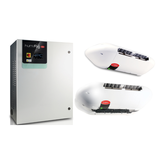
Power supply (230V 50 Hz or 120V 60 Hz) Expansion vessel Electrical connection from cabinet to the blowers humiFog Direct cabinet Mechanical feedwater fi lter High pressure water hoses (70 bars) Check valve humiFog Direct blower units "humiFog direct" +0300073EN rel. 1.4 - 29.03.2022... -
Page 8: Cabinet Part Numbers
DLA04UF100 Front blower 11.0 l/h (4 x 2.8 l/h nozzles) 120 V 60 Hz Carel in diff erent lengths. The part numbers available are listed below. DLA04UF200 Front blower 16.0 l/h (4 x nozzles from 4.0l/h) 120 V 60 Hz All the hoses have with M16x1.5 female couplings with O-rings, ideal for... -
Page 9: Structure
Controller Fig. 3.e Expansion card Transformer Ref. Description metal support / wall bracket Cooling fan side plastic cover centre plastic cover pressurised water manifold nozzle power LED terminal block for blower power supply "humiFog direct" +0300073EN rel. 1.4 - 29.03.2022... -
Page 10: Dimensions And Weights
15.5 kg (2007). Double blower, 4 modules (37 x 8 x 16 inches) (34 lb) The unit is UL marked in the 120 Vac 60 Hz version in accordance with Tab. 3.g directive UL998. "humiFog direct" +0300073EN rel. 1.4 - 29.03.2022... -
Page 11: Cabinet Installation
Should on the other hand the humidifi er be fed with treated water from a Carel reverse osmosis system connected to potable water, the dual check Fig. 4.b valve shall be installed in the supply line to the reverse osmosis system. -
Page 12: Electrical Installation
The use of demineralised water is also required to comply with standards UNI8883, VDI6022 and VDI3803. humiFog Direct must only operate on demineralised water that falls within the limits listed in the following table. Normally, these values can Fig. 4.f be obtained by reverse osmosis or nanofi ltration of the feedwater. -
Page 13: Changing The Oil Cap
The blower units can be mounted either on the wall or on the ceiling. rH = 40% T = 25 °C For a correct installation, see the example or contact Carel for diff erent Fig. 5.a temperature and humidity conditions. -
Page 14: Mounting Single Blower Units On The Wall / Ceiling
"Blower unit electrical connection". support the weight of the blower unit (concrete, not plasterboard). Carel also provides an additional kit (including a special plate bent at 90°) for mounting single blower units on the ceiling. Fig. 5.b First remove the blower unit from the packaging and take off the side plastic covers. -
Page 15: Blower Unit Electrical Connection
Fig. 5.h Also check that the cable is the right size for the distance and voltages used. Carel recommends an AWG14 or AWG12 cable, as shown in the technical data at the end of the manual. After installing the blower, make the water connections by connecting... -
Page 16: Electronic Controller Set Up And Connections
Direct humidifi er to the c.pHC electronic controller (and the The following types of probes are allowed: c.pCO controller on two-zone cabinets. -
Page 17: Analogue Signal From An Ext. Controller
As an alternative to the main probe, a signal from an external controller network, without needing a supervisor. can be used. The latter processes the request to send to humiFog Direct via an analogue signal, which varies from 0 to 100%. humiFog will adjust 6.7 Alarm relay output... -
Page 18: Start-Up And User Interface
Main temperature probe + temperature limit probe; • Main humidity probe + temperature limit probe; The display shows the “humiFog Direct” logo, after which the menu • Main temperature probe + humidity limit probe; language can be chosen, from the following options: •... -
Page 19: Touch Display
The wizard is now fi nished: you can choose whether or not to display it Limit probe set point 0-100% rH 0-40 °C 80% rH 15 °C the next time humiFog direct is powered on. In any case, the wizard is Limit probe band 0-10% rH 0-10 °C 5% rH 2 °C... - Page 20 The page displayed shows some of the characteristics of the individual unit and the system. Fig. 7.k Fig. 7.n To quickly display the IP addresses of the units making up the Main/ Secondary network, press "humiFog direct" +0300073EN rel. 1.4 - 29.03.2022...
- Page 21 To return to the previous display, press Moving to the right again, the history of the system's digital variables is To return to the home menu, press the “HOME” icon displayed on the third screen. Fig. 7.q Fig. 7.t "humiFog direct" +0300073EN rel. 1.4 - 29.03.2022...
-
Page 22: Remote Installation Of The Touch Display
HCTXDA0000. The kit comprises a touch display, a 24 Vdc power supply, a telephone cable and a telephone splitter for simultaneous connection of the two displays (one in the remote position and the other installed on Fig. 7.x the humidifi er). "humiFog direct" +0300073EN rel. 1.4 - 29.03.2022... -
Page 23: Advanced Configuration Parameters And Operating Options
Setting the screen language Df03 Change menu access password Df04 Setting the international/imperial measuring system Df05 Setting the machine model Df06 Restore factory values Df07 Enabling of USB port reading for unit software updating "humiFog direct" +0300073EN rel. 1.4 - 29.03.2022... -
Page 24: Control
If using wireless probes (maximum of four), two groups of probes can be defi ned: the group of main probes and the group of limit probes. In this case, the "humiFog direct" +0300073EN rel. 1.4 - 29.03.2022... -
Page 25: Functions
If a fault is detected for longer than the value of the "Delay" is detected as beeing empty parameter (seconds), the "main probe broken or disconnected" alarm will Tab. 8.c be activated. "humiFog direct" +0300073EN rel. 1.4 - 29.03.2022... - Page 26 If a fault is detected for longer than the value of the "Delay" parameter (seconds), the "main probe broken or disconnected" alarm will be activated. "humiFog direct" +0300073EN rel. 1.4 - 29.03.2022...
-
Page 27: Main/Secondary Network Of Humidifiers
160 kg/h, a Main/Secondary system Carel markets a switch (P/N: KITSE08000) that can connect a maximum can be created with two 80 kg/h humiFog direct single-zone unit. of eight units (8 Ethernet ports). If necessary, use several KITSE08000 A maximum of 3 Secondary units can be connected to a Main, meaning switches with a cascaded arrangement. -
Page 28: Main/Secondary System Confi Guration
Note: it may take a few seconds (max 10 s) for the Main to start sending the production request to the Secondary/Secondarys. This is also true when, automatically, the Main unit is changed (for example, in the event of malfunctions). "humiFog direct" +0300073EN rel. 1.4 - 29.03.2022... - Page 29 Note: if a unit goes offl ine due to a malfunction or shutdown, it will temporarily be excluded from the system, and when next restarted it may take 15 seconds or more to automatically come online status again. "humiFog direct" +0300073EN rel. 1.4 - 29.03.2022...
-
Page 30: Connectivity
Remember that when wanting to connect several devices to the Tab. 10.a same network, a switch is required (this can be supplied by Carel, P/N KITSE08000). The IP address of the humiFog Direct unit is shown on the display, under: • D. Settings •... -
Page 31: Supervisor Connection
[°C]/[°F] 28-32-36- Humidity from wireless probe 1 ÷ 8 Inputs_WPrbs.Wire- [°C]/[°F] registers 40-44-48- lessPrbVal_1 ÷ 8.Hum 52- 56 30-34-38- Temperature from wireless probe 1 ÷ 8 Inputs_WPrbs.Wire- [%rh] 42-46-50- lessPrbVal_1 ÷ 8.Temp 54-58 "humiFog direct" +0300073EN rel. 1.4 - 29.03.2022... -
Page 32: List Of Bacnet Parameters
Setpoint limit zone 1 (temperature) RegCfg_1.SetPLim_temp [°C]/[°F] Setpoint zone 2 (humidity) RegCfg_2.SetP_hum Setpoint zone 2 (temperature) RegCfg_2.SetP_temp [°C]/[°F] Setpoint limit zone 2 (humidity) RegCfg_2.SetPLim_hum Setpoint limit zone 2 (temperature) RegCfg_2.SetPLim_temp [°C]/[°F] Tab. 10.c "humiFog direct" +0300073EN rel. 1.4 - 29.03.2022... -
Page 33: Wireless Probes, Installation And Configuration
Wireless probes are available for systems where standard wired probes cannot be used, for example modifi cations to existing installations. An Access Point (CAREL P/N: WS01AB2M20) is used to connect up to four wireless probes. Recommended Carel wireless probes are the room Key: humiFog Direct humidifi er;... -
Page 34: Alarm
(The 0.3 bar • that the alarm of the reverse osmosis system upstream unit periodically of humiFog direct is not going off performs up to • that there is an expansion tank or storage tank with 30 automatic booster pump properly calibrated upstream of the restart attempts) humiFog direct. - Page 35 • the signal level of the probe Wireless probe 4 offl ine ALP11 No communication Verify: Automatic Active Signal with probe 4 • the probe/access point association • battery status • the signal level of the probe "humiFog direct" +0300073EN rel. 1.4 - 29.03.2022...
- Page 36 DR1 and DR2 discharge solenoid valves. Verify that the pump is capable of delivering the required fl ow rate to meet the nozzle load. Tab. 12.a "humiFog direct" +0300073EN rel. 1.4 - 29.03.2022...
-
Page 37: Maintenance
If it is necessary to shut down the system for Humidity probe function test Restoration more than 48 hours by disconnecting the power supply, the procedure and limit probe intervention test described in the section "Shutting down the system"... -
Page 38: Special Maintenance
(oil P/N 5024646AXX). check oil level Generally the oil level should remain constant and periodical top ups check/change oil should not be needed. If oil leaks are found, contact CAREL. check/replace gaskets and valves Tab. 13.a 13.4.1 Oil change Important: after the fi rst 50 hours of operation, the oil in the pump needs to be changed (P/N 5024646AXX). -
Page 39: Hour Oil Change Warning
The same occurs after 2000 hours of operation. 4 nozzle water manifold, single blower Contact CAREL After 3000 hours of operation, instead, humiFog direct generates a non- 4 nozzle water manifold, double blower Contact CAREL 8 nozzle water manifold, double blower Contact CAREL blocking "request for oil change and parts replacement"... -
Page 40: Spare Parts
6 40-50 l/h pump kit, brass UAKP040M00 23 Pump motor cooling fan 1312545AXX 80-90 l/h pump kit, brass UAKP080M00 Tab. 13.c Valve and gasket kit for pump (for all humiFog Direct UAKVGO1501 models) Replacement oil 5024646AXX 7 High pressure gauge, scale 0-100 bars, UAKMWHP001 radial fi tting 1/4”... -
Page 41: Appendix
14. APPENDIX 14.1 Single-zone wiring diagram Fig. 14.a "humiFog direct" +0300073EN rel. 1.4 - 29.03.2022... -
Page 42: Two-Zone Wiring Diagram
14.2 Two-zone wiring diagram Fig. 14.b "humiFog direct" +0300073EN rel. 1.4 - 29.03.2022... -
Page 43: Datasheets
72 kg (two zones) Delivery and storage temperature and humidity -10/50°C 0-90% rH -10/50°C 0-90% rH Operating temperature and humidity 2/40°C 5-95% rH 2/40°C 5-95% rH IP rating IP20 IP20 Conformity UL998 UL998 Tab. 14.e "humiFog direct" +0300073EN rel. 1.4 - 29.03.2022... - Page 44 230 Vac 50 Hz 230 Vac 50 Hz Fan total air fl ow-rate 600 m3/h 1,200 m3/h Blower connection cable AWG 14 AWG 14 Maximum number of blower units (connected to one cabinet) Tab. 14.j "humiFog direct" +0300073EN rel. 1.4 - 29.03.2022...
- Page 45 720 m3/h 1,440 m3/h Blower connection cable AWG 14 with UA050% AWG 14 with UA050% AWG 12 with UA090% AWG 12 with UA090% Maximum number of blower units (connected to one cabinet) Tab. 14.l "humiFog direct" +0300073EN rel. 1.4 - 29.03.2022...
- Page 48 Agenzia / Agency: CAREL INDUSTRIES - Headquarters Via dell’Industria, 11 - 35020 Brugine - Padova (Italy) Tel. (+39) 049.9716611 - Fax (+39) 049.9716600 e-mail: carel@carel.com - www.carel.com...
Need help?
Do you have a question about the humiFog direct and is the answer not in the manual?
Questions and answers