
Subscribe to Our Youtube Channel
Summary of Contents for Agena BIOSCIENCE MassARRAY Nanodispenser RS1000
- Page 1 MassARRAY ® Nanodispenser RS1000 USER GUIDE v2.1 For Research Use Only. Not for Use in Diagnostic Procedures.
- Page 2 Agena Bioscience. Printed in the United States of America.
-
Page 3: Table Of Contents
Safety......14 Contacting Agena Bioscience .... -
Page 4: Table Of Contents
Appendix A Changing the Pin Format....117 Adapting an instrument to 6-pin or 1-pin format ..Appendix B Manually Adjusting Dispense Speed . -
Page 5: Chapter 1 Introduction
Contacting Agena Bioscience ........ -
Page 6: Instrument Description
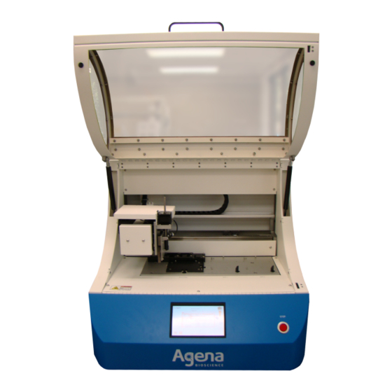
6. Start the dispensing run. 7. Clear the instrument deck when the run is finished. 1.2 Instrument Description MassARRAY The MassARRAY Nanodispenser RS1000 is a self-contained, enclosed instrument that Nanodispenser RS1000 uses computer-controlled robotics to dispense nanoliter volumes of fluid from microtiter instrument versions plates onto SpectroCHIP Arrays. - Page 7 Chapter 1 Introduction Description of Changes Deck Plate Left Side Panel Front Panel Deck plate modified to accept plate flatteners instead of microtiter plate (MTP) clips and spacer blocks to enable 384-96 compatibility. The Nanodispenser RS1000 has a factory-installed pin array format that can be adapted to a different dispensing format using an optional adapter kit (Table 1.3).
- Page 8 Chapter 1 Introduction Figure 1.2 Instrument Front Touchscreen Controls the Stop Button instrument Immediately stops motion Figure 1.3 Instrument Back: Power Switch and Ports For more information about these ports, see External ports, page 12. I/O Port: Future expansion USB 2.0 Ports (2): Data transfer, keyboard, or mouse VGA Port: External display Ethernet Port: Sample tracking, data...
- Page 9 Chapter 1 Introduction Figure 1.4 Instrument Left Side With 3 Ports Vac Waste Port Vacuum tank drains through this port. Waste Port Supply Port Waste tank drains Supply tank is filled through this port; through this port. can also be used to connect external supply tank.
- Page 10 Chapter 1 Introduction Figure 1.6 Overhead View of instrument X-Axis Transport Allows side-to-side movement of pin array assembly. Pin Array Assembly Contains the pin array used to load and dispense liquid; allows up-and-down movement. Y-Axis Transport Allows front to back movement of pin array assembly.
- Page 11 Chapter 1 Introduction Main door and front access panel CAUTION Opening the main door disengages the safety interlock and aborts the dispensing run in progress. page 15 for more details on the enclosure safety interlocks. Opening or closing the main door To open the main door, lift the door fully open using the handle (Figure 1.8).
- Page 12 Chapter 1 Introduction Figure 1.9 Safety Interlock Disengaged Message Opening or closing the front access panel The front access panel enables access to the valves that control filling the supply tanks and emptying the waste tanks. CAUTION Opening the front access panel disengages the safety interlock and aborts a dispensing run in progress.
- Page 13 Chapter 1 Introduction Figure 1.10 Opening the Front Access Panel Front access panel To close the front access panel: Grasp the sides of the front access panel. There are two brackets, one under each side of the panel that hold it open. Simultaneously lift up on the access panel lightly and press the brackets up to disengage them from the locked position.
- Page 14 The Ethernet port should be used to connect the instrument to a network solely for transmitting sample-tracking and processing data, and for remote servicing by Agena Bioscience Customer Support. The Ethernet port should not be used for general networking. The I/O port is not currently used. It is reserved for future expansion.
-
Page 15: Required And Recommended Equipment And Consumables
Chapter 1 Introduction 1.3 Required and Recommended Equipment and Consumables Table 1.8 Required Consumables Item Specifications 384 or 96 SpectroCHIP Arrays Included with Agena Bioscience SpectroCHIP Array and Clean Resin Kits Clean Resin Included with Agena Bioscience SpectroCHIP Array and Clean... -
Page 16: Safety
WARNING! A warning describes a situation that could cause personal injury, damage to the instrument, or pose environmental concerns. WARNING WARNING! Use the Nanodispenser RS1000 as specified by Agena Bioscience in this manual and other supporting documents. Any other use may impair the protections provided by the instrument. - Page 17 Chapter 1 Introduction Figure 1.11 Enclosure Safety Interlocks Main door interlock Front panel interlock Stop button Enclosure safety The instrument has a safety interlock system that prevents it from operating if the: interlocks • Stop button is pressed • Main door is open •...
- Page 18 Chapter 1 Introduction Figure 1.12 Safety Interlock Message To resume operating the instrument: Press the Stop button again so it returns to its original position (flush with the instrument surface). Close the main door. Close the front access panel. Touch HOME in the safety interlock message.
-
Page 19: Contacting Agena Bioscience
(Figure 1.13). Figure 1.13 Safe Lifting Points on the Nanodispenser RS1000 1.5 Contacting Agena Bioscience Please contact your local Agena Bioscience office for customer support. CORPORATE HEADQUARTERS & NORTH AMERICA Agena Bioscience, Inc. 4755 Eastgate Mall San Diego, CA 92121... - Page 20 Bowen Hills, QLD 4006 Australia Phone: (+61) 7 3088 1600 Fax: (+61) 7 3088 1614 Email: support-asia@AgenaBio.com CHINA Agena Bioscience (Shanghai) Co., Ltd. Room 1609-1613, Building A Fenglin International Center No. 380 Fenglin Road Xuhui District Shanghai 200032 PR China...
-
Page 21: Chapter 2 Dispensing To Spectrochip Arrays
Chapter 2 Dispensing to SpectroCHIP Arrays Dispensing Overview ............19 Desalting the Analyte . - Page 22 Chapter 2 Dispensing to SpectroCHIP Arrays Step See Page • Empty the calibrant reservoir. 9. Log off and turn off the Nanodispenser RS1000. This chapter explains how to desalt the analyte with resin, and then dispense analyte and calibrant to SpectroCHIP Arrays. Table 2.1 lists the workflow steps.
-
Page 23: Desalting The Analyte
Chapter 2 Dispensing to SpectroCHIP Arrays 2.2 Desalting the Analyte IMPORTANT Make sure the assay protocol has been completed, as per the appropriate panel user guide, including the final water addition step (for iPLEX and MassCLEAVE panels only). Use the desalting method appropriate to the panel chemistry (dry resin method for iPLEX and MassCLEAVE, wet rein method for UltraSEEK). -
Page 24: Instrument Start Up And Shut Down
Chapter 2 Dispensing to SpectroCHIP Arrays Seal the reaction plate and centrifuge for 5 minutes at 1000 x g to make sure resin settles at the bottom of the wells. Rotate the reaction plate for at least 15 minutes, at 24 RPMs. The rotator must rotate the microplate in a fashion that inverts the sample. - Page 25 Chapter 2 Dispensing to SpectroCHIP Arrays NOTE NOTE If a user name and password has not yet been assigned, use the pre-installed user name "researcher" and password "researcher". Note that user names and passwords are case sensitive. page 26 for more details on creating user names and passwords. Tap the type your name box on the Login screen.
- Page 26 Chapter 2 Dispensing to SpectroCHIP Arrays Tap LOG OFF on the main menu. The Login screen appears. NOTE NOTE Tap BACK on any screen to return to the main menu. Logging off does not shut down the instrument. See Shutting down the instrument, page 24 for details on instrument shut down.
- Page 27 Chapter 2 Dispensing to SpectroCHIP Arrays Figure 2.6 Prompt to Save the Configuration File YES Saves the current instrument configuration to the DispenseCONFIG.xml file. The parameters in the configuration file are applied at the next instrument startup. It is usually recommended that you save the configuration file so that the instrument uses the last configuration parameters.
- Page 28 Table 2.2 User Levels Pre-installed Login Name/ Level Name Description Password Engineer Used by a Agena Bioscience engineer/determined at install by representative for installation and Agena Bioscience Customer configuration of the instrument. Engineer Support. level can access all operating and configuration functions.
- Page 29 Chapter 2 Dispensing to SpectroCHIP Arrays Log in as administrator. The pre-installed administrator login name and password are given during training. page 22 for details on how to log on to the instrument. NOTE NOTE If necessary, log off the previous user by tapping LOG OFF on the main menu.
-
Page 30: Pre-Run Checks
Chapter 2 Dispensing to SpectroCHIP Arrays To delete a user: a. Tap the user name to be deleted (Figure 2.9). b. Tap the DEL USER button in the User Setup screen. c. Tap YES in the confirmation message that appears. Figure 2.9 Select and Confirm the User to be Deleted To edit user login information (for example, change the password or user level): a. - Page 31 Chapter 2 Dispensing to SpectroCHIP Arrays To check tank status: Tap the STATUS button on the Main Menu (or any other screen). Figure 2.10 STATUS Button in the Main Menu On the Machine Status screen that appears, tap the Page 2 tab (bottom of the screen).
-
Page 32: Setting Up The Dispensing Run
Chapter 2 Dispensing to SpectroCHIP Arrays To prime the pins: Go to the Maintenance screen (tap the Back button on any screen and tap the MAINTENANCE button on the Main Menu). Tap the COMPLETE CYCLE button (Figure 2.12). Figure 2.12 Maintenance Screen Select 5-10 complete cycles in the wash cycles screen that appears and tap OK (Figure 2.13). - Page 33 Chapter 2 Dispensing to SpectroCHIP Arrays Recommended dispense settings Table 2.3 Recommended Dispense Settings Recommended Setting Description Range Value Target Volume Target amount of analyte to be dispensed onto each pad. iPLEX: 12 nL MassCLEAVE: 12 nL UltraSEEK: 25 nL Volume Check The range of dispensed analyte that is acceptable MassCLEAVE and...
- Page 34 Chapter 2 Dispensing to SpectroCHIP Arrays Loading a method A method file specifies dispensing run settings, such as the mapping file, pin cleaning operations to perform, and speed at which the pin array moves. The instrument includes predefined method files for some common types of dispensing. You can also create custom method files.
- Page 35 Chapter 2 Dispensing to SpectroCHIP Arrays The method files included in the list depend on the pin array format. For example, only 6-pin method files will be available for an instrument with a 6-pin array. Tap open to load the file. The Method screen appears and displays the selected method (Figure 2.16).
- Page 36 Chapter 2 Dispensing to SpectroCHIP Arrays Selecting setup Tap the setup tab on the Method screen. parameters Specify the SpectroCHIP Array positions The instrument deck accepts a standard SCOUT plate which holds the SpectroCHIP Arrays that will receive analyte and/or calibrant. The standard SCOUT plate has ten SpectroCHIP Array positions (Figure 2.17).
- Page 37 Chapter 2 Dispensing to SpectroCHIP Arrays Enable sample tracking When sample tracking is enabled, the microtiter plate and SpectroCHIP Array barcodes are scanned and information about how the sample plate wells are mapped to the SpectroCHIP Array pads is sent to the database (MassARRAY Transfer Server; see Figure 2.19).
- Page 38 Chapter 2 Dispensing to SpectroCHIP Arrays Ensure that the Enable box under Auto Tuning is checked (see Figure 2.21). Enter the Target Volume in nL. • For iPLEX and MassCLEAVE analyte, enter 12. • For UltraSEEK analyte, enter 25. Ensure that the Enable box under Volume Check is enabled. Enter an upper and lower limit for dispense volume.
- Page 39 Chapter 2 Dispensing to SpectroCHIP Arrays Selecting cleaning Tap the cleaning tab on the Method screen. Verify that all cleaning steps are check- parameters marked in the Cleaning Setup box (Figure 2.22 Figure 2.22 Cleaning tab Selecting aspirate/ Tap the aspirate/dispense tab on the method screen. dispense parameters To set the dispensing speed: Under dispense settings, tap the dispense speed value...
- Page 40 Chapter 2 Dispensing to SpectroCHIP Arrays Under calibrant, tap the dispense speed value. Enter a dispense speed using the numeric keypad that appears, and tap enter. • For iPLEX and UltraSEEK, enter 100. • For MassCLEAVE, enter 140. Figure 2.24 Set the Calibrant Dispense Speed Tap and enter a dispense speed value.
-
Page 41: Microtiter Plate Checks
Chapter 2 Dispensing to SpectroCHIP Arrays 2.6 Microtiter plate checks Checking the resin and A layer of Clean Resin (yellow or brownish-yellow color) underlies a liquid analyte layer in liquid levels a microtiter plate well. The levels of the resin and liquid must be checked to ensure they are adequate for nanodispensing. - Page 42 Chapter 2 Dispensing to SpectroCHIP Arrays Figure 2.28 Example of a Well With Lower Liquid Level Since this well has less resin, the liquid level above it is lower than in the other wells, even though the volume of liquid may be the same. Bring up the liquid level in "low"...
- Page 43 Chapter 2 Dispensing to SpectroCHIP Arrays NOTE NOTE Since the resin levels may have been adjusted in the preceding procedure (Checking the resin and liquid levels, page 39), it is assumed that the resin in the microtiter plate wells comes up no higher than 4.5-5.0 mm (6 mg resin plates) from the bottom of wells.
- Page 44 Chapter 2 Dispensing to SpectroCHIP Arrays Enter the aspirate offset: a. Tap the aspirate offset value (Figure 2.33). b. In the number pad that appears, enter the aspirate offset value you calculated above and tap enter. Figure 2.33 Enter the Aspirate Offset Return to the Transfer screen: a.
-
Page 45: Setting Up The Instrument Deck
Chapter 2 Dispensing to SpectroCHIP Arrays 2.7 Setting up the instrument deck Filling the calibrant NOTE NOTE reservoir If you are not dispensing calibrant, skip this section and proceed to Loading the microtiter plates, page 44 The calibrant reservoir is a single-well insert located on the dry station. The instrument aspirates calibrant from this reservoir. - Page 46 Chapter 2 Dispensing to SpectroCHIP Arrays Loading the microtiter NOTE NOTE plates If only calibrant will be dispensed, it is not necessary to load microtiter plates (calibrant is aspirated from the calibrant reservoir). Skip this section and proceed to Loading the SpectroCHIP Arrays, page 45.
- Page 47 (Figure 2.38). Insert the SpectroCHIP Arrays into the SCOUT plate positions that were specified earlier (see page 34). Orient the SpectroCHIP Arrays so that the Agena Bioscience logo is at the bottom (Figure 2.38). CAUTION Do not touch the SpectroCHIP Array surface. Handle a SpectroCHIP Array only by the edges. It is strongly recommended that you use tweezers to handle the SpectroCHIP Arrays.
-
Page 48: Starting The Dispensing Run
Chapter 2 Dispensing to SpectroCHIP Arrays Place the SCOUT plate back onto the processing deck (Figure 2.37): a. Place the left edge of the SCOUT plate down first, against the alignment post at the left of the SCOUT plate deck position. b. - Page 49 Chapter 2 Dispensing to SpectroCHIP Arrays NOTE NOTE If the currently loaded method is a predefined method, you cannot save changes to it. Predefined method files are read-only. Tapping SAVE in this case does not affect the method file, but will load the changes into instrument memory (same as Apply).
- Page 50 Chapter 2 Dispensing to SpectroCHIP Arrays 2.42). Tap OK and observe the The rinse station preparation screen appears (Figure rinse station as it briefly runs (Figure 2.43). If water flows out of the rinse station chimneys, the rinse station is operating correctly. Figure 2.42 Rinse Station Preparation Screen-1 Figure 2.43 Nanodispenser RS1000 Rinse Station Rinse station...
-
Page 51: Dispensing Run Activities
Chapter 2 Dispensing to SpectroCHIP Arrays Figure 2.44 Rinse Station Preparation Screen-2 Transfer begins after it is confirmed that the rinse station is operating properly. It takes approximately 8-10 minutes to complete dispensing from one 384-well microtiter plate to one 384 SpectroCHIP Array using the standard 24-pin array format or from one 96-well microtiter plate to one 96 SpectroCHIP Array using the 6-pin array format. - Page 52 Chapter 2 Dispensing to SpectroCHIP Arrays Checking the position The position of each SpectroCHIP Array is checked to make sure that each is properly of each SpectroCHIP aligned. The vision system locates the required fiducials (small dots on the SpectroCHIP Array Array surface located between pads which are used for positioning and alignment) and verifies that the SpectroCHIP Array is properly aligned.
- Page 53 Chapter 2 Dispensing to SpectroCHIP Arrays Figure 2.47 Transfer Screen (Transfer Tab) During Dispensing When dispensing begins, microtiter plate (MTP) diagrams appear and are updated to reflect the dispensing progress. Wells in the MTP that have been dispensed to the SpectroCHIP Array are empty (colorless).
- Page 54 Chapter 2 Dispensing to SpectroCHIP Arrays Volume tab The Volume tab (Figure 2.49) shows the dispense volume and a photo of each dispensed pad. Figure 2.49 Transfer Screen (Volume Tab) During Transfer Tuning tab The Tuning tab (Figure 2.50) shows a graph of dispense volume and speed. Figure 2.50 Transfer Screen (Tuning Tab) During Transfer MassARRAY®...
- Page 55 Chapter 2 Dispensing to SpectroCHIP Arrays Vision tab The Vision tab (Figure 2.51) shows a photo of the pads and the dispense volumes for each during dispensing. (It also shows the SpectroCHIP Array alignment and barcode checking prior to dispensing; see page 50.) Figure 2.51 Transfer Screen (Vision Tab) During Transfer...
-
Page 56: Clearing The Instrument Deck
Chapter 2 Dispensing to SpectroCHIP Arrays Figure 2.53 Sample Tracking Message This dialog box appears during data transfer. Text file send status: Text files Archiving – Send in progress. (one per Successfully Archived – File sent successfully to SpectroCHIP Array) the MassARRAY Transfer Server. - Page 57 Chapter 2 Dispensing to SpectroCHIP Arrays The safety interlock is disengaged! message appears. Pull the spring-loaded positioners away from the SCOUT plate and lift it off the deck. If the SpectroCHIP Arrays will be processed immediately, remove the them from the SCOUT plate using tweezers and place them in the SpectroCHIP Array carrier for the Analyzer.
-
Page 58: Accessing Dispense Volume Data From Previous Runs
Chapter 2 Dispensing to SpectroCHIP Arrays Wait for the pin array assembly to move to home position (all the way left, forward, and up). 2.11 Accessing dispense volume data from previous runs On the Main Menu, tap the VOLUME button (Figure 2.56). -
Page 59: Chapter 3 Methods And Mappings
Chapter 3 Methods and Mappings About method files ............57 About mapping files . -
Page 60: About Mapping Files
Chapter 3 Methods and Mappings The Nanodispenser RS1000 has several predefined method files for common types of dispensing (see Table 3.1). You may also create custom method files (see page 63). Table 3.1 Predefined Method Files Required Method File Name Description Pin Format 384 MTP to 384... - Page 61 Chapter 3 Methods and Mappings Table 3.2 Predefined Mapping Files Required Mapping File Name Description Pin Format 384 MTP to 384 One or two 384-well microtiter plates to one or SpectroCHIP Array Map two 384 SpectroCHIP Arrays. 96 MTP to 96 One or two 96-well microtiter plates to one or two SpectroCHIP Array Map 96 SpectroCHIP Arrays.
- Page 62 Chapter 3 Methods and Mappings Figure 3.2 384 MTP to 384 SpectroCHIP Array Mapping MTP 1 MTP 2 384-well microtiter plates 384 SpectroCHIP Arrays SCOUT plate Figure 3.3 shows how the plate wells are mapped to the SpectroCHIP Array pads. The diagrams represent a single plate and SpectroCHIP Array.
- Page 63 Chapter 3 Methods and Mappings Figure 3.3 384 Plate to 384 SpectroCHIP Array Plate-to-SpectroCHIP Array Mapping 384-well microtiter plate 384 SpectroCHIP Array Each cell in this diagram represents a plate well. The 24- Each cell in this diagram represents a SpectroCHIP Array pin array is designed to fit into a 4 X 6 group of pad.
- Page 64 Chapter 3 Methods and Mappings 96 MTP to 96 Use this mapping file to dispense from 96-well plates to 96 SpectroCHIP Arrays. This SpectroCHIP Array mapping file requires the 6-pin format. A maximum of two plates and two SpectroCHIP mapping file Arrays can be run using this mapping file.
-
Page 65: Creating A Custom Method File
Chapter 3 Methods and Mappings Figure 3.5 shows how plate wells and SpectroCHIP Array pads are mapped in the 96 MTP to 96 SpectroCHIP Array mapping file. The diagrams represent a single plate and SpectroCHIP Array. The same mapping scheme is used for each plate and SpectroCHIP Array in the 96 MTP to 96 SpectroCHIP Array method file—MTP 1 is mapped to SpectroCHIP Array 1 and MTP 2 is mapped to SpectroCHIP Array 2. - Page 66 Chapter 3 Methods and Mappings For example, to create a custom method file, the dispensing parameters in an existing method file can be changed, and/or a new mapping file can be included in the existing method file. (Figure 3.6). Figure 3.6 Example of Creating a Custom Method File Modify Method Parameters Customize dispensing parameters...
- Page 67 Chapter 3 Methods and Mappings Select a method file in the list that appears by tapping the file name. The method files included in the list depends on the pin array format. For example, only 6-pin method files will be available for an instrument with a 6-pin array. Tap open to load the file.
- Page 68 Chapter 3 Methods and Mappings Set the dispensing The dispensing options are organized in the three tabs of the Methods screen (Figure options 3.9). Figure 3.9 Method Screen Tabs setup tab cleaning tab aspirate/dispense NOTE If you began by loading a method file, you are already at the Method screen. Skip this step and start with selecting a mapping file, below.
- Page 69 Chapter 3 Methods and Mappings Figure 3.10 Main Screen and Methods Screen Select a mapping file: Tap the mapping file OPEN button on the Method screen (Figure 3.11). Tap a mapping file in the list that appears and tap the open button. Table 3.2 for a description of the predefined mapping files.
- Page 70 Chapter 3 Methods and Mappings Choose the analysis settings • sample tracking – Sample tracking collects information about how sample plate wells are mapped to SpectroCHIP Array pads and automatically sends the information to a MassARRAY Transfer Server. Sample tracking requires a barcoded microtiter plate.
- Page 71 Chapter 3 Methods and Mappings Set the cleaning steps Tap the cleaning tab of the Method screen. Figure 3.14 Method Screen – Cleaning Tab First step in the cleaning sequence Last step in the cleaning sequence Tap to select steps in the cleaning sequence (Figure 3.14).
- Page 72 Chapter 3 Methods and Mappings Set the time for the cleaning steps: a. To change a value, tap it and enter a new value in the number pad that appears. b. Tap enter. WARNING WARNING! Do not set the wash time longer than 10 seconds. Longer times can damage the ultrasonic wash.
- Page 73 In effect, this setting determines how far the pins are pushed up by the SpectroCHIP Array surface. Leave this setting at 1 mm unless instructed otherwise by an Agena Bioscience representative, dispense speed – How fast the pins move during dispensing movements. This setting is the primary way to control the size of droplets deposited by the pins.
- Page 74 Chapter 3 Methods and Mappings To change a value, tap it. Tap a new value in the number that pad appears and tap enter. Save the settings to a The selected settings will stay in effect until they are changed, a different method file is method file loaded, or the instrument is shut down.
-
Page 75: Deleting A Method File
Chapter 3 Methods and Mappings 3.4 Deleting a method file Go to the Method or Transfer screen (Figure 3.20). Figure 3.20 Go to the Method or Transfer Screen Tap the OPEN button In the list that appears, tap the method file that you want to delete, then tap delete (Figure 3.21). -
Page 76: Creating A Custom Mapping File
Chapter 3 Methods and Mappings 3.5 Creating a custom mapping file Custom mappings can also be created and are useful, for example, when you want to: • Transfer only a portion of a microtiter plate to part of a SpectroCHIP Array •... - Page 77 Chapter 3 Methods and Mappings Figure 3.23 Creating a Method NOTE Select only "96 MTP" for a 6-pin instrument.The 96 MTP format may be used only on a 24-pin instrument if the instrument has been adapted to 6-pin format. An adapter kit is required to adapt a 24-pin instrument to the 1-pin or 6-pin format.
- Page 78 Chapter 3 Methods and Mappings Map microtiter plate This section provides step-by-step instructions on how to map plate wells to SpectroCHIP wells to SpectroCHIP Array pads using the 24-pin array as an example. Array pads: 24-pin example NOTE The process for mapping using the 6-pin or 1-pin array is the same as for the 24-pin array, except for the type of microtiter plate used and the pin array footprint.
- Page 79 Chapter 3 Methods and Mappings Under Type, select Tuning or Analyte. Designating some pads as tuning pads allows the custom mapping to be used in a dispensing run that has the auto tuning feature enabled. (The map may also be used when auto tuning is not enabled.) It is recommend that all custom mappings include some tuning pads.
- Page 80 Chapter 3 Methods and Mappings NOTE The save button appears on the last Mapping screen after you start defining plate-to-SpectroCHIP Array mappings. If you tap the exit button you are prompted to confirm discarding the changes. Tap ok to discard the changes and return to the first Mapping screen. Tap cancel to remain on the current screen.
- Page 81 Chapter 3 Methods and Mappings Figure 3.29 Defining Another Aspirate-Dispense Cycle In this example, well E1 was the selected as the "anchor" Pad B1 was selected to receive pin A1 in the second well (receives pin A1) in the second aspirate-dispense aspirate-dispense cycle.
- Page 82 Chapter 3 Methods and Mappings Figure 3.30 Deleting a Mapping In this example, the anchor pad at A1 is tapped. The mapping is removed from the SpectroCHIP Array diagram. After deleting a mapping, the pads in the SpectroCHIP Array diagram lose their color, but the corresponding wells in the plate diagram retain their color.
- Page 83 Chapter 3 Methods and Mappings Figure 3.31 One Group of Plate Wells Mapped to Multiple Groups of SpectroCHIP Array Pads In this example, one group of plate Plate wells wells (6 x 4 grid) is mapped to three SpectroCHIP groups of SpectroCHIP Array pads. Array pads For illustrative purposes, the three SpectroCHIP Array groups...
- Page 84 Chapter 3 Methods and Mappings NOTE If you remove a mapping in which a group of plate wells is mapped to only one group of SpectroCHIP Array pads, the plate wells retain their color even though they are not mapped to any pads.
- Page 85 Chapter 3 Methods and Mappings Figure 3.33 Select the Plate Well to Receive Pin A1 Well A1 was selected in this example. The selected well sets the location of the lower left corner of the pin array footprint Pin A1 will aspirate from well A1. The contiguous wells in a 3 x 2 grid are automatically selected and the remaining pins will...
- Page 86 Chapter 3 Methods and Mappings Figure 3.35 Map the Wells and SpectroCHIP Array Pads for the Aspirate-Dispense Cycle In this example, well C1 was the selected as the "anchor" Pad B1 was selected to receive pin A1 in the second well (receives pin A1) in the second aspirate-dispense aspirate-dispense cycle.
- Page 87 Chapter 3 Methods and Mappings Figure 3.37 Mapping a Well to a Pad Using a 1-pin Array First tap a Then tap a plate well SpectroCHIP Array pad(s) Tap additional SpectroCHIP Array pads that you want mapped to the same well. Analyte from the plate well will be dispensed to all of the selected pads.
-
Page 88: Deleting A Mapping File
Chapter 3 Methods and Mappings Figure 3.39 Saving a Mapping File If you opened a predefined mapping file, type a new name and tap enter. If you opened a custom mapping file, do either of the following: • To save as a new mapping, type a new name and tap enter. •... - Page 89 Chapter 3 Methods and Mappings Figure 3.40 Go to the Mapping Screen In the list of mapping files, tap the mapping file that you want to delete, then tap delete (Figure 3.41). Tap OK in the confirmation message that appears. Figure 3.41 Deleting a Mapping File MassARRAY®...
- Page 90 Chapter 3 Methods and Mappings [This page intentionally left blank.] MassARRAY® Nanodispenser RS1000 v2.1 User Guide USG-CUS-059 Rev05 For Research Use Only. Not for use in diagnostic procedures.
-
Page 91: Chapter 4 Maintenance Procedures
Chapter 4 Maintenance Procedures Tank valve positions ............89 Maintenance overview . -
Page 92: Maintenance Overview
Clean the supply and waste tanks and flush the processing fewer than 10 wash system. SpectroCHIP Arrays per month) Quarterly (or as directed by Condition the pins. Agena BIoscience Customer Support) Quarterly (or every 100 Drain the vacuum tank. SpectroCHIP Arrays processed, whichever comes first) 4.3 Pin soak... -
Page 93: Daily Maintenance
Chapter 4 Maintenance Procedures Figure 4.1 Starting the Pin Soak 4.4 Daily maintenance These maintenance procedures should be performed each day before starting dispensing: • Clean the pins (below) • Drain and fill the ultrasonic wash supply bottle, page 94 •... - Page 94 Chapter 4 Maintenance Procedures Figure 4.2 Draining the Ultrasonic Wash Tap SONICATOR SOLUTION Fill (Figure 4.3). The pin array head moves to allow access to the ultrasonic wash. Figure 4.3 Maintenance Screen Open the main door. The safety interlock is disengaged! message appears. Figure 4.4 Safety Interlock Disengaged Message Manually fill the ultrasonic wash station with 100% ethanol (Figure...
- Page 95 Chapter 4 Maintenance Procedures NOTE Using a squeeze bottle with a right-angle elongated nozzle is a convenient way to fill the ultrasonic wash. Figure 4.5 Ultrasonic Wash Deck Location Ultrasonic wash Close the main door WARNING WARNING! Do not place hands in the main door pathway when closing it. WARNING WARNING! When lowering the main door, do not let go of the handle until the door is completely closed.
- Page 96 Chapter 4 Maintenance Procedures Figure 4.6 Starting the Daily Pin Cleaning Repeat the Sonicator Solution drain (Figure 4.2). Tap SONICATOR SOLUTION Drain on the Maintenance screen. This drains the ethanol from the ultrasonic wash. An on-screen message displays the time remaining for the operation. Wait for draining to complete. Drain and fill the Drain and fill the ultrasonic wash supply bottle at the beginning of each day of use.
- Page 97 Chapter 4 Maintenance Procedures To drain and fill the ultrasonic wash supply bottle: WARNING WARNING! You will be handling ethanol in this procedure. For safe handling procedures, refer to the MSDS provided by your ethanol supplier. At a minimum: 1) wear protective clothing (laboratory gloves, eye protection, and laboratory coat), 2) have adequate laboratory ventilation, 3) keep away from ignition sources, 4) and have proper fire extinguishing devices/solutions readily accessible.
- Page 98 Chapter 4 Maintenance Procedures Open the main door. The safety interlock is disengaged! message appears. Remove the ultrasonic wash supply bottle from the wash station block (Figure 4.10). When the wash supply bottle is lifted off the wash station block, the ball stopper will seal the opening.
- Page 99 Chapter 4 Maintenance Procedures Figure 4.11 Placing the Wash Supply Bottle on the Wash Station Block Press Ultrasonic wash supply bottle Ultrasonic wash Wash station block Close the main door. 12. Tap the HOME button in the safety interlock is disengaged! message. Wait for the pin array assembly to move to home position (all the way left, forward, and up).
- Page 100 Chapter 4 Maintenance Procedures Figure 4.12 Removing the Calibrant Reservoir Dry station Calibrant reservoir Lift Flush the calibrant reservoir with Type 1, >18.2 water. MΩ Dry the calibrant reservoir with clean dry air (for example, from a compressed air can). CAUTION Do not dry the reservoir with house air which can contain oil and other contaminants.
- Page 101 Chapter 4 Maintenance Procedures Fill the supply tank NOTE This section applies to the internal tanks. If you are using external tanks, see Checking the external supply and waste tanks, page 141. Fill the supply tank at the beginning of each day of use. A full supply tank is typically sufficient to process eight to ten 384 SpectroCHIP Arrays.
- Page 102 Chapter 4 Maintenance Procedures Figure 4.15 Filter End of the Supply Tubing Metal fitting Check valve Inline filter Supply tubing (for weight) Insert the filter end of the tubing into the reservoir of water. Make sure that the end of the tubing with the metal fitting is at the bottom of the reservoir so that air will not be drawn into the tubing.
- Page 103 Chapter 4 Maintenance Procedures See for page 11 for instructions on closing the front access panel. In this case, when you close the access panel, the safety interlock is disengaged message does not appear. 10. Tap OK. A pump begins to draw the water into the supply tank (Figure 4.17).
- Page 104 Chapter 4 Maintenance Procedures WARNING WARNING! Do not place hands in the main door pathway when closing it. When lowering the main door, do not let go of the handle until it is completely closed. The gas springs will stop supporting the door when it is almost closed.
- Page 105 Chapter 4 Maintenance Procedures WARNING WARNING! You will be handling ethanol in this procedure. For safe handling procedures, refer to the MSDS provided by your ethanol supplier. At a minimum: 1) wear protective clothing (laboratory gloves, eye protection, and laboratory coat), 2) have adequate laboratory ventilation, 3) keep away from ignition sources, 4) and have proper fire extinguishing devices/solutions readily accessible.
-
Page 106: Monthly Maintenance
Chapter 4 Maintenance Procedures Figure 4.22 Connecting Waste Tubing to the Waste Port The left side of the instrument is shown. Waste port After tank is drained and the flow of waste fluid from the tank stops, disconnect the tubing from the Waste port. To disconnect the tubing, press down on the release tab and pull the quick-disconnect fitting out (Figure 4.23). - Page 107 Chapter 4 Maintenance Procedures IMPORTANT This step is only necessary if you are running fewer than 10 SpectroCHIP Arrays per month. In that case, it is critical that the cleaning and flushing procedures be performed monthly to prevent microbial growth in the wash system. NOTE If you are using external supply and waste tanks, follow the instructions provided in Cleaning and flushing the wash system (for external tanks only), page 143.
- Page 108 Chapter 4 Maintenance Procedures c. Open the main door and lift the front access panel to access the tank control valves. (See page 10 for instructions on opening the front access panel.) d. The valves should already be set to the configuration indicated in the dialog box on-screen.
- Page 109 Chapter 4 Maintenance Procedures Figure 4.26 Removing the Tank Access Panel Tank access panel Indicates a screw location Remove the waste and supply tank lids (turn them counter-clockwise) (Figure 4.27). There will be approximately one inch of water remaining in each tank. The sensor in the rear of the tank may be raised to allow the pumps to continue to run and drain the remaining water.
- Page 110 Chapter 4 Maintenance Procedures CAUTION Do not use a wet vacuum (for example, a Shop-Vac® Wet/Dry vacuum) to remove the remaining water. The vacuum nozzle could contaminate the tanks. Using lint-free tissues (for example, chem wipes), wipe down the interior surface of both the waste and supply tanks with ethanol.
- Page 111 Chapter 4 Maintenance Procedures Leave the supply tubing attached to the supply port. The supply tank will be filled again later in this procedure. CAUTION Make sure that the filter end of the tubing does not come into contact with anything that might contaminate it.
- Page 112 Chapter 4 Maintenance Procedures CAUTION Make sure the filter end of the tubing does not come into contact with anything that might contaminate it. 16. Drain the water from the supply tank: a. Tap SUPPLY TANK Drain on the Maintenance screen. An on-screen message appears (Figure 4.31).
-
Page 113: Quarterly Maintenance
Chapter 4 Maintenance Procedures 4.6 Quarterly maintenance Condition the Pins Condition the pins with 0.1 M NaOH on a quarterly basis (or as directed by Agena Bioscience Customer Support). This is in addition to the daily pin cleaning. On the day that pins are conditioned with NaOH, you should still perform pin cleaning with ethanol. - Page 114 Chapter 4 Maintenance Procedures a. Orient the plate so that well A1 is located at the lower left corner of the plate holder (Figure 4.34). b. Lower the right edge of the plate to the deck, making sure that the top edge seats against the alignment post at the top of the plate position.
- Page 115 Chapter 4 Maintenance Procedures In the message that appears, choose the type of microtiter plate being used for pin conditioning (prepared in step 1): 96 MTP – 96-well microtiter plate 384 MTP – 384-well microtiter plate The pin array is lowered into the microtiter that contains NaOH for 10 minutes. A timer displays the time remaining for the operation (Figure 4.36).
- Page 116 Chapter 4 Maintenance Procedures Figure 4.37 Open the Vacuum Vent Switch Vacuum vent switch Insert the open end of the waste tubing (the end without the quick-disconnect fitting) into a sink or container that is lower than the level of the Vac Waste port (the waste water drains by gravity).
- Page 117 Chapter 4 Maintenance Procedures Figure 4.39 Connecting Waste Tubing to the Waste Vac Port The left side of the instrument is shown. Waste Vac port After the tank is drained and the flow of waste fluid from the vacuum tank stops, disconnect the tubing from the Waste Vac port.
-
Page 118: Repairs
If you are uncertain about any maintenance procedure described in this manual, contact Agena Bioscience for assistance. Removal from use If the instrument will no longer be used, contact Agena Bioscience Customer Support (page 17). If you choose to dispose of the instrument yourself, you must comply with local regulations. - Page 119 Appendix A Changing the Pin Format This appendix explains how to adapt a: • 24-pin Nanodispenser RS1000 to a 6-pin or 1-pin format. • 6-pin Nanodispenser RS1000 to a 1-pin format. The process requires an adapter kit: • 1 and 6 Pin Adapter Kit (part no. 10254) •...
-
Page 120: Appendix A Changing The Pin Format
Appendix A Changing the Pin Format A.1 Adapting an instrument to 6-pin or 1-pin format This section explains the steps to install a 6- or 1-pin insert, and to remove an insert to return to the standard 24-pin format. Go to the Maintenance screen by tapping the Tools button on the Main Menu. If you are not on the Main Menu, tap the BACK button on any screen. - Page 121 Appendix A Changing the Pin Format Figure A.4 Remove the Vacuum Cover and Calibrant Reservoir This image shows the 6-pin vacuum cover. If your instrument is currently adapted to the 1-pin format, the 1-pin cover will be installed. It looks just like the 6-pin cover except it has only one hole in it. Vacuum cover If you are currently using the standard 24-pin format, no...
- Page 122 Appendix A Changing the Pin Format Figure A.6 Pin Protection Block on the Dry Station Pin protection block Dry station MassARRAY® Nanodispenser RS1000 v2.1 User Guide USG-CUS-059 Rev05 For Research Use Only. Not for use in diagnostic procedures.
- Page 123 Appendix A Changing the Pin Format Figure A.7 Aligning the Pin Protection Block on the Dry Station (Note: Your pin protection block may look different than the one in the photo.) Alignment pins Alignment pins on the bottom of the pin protection block must fit into the front-left and back-right station wells...
- Page 124 Appendix A Changing the Pin Format Close the main door and tap OK. The pin array moves over to the pin protection block and lowers onto it.The next instructions appear (Figure A.8). Figure A.8 Instructions for Next Steps Open the main door and install the pin insert: a.
- Page 125 Appendix A Changing the Pin Format b. Plunge the pins by pushing down on the plunge handle until the pin array body contacts the risers on the pin protection block (Figure A.10). Figure A.10 Plunge the Pin Array Push Pin array body Riser c.
- Page 126 Appendix A Changing the Pin Format Figure A.12 Pin Insert Fully Inserted into the Pin Array Push the insert all the way in so that the front face of the insert is flush with the pin array face. Pin array face Front face of the insert NOTE To change from a 6-pin to 1-pin format, or vice versa, pull out the currently installed insert and slide...
- Page 127 Appendix A Changing the Pin Format Figure A.13 Remove the Plunge Handle and Cylinder Handle Cylinder Note: This image does not show an insert installed in the pin array. If you installed an insert it would be present in the pin array at this point. e.
- Page 128 Appendix A Changing the Pin Format Figure A.15 Instructions for Next Steps Open the main door. Remove the protection block: a. Lift the pin protection block off the dry station and set it aside (Figure A.16). b. Leave the main door open. Figure A.16 Pin Protection Block on the Dry Station Lift Check to make sure that the pins are correctly extended...
- Page 129 Appendix A Changing the Pin Format Figure A.17 Pins Extended for 6-pin Format Base end of Retracted pin Extended pin Pin tip Do not touch = Pin extended for use = Retracted pin not in use 6-pin format 1-pin format 10.
- Page 130 Appendix A Changing the Pin Format NOTE If you are going to use the standard 24-pin format, no vacuum cover should be installed. Skip step page 129 and proceed to installing the calibrant reservoir (step Place the vacuum cover on the dry station: a.
- Page 131 Appendix A Changing the Pin Format Figure A.20 Vacuum Cover Placed on the Dry Station This figure shows a 6-pin vacuum cover. The alignment is the same for a 1-pin cover. The three alignment pins on the bottom of the Vacuum cover vacuum cover should go into the two dry station wells circled in yellow (the front right...
- Page 132 Appendix A Changing the Pin Format 14. Go to the Transfer screen by tapping the Transfer button on the Main Menu. Click OK in the Warning message that appears. 15. On the Main Menu, tap the Method button and select the appropriate Method and Mapping file by tapping the corresponding Open button.
- Page 133 Appendix B Manually Adjusting Dispense Speed You can manually adjust dispense speed instead of using the auto tune function by enabling Volume Check but not Auto Tuning. The instrument will begin dispensing (the first 24 wells if 24-pin format, the first 6 wells if 6-pin format, or the first plate well if 1-pin format) and capture images of the dispensed droplets.
-
Page 134: Appendix B Manually Adjusting Dispense Speed
If the CV is high, scroll through the droplets and determine whether only particular droplets are distinctly larger or smaller volume than the others. The corresponding pins in the pin array may need servicing. For either of the above circumstances, contact Agena Bioscience Customer Support (see page 17) for assistance. - Page 135 Appendix B Manually Adjusting Dispense Speed Figure B.3 Disable Volume Checking Note: This example shows sample tracking disabled. If you have it enabled, leave it that way. Clear this check box Tap the BACK button in the Methods screen. 10. Tap Apply in the warning message that appears (Figure B.4).
- Page 136 Appendix B Manually Adjusting Dispense Speed [This page intentionally left blank.] MassARRAY® Nanodispenser RS1000 v2.1 User Guide USG-CUS-059 Rev05 For Research Use Only. Not for use in diagnostic procedures.
-
Page 137: Appendix C External Tanks
Appendix C External Tanks External tanks vs. internal tanks ..........135 Setting up an external supply tank . -
Page 138: Setting Up An External Supply Tank
Appendix C External Tanks Table C.1 External Tank Requirements Requirement Supply Tank Waste Tank Capacity At least 3 gal. (11.4 L) At least 3 gal. (11.4 L) Material Any suitable for water Polyethylene (or any suitable for a mixture of water and ethanol) Lidded Tubing... - Page 139 Appendix C External Tanks Figure C.1 Inserting Tubing into the Supply Port The left side of the instrument is shown. Supply port Figure C.2 Filter End of the Supply Tubing Metal fitting Check valve Inline filter Supply tubing (for weight) Place the external supply tank in its final location.
-
Page 140: Setting Up An External Waste Tank
Appendix C External Tanks CAUTION To avoid microbial growth, do not allow water to remain longer than seven days in the supply tank. After seven days, discard the water and refill the tank with fresh Type 1, >18.2 MΩ water. 10. -
Page 141: Manually Priming The Water Supply System
Appendix C External Tanks CAUTION Only connect the quick-disconnect fitting to the Waste port. Do not insert the open end of the waste tubing into the port. Figure C.4 Connecting Waste Tubing to the Waste Port The left side of the instrument is shown. Waste port WARNING WARNING! The waste water may contain ethanol and residual DNA sample. - Page 142 Appendix C External Tanks Figure C.5 Maintenance Screen Ignore these instructions. Do not change the valve settings. Open the main door. NOTE The water pump is started in the next step. Any air bubbles in the tubing will be pumped out the rinse station tubes and may cause water to sputter and splash out of the tubes onto the processing deck.
-
Page 143: Checking The External Supply And Waste Tanks
Appendix C External Tanks Ignore the valve instructions in the next message that appears and tap OK (Figure C.7). Tap CANCEL in the “purging rinse supply line” message that appears (Figure C.7). Figure C.7 On-screen Messages On-screen message when water is Ignore the instructions in this Tap CANCEL in this message. - Page 144 Appendix C External Tanks Three gallons is enough to process ten 384 SpectroCHIP Arrays. It is recommended that the tank contain at least 3 gallons (11.4 liters) of water at the start of a run. CAUTION To avoid microbial growth, do not allow water to remain longer than seven days in the supply tank. After seven days, discard the water and refill the tank with fresh Type 1, >18.2 MΩ...
-
Page 145: Cleaning And Flushing The Wash System (For External Tanks Only)
These instructions are for a setup using an external supply tank and an external waste tank. If you are using a combination of internal and external tanks, for example, an internal supply tank with an external waste tank (or vice versa), please contact Agena Bioscience Customer Support for assistance. - Page 146 Appendix C External Tanks Turn the supply valves—the upper two valves—to match the settings shown in Figure C.10. Figure C.10 Valve Settings for Draining the Internal Supply Tank This message disappears when draining is done. Close the front access panel (see page 11 for instructions).
- Page 147 Appendix C External Tanks There will be approximately one inch of water remaining in each tank. Use clean, lint-free towels (paper or cloth) to soak up water in the tanks. CAUTION Do not use a wet vacuum (for example, a Shop-Vac Wet/Dry vacuum) to remove the remaining ®...
- Page 148 Appendix C External Tanks Figure C.11 Maintenance Screen Do not tap OK yet; you will do so in a few steps. Open the main door and lift the front access panel to access the tank control valves. (See page 10 for instructions on opening the front access panel.) Turn the supply valves—the upper two valves—to match the settings shown in the on- screen message...
- Page 149 Appendix C External Tanks 10. Close the main door and tap the HOME button in the “safety interlock is disengaged” on-screen message. Fill the external supply tank with Type 1, > 18.2 water: MΩ Fill the external supply tank with at least three gallons (11.4 liters) of clean, Type 1, > 18.2 water.
- Page 150 Appendix C External Tanks Figure C.14 On-screen Messages On-screen message when the deionized Set the supply valves to match the This message appears during water is pumped from the external settings shown in this message. priming. Wait for it to disappear. supply tank to the internal supply tank.
- Page 151 Appendix C External Tanks Close the front access panel and the main door. Tap OK in the on-screen instructions (Figure C.16). The water from the internal supply tank is pumped through the wash system and empties into the internal waste tank which, in turn, empties into the external waste tank.
- Page 152 Appendix C External Tanks [This page intentionally left blank.] MassARRAY® Nanodispenser RS1000 v2.1 User Guide USG-CUS-059 Rev05 For Research Use Only. Not for use in diagnostic procedures.
-
Page 153: Appendix D Troubleshooting
If bright green light next to “supply page 99 appears. tank level (low),” fill the supply tank. Temperature value out Tap the red blinking STATUS button Contact Agena Bioscience Contacting Agena of range. to view the Machine Status Customer Support. Bioscience, page 17. - Page 154 Appendix D Troubleshooting Issue Notification Location Recommended Action Dispensed volume too During a run: volumes are shown in Increase dispense speed. To set the dispensing low. the Volume tab of the Transfer speed:, page 37 screen. At the desalting step, use a 0.001% Desalting the Analyte, Tween and HPLC-grade water page 21...
-
Page 155: Appendix E Licensing
Appendix E Licensing Warranty. Standard Agena warranties shall apply as set forth in the Agena MassARRAY® System Warranty documentation provided with each System. EXCEPT AS SET FORTH IN THIS SECTION 5, AGENA MAKES NO REPRESENTATIONS, WARRANTIES, GUARANTEES, OR CLAIMS, OF ANY KIND OR NATURE, AS TO THE ACCURACY OF, RELIABILITY, UTILITY, PERFORMANCE, EFFECTIVENESS, OR OTHERWISE, OF THE SYSTEM PROVIDED HEREIN OR THE RESULTS OBTAINED THEREFROM, NOR DOES AGENA ASSUME ANY RESPONSIBILITY FOR THE RESULTS, QUALITY OF RESULTS, OR LACK OF... - Page 156 Customer’s intended use. Indemnity. Customer will indemnify and hold harmless Agena Bioscience, Inc., its subsidiaries, and all officers, directors, employees and agents of the foregoing, (the “Agena Indemnified Parties”) from and against any and all losses, damages, liabilities, expenses and costs, including responsible legal expense and attorneys’...
- Page 157 Appendix E Licensing (a)The Customer shall limit its use of Oracle's products to the scope of the application package and to its business operations; (b)The Customer shall not transfer Oracle's products except for temporary transfer in the event of computer malfunction; (c)The Customer shall not assign Oracle's products or any interest in Oracle's products.
- Page 158 Appendix E Licensing [This page intentionally left blank.] MassARRAY® Nanodispenser RS1000 v2.1 User Guide USG-CUS-059 Rev05 For Research Use Only. Not for use in diagnostic procedures.
-
Page 159: Appendix F Warranty
Warranty RESEARCH USE ONLY Customer is hereby put on notice that AGENA BIOSCIENCE (“AGENA”) products (including the MassARRAY System, and all hardware, software, and consumables) are Research Use Only and have not been subjected to regulatory review or cleared or... - Page 160 Appendix F Warranty disassembled, or moved from its original installation location, by persons other than AGENA or an AGENA authorized service provider; (v) has not been maintained, calibrated, operated or installed in accordance with AGENA’s written specifications including operator failure to perform standard operating procedures and routine maintenance as prescribed in the user guides;...
- Page 161 Appendix F Warranty MASSARRAY SYSTEM OR ANY HARDWARE, SOFTWARE, CONSUMABLES, COMPONENTS, AND DOCUMENTATION IN TERMS OF CORRECTNESS, ACCURACY, RELIABILITY, OR OTHERWISE. IN NO EVENT SHALL AGENA OR ITS SUPPLIERS BE LIABLE TO CUSTOMER OR ANY LIMITED LIABILITY THIRD PARTY FOR LOST PROFITS, DATA OR BUSINESS, THE COSTS OF PROCUREMENT OF SUBSTITUTE PRODUCTS OR SERVICES, OR FOR ANY INDIRECT, SPECIAL, INCIDENTAL, EXEMPLARY OR CONSEQUENTIAL DAMAGES OF ANY KIND ARISING OUT OF OR IN CONNECTION WITH USE OF THE...
- Page 162 Appendix F Warranty [This page intentionally left blank.] MassARRAY® Nanodispenser RS1000 v2.1 User Guide USG-CUS-059 Rev05 For Research Use Only. Not for use in diagnostic procedures.
Need help?
Do you have a question about the MassARRAY Nanodispenser RS1000 and is the answer not in the manual?
Questions and answers