
Related Manuals for Acuity Controls nLight ECLYPSE


Summary of Contents for Acuity Controls nLight ECLYPSE
- Page 1 ® nLight ECLYPSE User Guide Acuity Brands | One Lithonia Way Conyers, GA 30012 Phone: 800.535.2465 www.acuitycontrols.com © 2017-2019 Acuity Brands Lighting, Inc. All rights reserved.
- Page 2 Acuity Brands, Distech Controls, the Acuity Brands logo, and the Distech Controls logo are registered trademarks of Acuity Brands, Inc. BACnet is a registered trademark of ASHRAE. All other trademarks are property of their respective owners. nLight ECLYPSE...
-
Page 3: Table Of Contents
ABLE OF ONTENTS CHAPTER 1 Introduction.................................. 9 Overview................................... 9 About the nLight ECLYPSE Controller...................... 9 About the IP Protocol Suite.......................... 9 About BACnet®.............................. 9 About This User Guide ............................. 9 Purpose of the User Guide .......................... 9 Referenced Documentation ........................... 9 nLight ECLYPSE Introduction........................ - Page 4 Using the Controller's IP Address in the Web Browser................ 36 Connecting to the Controller's Configuration Web Interface................... 37 Next Steps .............................. 37 CHAPTER 7 Supported RADIUS Server Architectures........................ 38 Overview................................. 38 Authentication Fallback.......................... 38 RADIUS Server and Enabling FIPS 140-2 Mode .................... 38 nLight ECLYPSE...
- Page 5 FIPS 140-2 Mode............................ 73 GSA IT Security Mode .......................... 75 Backup and Restore ............................ 75 Open ADR Virtual End Node (VEN)...................... 80 nLight ECLYPSE BACnet Points .......................... 82 BACnet Object Mapping .......................... 82 nLight Air PTI ............................... 83 CHAPTER 9 Configuring the ECLYPSE Wi-Fi Adapter Wireless Networks.................. 84...
- Page 6 About the MAC Address .......................... 101 BACnet MS/TP Data Bus Token-Passing Overview.................. 101 About Tuning the Max Info Frames Parameter.................. 102 About Tuning the Max Master Parameter .................... 102 Setting the Max Master and Max Info Frames ................... 102 nLight ECLYPSE...
- Page 7 Default Device Instance Number Numbering System for nLight ECLYPSE Controllers...... 103 Adopting a Numbering System for MAC Addresses, Device Instance Numbers, and Network Numbers . 104 Setting the Controller’s MAC Address ....................... 105 Inter-Building BACnet Connection ...................... 105 BACnet/IP Broadcast Management Device Service (BBMD) .............. 105 Power Supply Requirements for 24VAC-Powered Controllers................
- Page 8 CHAPTER 17 Single Sign On (SSO) Troubleshooting......................... 119 nLight ECLYPSE...
-
Page 9: Introduction
About the nLight ECLYPSE Controller The nLight ECLYPSE Controller is a modular and scalable platform that is used to control a wide range of HVAC applica- tions. It uses IP protocol to communicate on wired Ethernet networks and Wi-Fi to communication on wireless networks. -
Page 10: Nlight Eclypse Introduction
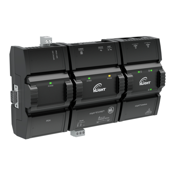
Introduction nLight ECLYPSE Introduction The nLight ECLYPSE is a modular and scalable platform that is used to control a wide range of HVAC applications. It sup- ports BACnet/IP communication and is a listed BACnet Building Controller (B-BC). The nLight ECLYPSE consists of an automation and connectivity server, power supply, and an nLight Interface module. -
Page 11: Acronyms And Abbreviations Used In This Document
Remote Authentication Dial-In User Service REST Representational State Transfer Remote Terminal Unit (for Modbus) SSID Service Set IDentification Transmission Control Protocol User Datagram Protocol Uniform Resource Locator Universal Serial Bus Virtual Private Network Wide Area Network Wi-Fi Protected Access World Wide Web nLight ECLYPSE... -
Page 12: Internet Protocol Suite Fundamentals
However, it is the Transmission Control Protocol (TCP), the most com- monly used internet transport protocol that is used by nLight ECLYPSE IP controllers to communicate with each other. TCP creates a connection-oriented channel between two applications; that is to say the data stream is error-checked, is sorted into the correct sequence (missing data packets are re-transmitted) and this data stream has a port number for addressing a specific application at the destination host computer. -
Page 13: Ipv4 Communication Fundamentals
An alternative to using a fixed IP address is to use the controller’s Hostname Management which allows a controller to be identified by a nickname such as Office_205 instead of the controller’s IP address. The hostname can be used in a Web browser. nLight ECLYPSE... -
Page 14: Networking Basics
16382 255.255.224.0 2048 8190 8190 255.255.240.0 4096 4094 4094 255.255.248.0 8192 2046 2046 255.255.252.0 16384 1022 1022 255.255.254.0 32768 255.255.255.0 65536 255.255.255.128 131072 255.255.255.192 262144 1024 255.255.255.224 524288 2048 255.255.255.240 1048576 4096 255.255.255.248 2097152 8192 255.255.255.252 4194304 16384 nLight ECLYPSE... -
Page 15: Cidr Addressing
Each IP address class has a private address range. Private IPv4 addresses cannot be routed over the Internet. nLight ECLYPSE IP controllers will normally be assigned to a private IP address and are connected to the LAN ports of a router, thereby keeping them behind a firewall from the internet while allowing them to freely communicate to each other and to other trusted devices. -
Page 16: About Routers, Switches, And Hubs
Figure 2: The Way a Router is Connected Changes its Function On some routers, the uplink port is marked as WAN (Wide Area Network) and the numbered ports are to be connected to the LAN (Local Area Network) devices. nLight ECLYPSE... -
Page 17: Network Address Translation / Firewall
Figure 4: Network Segment for HVAC IP Controllers with a Wireless Access Point If a wireless router is unavailable or is out-of-range, an ECLYPSE Wi-Fi adapter can be connected to an ECLYPSE con- troller’s USB port to add wireless connectivity. See Wireless Network Connection. nLight ECLYPSE... -
Page 18: Ip Network Protocols And Port Numbers
Web browser operator interface. Secure Web Configuration Interface: This is the network configuration interface for wired and wireless IP network interfaces. Authentication Port: This is the port on which authentication Radius Server 1812 (UDP) requests are made. nLight ECLYPSE... -
Page 19: Eclypse Services That Require Internet Connectivity
Used to set the controller’s real-time clock Used to provide URL name resolution. The controller by default DNS server 53 (UDP, TCP) uses an internet DNS. If the local network has a DNS, set its IP address in Network Settings. nLight ECLYPSE... -
Page 20: Connecting Ip Devices To An Ip Network
4.6mm (0.18in.) Cable - Without Connectors 100 Crimp RJ 45 Connectors Table 2: Recommended Cable Types to use for the Cat 5e Cable Subnetwork Bus 1. Outer cable diameter – This does not take into account the RJ-45 connector. nLight ECLYPSE... -
Page 21: About The Integrated Ethernet Switch
/ router. Under normal operation, the switch / router disables one of the ports to prevent a packet storm. This is shown below. To Other IP Devices Wired Router / Switch The Router / Switch’s Spanning Tree Protocol has Blocked this Port Figure 6: Wired Network Connection: Spanning Tree Protocol – Normal Operation nLight ECLYPSE... -
Page 22: Connecting The Network Cable To The Controller
Wi-Fi radio signal transmission and reception. Walls attenuate radio wave propagation by an amount that varies with the construction materials used. See Radio Signal Transmission Obstructions for more information on wall materials that can reduce range transmission. nLight ECLYPSE... -
Page 23: About The 2.4 Ghz Ism Band
For example, in the 2.4 GHz band using 802.11g, the channel width is 20 MHz while the channel spacing is 5 MHz. If one Wi-Fi network is using channel 1 that is in close proximity to another Wi-Fi network that is using channel 2, there will be significant inter-channel overlap and interference. Data throughput is reduced as a result. nLight ECLYPSE... -
Page 24: Radio Signal Range
When installing the wireless adapter, it is important to ensure that distances and obstructions do not impede transmission. Metallic parts, such as steel reinforcement in walls, machinery, office furniture, etc. are major sources of field strength dampening. Furthermore, supply areas and elevator shafts should be considered as complete transmission screens, see following figure. nLight ECLYPSE... -
Page 25: Transmission Obstructions And Interference
The following image shows where to install an Wi-Fi Adapter on a metal relay panel or utility box with a controller inside the panel/box. To maximize wireless range, the Wi-Fi Adapter must be installed on the top or side of the panel. nLight ECLYPSE... -
Page 26: Planning A Wireless Network
1. Retrieve a copy of your floor plans and a compass. Figure 14: Copy of floor plan and a compass 2. Mark relevant radio shadings into floor plan such as: fire protection walls, lavatories, staircases, elevator shafts and supply areas. nLight ECLYPSE... - Page 27 Even after careful planning, range and signal tests should be done during installation to verify proper reception at the Wi-Fi Adapter positions. Unfavorable conditions can be improved by changing the antenna position or by adding a router closer to the controller(s). nLight ECLYPSE...
-
Page 28: Eclypse Wi-Fi Adapter Connection Modes
Use Wi-Fi to Eliminate Ethernet Cables Wireless Router Interconnection Through Wi-Fi Internet Router Eliminate Ethernet Cables Figure 17: Leveraging Existing Wireless Infrastructure by Eliminating Ethernet Cables To configure the Wi-Fi client connection mode, see Setting up a Wi-Fi Client Wireless Network. nLight ECLYPSE... -
Page 29: Wi-Fi Access Point
Controller-to- Controller Interconnection : Use Wi - Fi to Wirelessly Connect other Controllers Wireless Access Point Internet Controller Interconnection Through Wi - Fi Router Wired - to- Wireless Bridge Eliminate Ethernet Cables Figure 19: Using an ECLYPSE Controller as a Wireless Bridge nLight ECLYPSE... -
Page 30: Wi-Fi Hotspot
Ethernet ports. This can be used as a solution to ‘jump’ architectural features that are not compatible with wires such as glass atrium and the like. The access point / hotspot can provide Wi-Fi access to other Wi-Fi enabled clients. nLight ECLYPSE... - Page 31 If the access point is a Wi-Fi router: 1. The number of devices is limited by the total number of clients the router is able to support. 2. It can support many controllers acting as wireless to wired bridges. nLight ECLYPSE...
-
Page 32: Wireless Network Commissioning Architectures
Subnet 1 Wi-Fi Wired IP Client Daisy Chain Wi-Fi Client Wi-Fi Access Point Wi-Fi Client Wi-Fi Client Wi-Fi Client Wi - Fi Client Wi-Fi Client Wi-Fi Access Point Wi-Fi Client Wi-Fi Client Figure 24: Client to Access Point Configuration nLight ECLYPSE... -
Page 33: Client To Hotspot Configuration
ECLYPSE Controller Wi-Fi Client Wi-Fi Wired IP Client Daisy Chain Wi-Fi Access Point Wi -Fi Client Wi -Fi Client Wi -Fi Client Laptop 2 Wi-Fi Client Wi-Fi Access Point Wi-Fi Client Wi-Fi Client Figure 25: Client to Hotspot Configuration nLight ECLYPSE... -
Page 34: First Time Connection To An Eclypse Controller
ID: MAC Address Model: NECY -S1000 For example, for a MAC Address of : 76:a5:04:cd:4a:d1 The factory-default name for the Wi-Fi access point is nLight ECLYPSE- CD4AD1 The factory-default hostname is nLight eclypse-cd4ad1.local Figure 26: Finding the Controller's MAC Address nLight ECLYPSE... -
Page 35: Ethernet Network Connection
To Router / Device Next Device Figure 27: nLight ECLYPSE Wired Network Connection: Cat 5e Cables with RJ-45 Connectors are used 2. Connect power to the controller(s). See the controller’s Hardware Installation Guide for how to do so. Wi-Fi Network Connection Once the ECLYPSE Wi-Fi Adapter has been connected to a powered controller, a Wi-Fi hotspot becomes available that al- lows you to connect to the controller’s configuration Web interface with your PC. -
Page 36: Configuring The Controller
Web interface as follows: 1. Open your Web browser. 2. In the Web browser’s address bar, type https://nLight ECLYPSE-cd4ad1.local and click Go. 3. Log in to the controller. Then set the controller’s configuration parameters in the controller’s configuration Web inter- face. -
Page 37: Connecting To The Controller's Configuration Web Interface
It is important to create new user accounts with strong passwords to protect the controller from unauthorized access. See User Management, Securing an ECLYPSE Controller, Supported RADIUS Server Architectures. Next Steps In Network Settings, configure the controller’s network parameters so that they are compatible with your network. See ECLYPSE Web Interface. nLight ECLYPSE... -
Page 38: Supported Radius Server Architectures
Radius based authentication is required, an ECLYPSE controller must act as the Radius server. In addition, third party Radius clients will not be able to connect to the ECLYPSE Radius server. For more information, see FIPS 140-2 Mode. nLight ECLYPSE... -
Page 39: Radius Server Architectures
Credential Database B and C credentials for the Server’s RestService. Each credential database must also have the credentials for each user that will log in to ECLYPSE controller A (for example, administrators, direct connection by users, ENVYSION users, etc.). See User Management. nLight ECLYPSE... -
Page 40: Eclypse-Based Centralized Credential Authentication
Server is lost, users that have previously authenticated themselves with the ECLYPSE controller A’s RADIUS Server credential database on a given controller will still be able to log in to those controllers as their credentials are locally cached. nLight ECLYPSE... -
Page 41: Eclypse Web Interface
The sidebar contains the configuration menus that allow you to view and set the controller’s configuration settings including its IP address, Wi-Fi settings, users, controller’s firmware, and much more. The menus may vary according to the associated device licenses and the user’s access level. These configuration param- eters are password protected. nLight ECLYPSE... -
Page 42: Home Page
1. To change your password, click the profile icon and select Change Password. 2. Enter your current password and click Next. 3. Enter the new password twice to confirm and click Next. Your password is changed. Click the show password icon to see the password you are entering. nLight ECLYPSE... -
Page 43: Network Settings
DHCP server servers. See Domain Name System (DNS). Secondary DNS When making changes to the network settings, click Apply to apply and save the changes. You can click refresh to re- fresh the information in the screen. nLight ECLYPSE... -
Page 44: Wireless Configuration
The range of IP addresses to be made available for Hotspot clients to use. The narrower the range, the fewer hotspot clients will be able to connect due to the lack of available IP addresses. For example, a range where First Address = Last Address nLight ECLYPSE... -
Page 45: Network Diagnostics
Wi-Fi Monitor: shows the current performance of a Wi-Fi connection with another controller. £ Ping Monitor: shows the round trip time it takes for a ping packet to go to an IP address and come back. £ Figure 34: Network Diagnostics – Wi-Fi Monitor nLight ECLYPSE... - Page 46 Receiving data rate from the target Figure 35: Network Diagnostics – Ping Monitor Item Description Ip Address Target Enter the corresponding controller’s IP address for its Wi-Fi interface in Ip Address Target. Start Starts graphing the monitored data Clear Clears the graph nLight ECLYPSE...
-
Page 47: Bacnet Settings
BACnet network as a device object property. Export BACnet Object List Export all controller BACnet variables to a file (.csv). Click to refresh the information in the list. Click Apply to apply and save the changes Apply nLight ECLYPSE... -
Page 48: Routing
Click Apply to apply and save the changes. Network IP Ports This sets the IP network configuration parameters (on-board port) as well as the BACnet Broadcast Management Device (BBMD) and Foreign Device for intranetwork connectivity. Figure 38: BACnet IP Configuration - Network IP Ports nLight ECLYPSE... - Page 49 4. In the Port field, enter the port number for the BACnet service of the BBMD located on the other subnetwork. 5. Click OK. You can also edit or delete a BBMD selected from the list using the Edit icon or Delete icon provided. nLight ECLYPSE...
-
Page 50: Network Ms/Tp Ports
Max Info Frames For the ECLYPSE controller, this should be set to 20. See Setting the Max Master and Max Info Frames. Click to refresh the information in the list. Apply Click Apply to apply and save the changes. nLight ECLYPSE... -
Page 51: Diagnostics
The following Diagnostics tab provides information on live values passing through the RS-485 ports. By default, the live values are displayed. You can stop and restart the streaming of the live values using the Stop Live Values/Start Live Val- ues button. Figure 41: BACnet Diagnostics nLight ECLYPSE... -
Page 52: User Management
Securing an ECLYPSE Controller. Figure 42: Adding Users in Server Mode 1. Click the Add User icon to add a new user or select a user and click edit to edit an existing user. The User Details window is displayed. nLight ECLYPSE... - Page 53 User’s password credential Show/Hide the user’s password credential User must change Select to force user to change their password at the next login. password at next login 3. Click Next. The Roles options are displayed. Figure 44: User Details - Roles nLight ECLYPSE...
- Page 54 ECLYPSE Web Configuration Interface or ENVYSION. Table 3: ECLYPSE Roles BLE Room Device Roles are not available on the nLight ECLYPSE and can be ignored. 5. Click Next. The Welcome Page screen is displayed allowing you to define the user’s landing page that will be dis- played when they login to the controller.
- Page 55 192.168.0.10/#/bacnet, remove the hostname or IP Address so that the URL becomes /eclypse/envysion/index.html or /#/bacnet. 4. Click Save. To edit an existing user, select the user from the list and click the edit icon and to remove, click the delete icon nLight ECLYPSE...
-
Page 56: Password Policy
No matter which port numbers are used, make sure that the port numbers are unused by other services on this controller and that both the RADIUS server and the RADIUS clients use the same port number values. See also IP Network Port Numbers and Protocols. nLight ECLYPSE... -
Page 57: Radius Client Settings
This centralizes access management on the RADIUS server thereby saving time by eliminating the need to add users to each controller individually. The client RADIUS server can be another ECLYPSE controller or a Microsoft Windows Domain Active Directory Server. See Supported RADIUS Server Architectures. nLight ECLYPSE... - Page 58 No matter which port numbers are used, make sure that the port numbers are unused by other services on this controller and that both the RADIUS server and the RADIUS clients use the same port number values. See also IP Network Port Numbers and Protocols. nLight ECLYPSE...
-
Page 59: Single Sign On (Sso) Settings
When Type is set to Single Sign On (SSO), the controller will be defined as the SSO Server dedicated to authentication purposes. Therefore, a single login to the server will authenticate user access to multiple ECLYPSE controllers that are on the same network. nLight ECLYPSE... -
Page 60: Sso Client Settings
The Client Settings tab allows you to select the type of client mode for the Client controller(s). When Type is set to Single Sign On (SSO), the controller will use the SSO server for authentication. Figure 54: Client Settings - Type When Type is set to Local, credentials are added to and managed by this controller. nLight ECLYPSE... - Page 61 In order for the recovery to work, we highly recommend you do not forget your recovery password. If so, a factory reset will be required. Click to copy the access token to the clipboard. Click to refresh the information in the list. Apply Click Apply to apply and save the changes. nLight ECLYPSE...
-
Page 62: Setting Up The Sso Functionality
3. Enter your credentials to log in. The ECLYPSE home page is displayed. 4. In the Users menu, select the Server Settings tab and make sure the Server Mode is set to Off. If not, set the Server Mode to Off and click Apply before proceeding. nLight ECLYPSE... - Page 63 7. In Server IP Address, enter the server IP address of the controller that is configured as the Server (e.g., 192.168.0.10). 8. In Server Https Port, verify that the port number matches the HTTPS port number of the SSO server in System > Web Server (e.g., 443). nLight ECLYPSE...
-
Page 64: Certificate Authentication With Sso
3. Go to your browser settings. For the purpose of this procedure, Google Chrome web browser is used. 4. Scroll down to the bottom of the Chrome Settings page and select Advanced. 5. Select Manage certificates. The Certificates window is displayed. 6. Select the Trusted Root Certification Authorities tab. nLight ECLYPSE... -
Page 65: System Settings
Note: Rebooting the controller will interrupt the operation of any connected equipment and the controller will be offline from the network for the duration of the reboot. Export an audit log in .csv format showing auditable events such as account logins, event ID and description, event type, etc. Export Audit Log Export Audit Log for more information. nLight ECLYPSE... -
Page 66: Updating The Firmware
When a user sends a delete action on the Rest API Rest_Get When a user sends a read action on the Rest API Web_Interface When a user performs an action on the Web interface. The .csv file displays the event details in the following information columns: nLight ECLYPSE... -
Page 67: Location And Time
Figure 62: Example of an exported .csv file of auditable events Location and Time The Location/Time tab is used to configure the system date and time as well as the weather and current location. Figure 63: System Settings – Location, Date, and Time nLight ECLYPSE... -
Page 68: Web Server Access
Click to get the current time a date from an Internet time clock server. Internet connectivity is required for this feature to Time work. Weather On/Off Weather service is not available for nLight ECLYPSE controllers. City Set the city location from which the system will use weather data. Current City Displays the currently selected city Displays the latitude and longitude coordinates of the currently selected city. - Page 69 2. Click Export Authority Public Key to save the certificate on your PC. 3. Save the file on your PC. 4. Distribute this file to all PCs that will connect to this controller. 5. Install the certificate on the PC by double-clicking it in Microsoft Windows Explorer. 6. Click Open. nLight ECLYPSE...
- Page 70 Figure 65: Certificate Security Warning 7. Install the certificate in the Trusted Root Certification Authorities store. Click Install Certificate. Figure 66: Installing the Certificate on the PC 8. Select Place all certificates in the following store. Click Browse. Figure 67: Selecting the Store nLight ECLYPSE...
- Page 71 ECLYPSE Web Interface 9. Select Trusted Root Certificate Authorities and click OK. Figure 68: Selecting the Trusted Root Certification Authorities Store 10. Click Next. Click Finish. 11. Accept the warning. Click Yes. Figure 69: Accept the Warning nLight ECLYPSE...
-
Page 72: Licenses
When you connect to the controller, your browser will ask you to accept the new HTTPS security certificate. Licenses You can import licenses from your PC or a Web server, as well as export an existing license. Figure 70: System Settings – Licenses nLight ECLYPSE... -
Page 73: Fips 140-2 Mode
£ BACnet ports £ Weather Information £ Users reset £ HTTPS Certificates will be lost £ Default username and password £ In addition, enabling FIPS 140-2 mode will have the following impact on the controller to respect compliance: nLight ECLYPSE... - Page 74 The banner states the following message: “This is a U.S. General Services Administration Federal Government com- puter system that is "FOR OFFICIAL USE ONLY.". This system is subject to monitoring. Therefore, no expectation of privacy is to be assumed. Individuals found performing unauthorized activities are subject to disciplinary action includ- ing criminal prosecution.” nLight ECLYPSE...
-
Page 75: Gsa It Security Mode
The Backup and Restore window, shown below, is used to create a backup as well as import and restore a backup. When a backup is created, the file appears in the list as shown in the following figure. Figure 73: System Settings - Backup and Restore nLight ECLYPSE... - Page 76 1. In the Backup & Restore main screen, click Create Backup. The options to create a new backup are displayed. Figure 74: Creating a New Backup 2. In the Backup File Name section, enter the backup file name, and click Next. nLight ECLYPSE...
- Page 77 The restore functionality guides you through a series of well-defined steps to easily import and restore a backup. 1. In the Backup & Restore main screen, click Import and Restore Backup. The restore options are displayed. Figure 76: Restoring a Backup nLight ECLYPSE...
- Page 78 In the Backup & Restore main screen, a Restore button is available next to each backup file. This allows you to restore a selected backup file on your PC. 1. In the Backup & Restore main screen, select the backup file(s) you wish to restore from the list. Figure 78: Restoring a Selected Backup File nLight ECLYPSE...
- Page 79 You cannot restore a “non-FIPS 140-2” to a FIPS 140-2 device because the file is not encrypted and therefore not compatible with the FIPS 140-2 mode. You also cannot restore a backup which was created in a more recent firmware version than the one you are restoring to. nLight ECLYPSE...
-
Page 80: Open Adr Virtual End Node (Ven)
Open ADR Virtual End Node (VEN) The nLight ECLYPSE is available with a software module that embeds Open Automated Demand Response (OpenADR) 2.0a Virtual End Node (VEN) capability directly into the controller, eliminating the requirement for a separate system com- ponent that acts as a VEN. - Page 81 The Automated DR Levels can be configured for specific luminaires, devices or zones using the SensorView software in- terface. Application Requirements The utility VTN server must support OpenADR 2.0a VEN clients. The nECY must have an outbound https connection to the OpenADR VTN IP address (TCP 443). nLight ECLYPSE...
-
Page 82: Nlight Eclypse Bacnet Points
ECLYPSE Web Interface nLight ECLYPSE BACnet Points BACnet points for all nLight devices are automatically generated in the ECLYPSE controller once the network scan is launched. To optimize the automatic BACnet point generation, there is a filter function in the ECLYPSE web interface that will filter certain types of nLight resources to be skipped in the BACnet resources creation process. -
Page 83: Nlight Air Pti
The duration of the PTI can be adjusted using the + and – icons. Click the Start button to begin logging. After the PTI is fin- ished running, it creates a log file that can be downloaded using the Download Logs button. Figure 84: nLight Air PTI nLight ECLYPSE... -
Page 84: Configuring The Eclypse Wi-Fi Adapter Wireless Networks
Configure the controller’s ECLYPSE Wi-Fi adapter mode as a Wi-Fi client as follows. 1. Set Wireless to On. 2. Set the Mode to Client. 3. Click the Find Network icon to search for available access points that are within range. The access points are listed on the right. nLight ECLYPSE... -
Page 85: Setting Up A Wi-Fi Access Point Wireless Network
DHCP server to automatically configure their IP connection parameters. See Wi-Fi Access Point more information. Figure 87: Access Point Wireless Network Settings Configure the controller’s ECLYPSE Wi-Fi adapter mode as a Wi-Fi access point as follows. nLight ECLYPSE... -
Page 86: Setting Up A Wi-Fi Hotspot Wireless Network
BACnet to identify services that are available within the BACnet internetwork. See BACnet/IP Broadcast Management Device Service (BBMD). Figure 88: Hotspot Wireless Network Settings Configure the controller’s ECLYPSE Wi-Fi adapter mode as a Wi-Fi hotspot as follows. 1. Under Wireless Configuration, set wireless to On. nLight ECLYPSE... - Page 87 192.168.0.26 will allow a maximum of 5 clients to connect to the hotspot on a first-to-connect basis. 10. Under Advanced, set the Channel Number, and Wi-Fi Mode. See Wireless Configuration for an explanation of these parameters. 11. Click Apply. nLight ECLYPSE...
-
Page 88: Securing An Eclypse Controller
Account Management and Permissions User accounts must be properly managed to make it harder for an attacker to compromise security, and to make it easier to detect that an attack has occurred. To set user account parameters, see User Management. nLight ECLYPSE... -
Page 89: Fips 140-2 Mode
Additional Measures Update the Controller's Firmware to the Latest Release Always keep the ECLYPSE controller’s firmware up-to-date. The most recent firmware has the latest bug fixes, security updates, and stability enhancements. nLight ECLYPSE... -
Page 90: External Factors
Make Sure that Controllers are Behind a VPN For off-site connections, ensure that users access the controllers through a Virtual Private Network (VPN). This helps to prevent an attack through eavesdropping on the communications channel to steal user credentials. nLight ECLYPSE... -
Page 91: Bacnet Ms/Tp Communication Data Bus Fundamentals
Sig+ Data– Data+ Table 4: Common Identification Labels for BACnet MS/TP Data Bus Polarity for other Manufacturers When interfacing with BACnet MS/TP devices from other manufacturers, refer to the documentation provided with the device to correctly wire the device. nLight ECLYPSE... -
Page 92: Maximum Number Of Bacnet Ms/Tp Devices On A Data Bus Segment And Baud Rate
The solution for the above example is to create two data bus segments connected together by a repeater and then split up the devices between the data bus segments, ensuring again that the maximum number of devices on each separate data bus is not exceeded. See Using Repeaters to Extend the Data Bus. nLight ECLYPSE... - Page 93 Data Bus: Shielded Twisted Pair Cable Electrical System Ground Figure 89: Setting the Baud rate on two Controllers on a BACnet MS/TP Data Bus Segment for Failover Protection To set the baud rate for: ECLYPSE Controllers, see Network MS/TP Ports. £ nLight ECLYPSE...
-
Page 94: Data Bus Physical Specifications And Cable Requirements
EOL terminations to known voltages, this provides increased noise immunity on the data bus by reducing the likelihood that induced electrical noise on the data bus is interpreted as actual data. nLight ECLYPSE... -
Page 95: When To Use Eol Terminations
EOL resistor is installed at other end. All other Devices: - EOL Terminations are DISABLED. Figure 91: Typical EOL Terminations with BACnet MS/TP Thermostats with Biasing Provided by the Controller’s Built-in EOL Termina- tion set to ON nLight ECLYPSE... -
Page 96: About Setting Built-In Eol Terminations
Only a daisy-chained data bus topology should be specified during the planning stages of a project and implemented in the installation phase of the project. A spur is only permitted when it is connected to the data bus through a repeater (see Using Repeaters to Extend the Data Bus). nLight ECLYPSE... -
Page 97: Data Bus Shield Grounding Requirements
– Ground usually at the Building Controller, when present Figure 95: Typical Cable-Shield Grounding Requirements for a BACnet MS/TP Data Bus Segment with an ECLYPSE Controller located at the End of the Data Bus nLight ECLYPSE... -
Page 98: Using Repeaters To Extend The Data Bus
A repeater can only connect two BACnet MS/TP data bus segments even if it has ports to support more than two BACnet MS/TP data bus segments. A repeater can be added anywhere to a data bus segment including the end of the segment as shown below. nLight ECLYPSE... - Page 99 A repeater is counted as a device on each data bus to which it is connected. When third party devices are connected to a data bus segment, the number of devices that can be connected to that data bus segment may be reduced. See Device Loading. nLight ECLYPSE...
-
Page 100: Device Addressing
Both the MAC Address and the Device Instance must be set for each device and are essential for proper BACnet LAN op- eration. For an example of how MAC address, Device Instance number, and Network Number apply to a typical BACnet network, Adopting a Numbering System for MAC Addresses, Device Instance Numbers, and Network Numbers. nLight ECLYPSE... -
Page 101: About The Mac Address
Slave devices cannot accept the token, and therefore can never initiate communications. A Slave can only communicate on the data bus to respond to a data request addressed to it from a Master device. Gaps in slave device MAC Addressing have no impact on BACnet MS/TP data bus performance. nLight ECLYPSE... -
Page 102: About Tuning The Max Info Frames Parameter
Setting the Max Master and Max Info Frames The Max Master and Max Info Frames are parameters used to optimize a BACnet MS/TP Data Bus. This is set in the ECLYPSE Controller and separately with the Supervisor for each connected BACnet MS/TP device. nLight ECLYPSE... -
Page 103: Default Device Instance Number Numbering System For Nlight Eclypse Controllers
Where 364 is the nLight ECLYPSE controller’s unique BACnet Manufacturer ID. This Numbering system is sufficient for a BACnet network that has only one nLight ECLYPSE Controller. For larger BAC- net networks that have more than one controller (to form a BACnet intranetwork), set the MAC Addresses, Device Instance Numbers and Network Numbers according to the numbering scheme below. -
Page 104: Adopting A Numbering System For Mac Addresses, Device Instance Numbers, And Network Numbers
ECLYPSE Controllers when routing is enabled (see Routing). Make sure to add only the devices connected to the MS/TP port of the specific ECLYPSE Controller being configured. Using this numbering system will greatly help to identify those devices that should be added to a given ECLYPSE Controller. nLight ECLYPSE... -
Page 105: Setting The Controller's Mac Address
BACnet MS/TP network(s). The BBMD service on these networks strips out the encapsulation and sends the BACnet message on to the appropriate devices. When sending BACnet messages across a standard IP connection that has an IP router, there must be one BBMD service running on each BACnet MS/TP network. nLight ECLYPSE... -
Page 106: Power Supply Requirements For 24Vac-Powered Controllers
7 volts peak, there is a risk of data corruption and offline events due to the device being incapable of correctly reading data signals from the data bus. Thus, it is important to keep the power supply (transformer) as close to the controller as possible. nLight ECLYPSE... -
Page 107: Techniques To Reduce Ground Lift
When the total load of a number of devices requires a transformer with a rating greater than 100 VA, use two or more £ transformers. Ensure that the load to be connected to each transformer follows the guideline of Step 1 above. nLight ECLYPSE... -
Page 108: 24Vac Power Supply Connection
Ground – At terminals of all devices Transformer must be connected to the Only power supply bus that is grounded. Figure 104: The 24V COM / C Terminal of all Devices must be Connected to the Grounded Power Supply Bus nLight ECLYPSE... -
Page 109: Modbus Tcp Configuration
Modbus TCP device. For this, each Modbus TCP device is identified by its address. About Device Addressing Each slave device must have its own unique address number in the range from 1 to 254. Refer to the device’s hardware installation guide for information about how to set its address number. nLight ECLYPSE... -
Page 110: Modbus Rtu Communication Data Bus Fundamentals
Modbus RTU data bus polarity Data – Data + Data 0V Table 12: Common Identification Labels for Modbus RTU Data Bus Polarity When interfacing with Modbus RTU devices, refer to the documentation provided with the device to correctly wire the device. nLight ECLYPSE... -
Page 111: Data Bus Physical Specifications And Cable Requirements
EOL terminations should only be enabled / installed on the two devices located at either end of the data bus. All other de- vices must not have the EOL terminations enabled/installed. If a Modbus RTU device at the end of the data bus does not have a built-in EOL termination, then add a 120 Ohm resistor across the device’s terminals. nLight ECLYPSE... -
Page 112: About Setting Built-In Eol Terminations
Only linear, daisy-chained devices provide predictable data bus impedances required for reliable data bus operation. Only a daisy-chained data bus topology should be specified during the planning stages of a project and implemented in the installation phase of the project. nLight ECLYPSE... -
Page 113: Data Bus Shield Grounding Requirements
– Ground usually at the Building Controller, when present Figure 108: Typical Cable-Shield Grounding Requirements for a Modbus RTU Data Bus Segment with an ECLYPSE Controller located at the End of the Data Bus nLight ECLYPSE... -
Page 114: Device Addressing
Modbus RTU device. For this, each device connected to the Modbus RTU data bus is identified by its address. About the Device Address Each slave device must have its own unique address number in the range from 1 to 247. Refer to the device’s hardware installation guide for information about how to set its address number. nLight ECLYPSE... -
Page 115: Resetting Or Rebooting The Controller
Resetting or Rebooting the Controller The reset button is located between the RS-458 and Ethernet connectors on an nLight ECLYPSE controller. Depending on the amount of time the reset button is held down, different actions are taken by the controller. -
Page 116: Eclypse Controller Troubleshooting
Double check that the wire connections are correct. does not communicate on Absent or incorrect network Check the network termination(s). Incorrect or broken termination(s) will make the large network termination communication integrity dependent upon a controller's position on the network. nLight ECLYPSE... - Page 117 Connect no more than five devices to a power BACnet MS/TP devices require good power quality. See Power Supply Requirements for 24VAC- supply transformer (for 24V controllers) Powered Controllers. Table 16: Verify that the Following Recommendations have been Carried Out Before Calling Technical Support nLight ECLYPSE...
-
Page 118: Wi-Fi Network Troubleshooting Guide
Router may have a known Upgrade the router’s firmware. See the manufacturer’s Website. the field to interfere with the technical issue signal. Table 17: Troubleshooting Wi-Fi Network Symptoms nLight ECLYPSE... - Page 119 Recovery password is SSO Server is down or a requested in the Web networking or connection Enter your recovery password. Verify the network connectivity. browser. issue has occured. Reconfigure the SSO parameters. See Setting Up the SSO Functionality nLight ECLYPSE...
- Page 120 nLight ECLYPSE_UG_11_EN...
Need help?
Do you have a question about the nLight ECLYPSE and is the answer not in the manual?
Questions and answers