
Summary of Contents for Baer DLX
- Page 1 Data Logger User Manual Doc.-No: E116012215052 Bär Industrie-Elektronik GmbH Siemensstr. 3 D-90766 Fürth Phone: +49 (0)911 970590 Fax: +49 (0)911 9705950 Internet: www.baer-gmbh.com...
- Page 2 COPYRIGHT Copyright © 2015 BÄR Industrie-Elektronik GmbH. All rights, including those origi- nating from translation, (re)-printing and copying of this document or parts thereof are reserved. No part of this manual may be copied or distributed by electronic, mechanic, photographic or indeed any other means without prior written consent of BÄR Industrie-Elektronik GmbH.
-
Page 3: Table Of Contents
Description of the block circuit diagram of modules ......14 3 Functional Description....................15 Functional circuit diagram .................. 15 Data protection and safety ................. 16 Program code ....................16 Setting of parameters (Programming the DLX) ........... 16 3.4.1 Program protection switch ..............17 Pulse processing ....................19 3.5.1 Pulse inputs .................. -
Page 4: Addresses For Menu Item "Info - Table Addresses
Control inputs ....................37 3.10 Outputs ......................38 3.11 Communication ....................39 4 Design ........................40 Sealing arrangements ..................40 4.1.1 Housing for panel mounting ..............40 4.1.2 19"-rack ....................41 Installation diagram .................... 42 5 Commissioning ......................43 Delivery state ..................... 43 Preparation for commissioning ................ - Page 5 7.8.2 Erase memory ..................71 Main menu item “Maintenance” ................72 7.9.1 Set time ....................73 7.9.2 Activate PC-Card .................. 73 7.9.3 Deactivate PC-Card ................74 7.9.4 Set cumulative counter ................. 75 7.9.5 Initiate maximum reset................75 7.9.6 Test display ..................76 7.10 Main menu item “Erase Alarms”...
- Page 6 11.4 Activating a PC-Card ..................92 11.5 Deactivating a PC-Card ..................92 11.6 Removing a PC-Card ..................92 11.7 Data storage on a PC-Card................93 12 Registration of Measurements ................. 94 12.1 Factory settings ....................95 13 Fault Displays ......................97 13.1 LC display ......................
- Page 7 Table of figures Figure 1, Application environment ..................9 Figure 2, Block circuit diagram of modules ............... 13 Figure 3, Functional circuit diagram ................. 15 Figure 4, Program protection switch by housing for panel mounting ........ 17 Figure 5, Program protection switch by 19”-rack .............. 17 Figure 6, Block circuit diagram of impulse processing ............
- Page 8 Figure 48, Inserting a PC-Card ..................91 Figure 49, Main menu item “Display alarms” ..............97 Figure 50, Example “Display alarms” ................99...
-
Page 9: Scope Of Application
Scope of Application Application environment Figure 1, Application environment... -
Page 10: Short Description
Short description The DLX was designed as a powerful device for the registration and proc- essing of electrical impulses from energy meters, flow meters, heat flow processors and similar devices. It is meant for installation in bulk energy supply points, power station injection points, at special contract customers and industrial premises. -
Page 11: Device Description
Device Description Features Display LCD (illuminated supertwist), 4 lines of 20 characters, controlled by keypad or control input ANZ Light emitting diodes 16 inputs (pulse or analogue), (Number / Usage) 7 control inputs, 6 outputs (incl. 2 alarms), 1 PC-Card (memory card), 3 interfaces Keypad 4 keys (Enter, Exit, Cursor-Up, Cursor-Down) 1) Service interface (programming/data retrieval): RS232... - Page 12 Switching between summer automatic and winter time Radio clock optional: external DCF77-Receiver Event buffer min. 780 events Transmission protocols SCTM, IEC 60870-5-102, automatic protocol recognition alternative: Modbus RTU Internal modem optional: PSTN max. 9600 Baud alternative: ISDN, LAN/Ethernet External modem GSM/GPRS: UniMod GSM-4 PSTN:...
-
Page 13: Block Circuit Diagram Of Modules
Block circuit diagram of modules The block circuit diagram below gives an overview of the individual mod- ules of the DLX. Figure 2, Block circuit diagram of modules... -
Page 14: Description Of The Block Circuit Diagram Of Modules
Commands to the micro controller are entered via the keypad. The program protection switch, which is used to protect the parameters of the DLX from alterations, is located on the in- side of the display module. -
Page 15: Functional Description
Functional Description Functional circuit diagram The functional circuit diagram below shows and overview of the individual functions of a DLX device. Figure 3, Functional circuit diagram... -
Page 16: Data Protection And Safety
(see page 95) will be activated. Setting of parameters (Programming the DLX) Parameter settings in the DLX can be altered via the programming software DLXPARA or via the keypad (only certain registers), however only after en- tering a valid password. -
Page 17: Program Protection Switch
For programming of the DLX a PC needs to be connected to the V.24 ser- vice interface of the DLX. Programming of the DLX is only possible with the programming software DLXPARA. For details of the programming software please read the user manual shipped with the software. - Page 18 Please note that the front panel is connected to the CPU board with a flat band cable. The program protection switch is located in the lower right hand corner of the DLX and can be operated by hand.
-
Page 19: Pulse Processing
Pulse processing All impulses or analogues values at the inputs will be counted after de- bouncing and then processed according the table below. The following registers {REG} are used for results : (see Appendix B) Energy For register addresses the following sub-addresses are possible: Pulse inputs Input 1..16 ee = 01..16 Inputs 1..16... -
Page 20: Pulse Inputs
3.5.1 Pulse inputs Pulse inputs and control inputs are subject to signal verification imple- mented in the software, i.e. pulses that fall short of a minimum period of time are not processed. This period can be programmed separately for pulse length and pulse interval length in the range from 10ms to 2000ms in steps of 10 ms for all pulse inputs. - Page 21 The number of digits for energy register is set to 9 (for version 1.04.00 and up). This includes digits to the left and to the right of the decimal point (e.g. with one decimal place : 12345678.9). If an energy register exceeds the value 999999999, it continues at the value 000000000 and a flag will be set in the device status register (of that registration period).
-
Page 22: Analogue Input (Signal Current Input)
Digital: For firmware version from 1.06.00 and up: the average value (50 scans per second) will be send every second to the DLX-CPU: value 0 corresponds to 0mA (threshold: 0,1mA), value 819 corresponds to 4mA (threshold: 4,1mA), value 4095 corresponds to 20mA. For setting of the offset (0mA or 4mA) use the software DLXPARA. - Page 23 Depending on the sign, the incoming pulses are totalled in a positive or a negative register. In the case of a simple sum (only positive inputs) the positive register contains the sum and the negative register contains the value 0. In the case of frequent changes of the direction of energy flow (e.g.
-
Page 24: Pulse Outputs
Apparent demand and cos( ϕ ϕ ϕ ϕ ) 3.5.5 The DLX can calculate the apparent demand and the demand factor cos(ϕ) of any input and total registers. One register each can be defined to hold the active or reactive demand, respectively:... -
Page 25: Maximum Demand Calculation
Tm1. These values are available on the dis- play of the unit. The DLX will store at least the values of the last 20 resets. Using remote data retrieval (currently only available for SCTM protocol), maximum demand values and register readings for the last 9 reset actions can be retrieved. -
Page 26: Pulse Barrier
3.5.9 Pulse barrier With pulse barrier enabled all pulses arriving in a time window around the end of registration period are buffered. These are forwarded in the next reg- istration period, synchronizing all following devices. This is done to accom- plish identical figures at main and control measurement. -
Page 27: Automatic Summertime Switching
(and storage) of an error event. Inside synchronization window an alarm-free window can be defined. When the DLX is synchronized out of the alarm-free window (but inside the syn- chronization window) a warning is generated (alert number: 07/02). Example: SYN window:... -
Page 28: Registration Period
3.6.4 Registration period The registration period is the period of time used to calculate demand val- ues (and energy increment values). At the end of a registration period, the current value of the maximum demand registers will be stored. Subse- quently the maximum demand registers will be set to zero. -
Page 29: Rate Dependent Processing
Rate dependent processing The DLX can process up to 4 energy and maximum demand rates. Please note that there is a differentiation between „number of rates“ (programma- ble) and “rate control” (settable). With “rate control” one can select the method of switching between different rates. -
Page 30: Rate Calendar
3.7.2 Rate calendar The device has a rate calendar with a table for up to 100 public holidays. The internal rates can be transmitted to external devices using the control outputs (Out1 to Out4 or Rel1 and Rel2), e.g. to control other devices. The rate program (settable) is stored in the form of an internal rate calen- dar, which is hierarchically structured in three levels. -
Page 31: Figure 7, Energy Rate (At)
Example: rate control for 4 energy rates and 2 maximum demand rates: Switching times Rates from Energy (AT) Demand (MT) 06:00 10:00 10:00 12:00 12:00 13:00 13:00 16:00 16:00 22:00 22:00 06:00 This rate table relates to the following energy and demand rate curves: Energy rate (AT): Figure 7, Energy rate (AT): Demand rate (MT):... -
Page 32: Rate Control Inputs
3.7.3 Rate control inputs The rate control inputs TR1 to TR4 determine (if desired and if present in the customer specific hardware configuration) the currently active energy rate and maximum demand rate. The usage of inputs and the correlation of input states to rates can be programmed freely (settable). -
Page 33: Storage Of Measurements
3.8.1.2 Unit warm start The DLX unit performs a warm start (message in the display: “System warm start”) under the following conditions: •... -
Page 34: 3.8.1.3 Unit Cold Start
3.8.1.3 Unit cold start The DLX unit performs a cold start (message in the display: “System cold start” under the same conditions as above, if the internal RAM memory could not be buffered by the GoldCap (minimum of 7 days without power supply voltage). -
Page 35: Capacity Of Internal Memory
3.8.4 Capacity of internal memory Depending on parameter settings (DLXPARA) the individual areas of inter- nal memory have the following capacity: Device parameters: 1 set of parameters Spontaneous events: Min. 780 Min. 20 (depends on the number of defined input Resets (billing data): channels and totals) ×... -
Page 36: Capacity Of Backup Memory (Pc-Card)
3.8.5 Capacity of backup memory (PC-Card) Due to technological and administrational reasons the whole memory of a PC-Card is divided into sectors. Data is always written or erased by com- plete sectors. Depending on the card type the following sector sizes are available: •... -
Page 37: Control Inputs
Control inputs The DLX unit can have up to 7 control inputs (Ctl1..Ctl7). These inputs are by default of the S0 type (also called IES), but optionally they are available in wipe technology (IEW). Control inputs are programmed and activated by the software application DLXPARA. -
Page 38: Outputs
3.10 Outputs The DLX data logger (remote metering device) can have up to 6 freely pro- grammable outputs, which are available in wipe technology (Out1 to Out4, type IAW) and as mechanical relays (Rel1 and Rel2). Corresponding light emitting diodes (LED) in the display show the state of each output (output closed or active: LED is lit). -
Page 39: Communication
Programming is only by service interface possible. An exact description of all interfaces is contained in section “8 Interfaces” and section “9 Modem/Com2 (Optional)” The DLX currently supports three different protocols:: • SCTM • IEC 60870-5-102 •... -
Page 40: Design
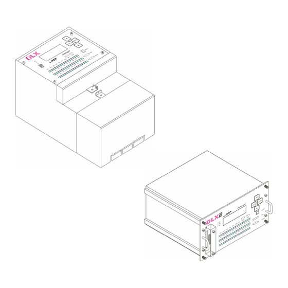
Design Sealing arrangements 4.1.1 Housing for panel mounting The keypad can be sealed by two sealing screws in the upper left and lower right corner of the keypad. The sealing wire needs to be fed through the whole in the enclosure and through the sealing screw and a seal needs to be attached to the wire. -
Page 41: 19"-Rack
4.1.2 19"-rack At the 19“-rack the keyboard and the back are sealed using sealing screws (four at front, six at back). The complete unit then can be plugged into the 19“-rack and fixed using four knurled screws (see M3 thread at front). The eight sealing screws at the sides must not be removed! To uncover the parameter switch remove the sealing screws at the back. -
Page 42: Installation Diagram
Installation diagram Figure 13, Dimensions of mounting points... -
Page 43: Commissioning
Install the DLX at the designated measurement location. Connect the DLX to the mains supply voltage. The DLX will start immediately with its operation, based on the factory settings as per section “Factory settings” (see page 95). Modify the measurement parameters and device parameters with the software... -
Page 44: Supply Voltage
The actually version of DLX contains a wide range power supply, that can- not be adjusted! The supply voltage of old DLX can be selected using a slide switch inside Old Version the housing. Possible voltages are 100/115VAC and 200/230VAC. Please pay attention to use the correct setting for your supply voltage. -
Page 45: Terminals
Figure 16, Location of the terminals (Housing for panel mounting) Figure 17, Location of the terminals (19”-rack) 5.4.2 Connector X1 (Supply voltage) Type of connector: Combicon MSTB2,5/3-ST-5,08 (Phoenix) Function: DLX mains power supply connector Supply voltage: 60VDC – 270VDC and 85VAC – 265VAC Fuse: T 2A 250V Power consumption max. -
Page 46: Connector X2 (Control Inputs, Relay Outputs)
5.4.3 Connector X2 (Control inputs, relay outputs) Terminal type: Combicon MSTB2,5/10-ST-5,08 (Phoenix), 2 per input and 3 per output Function: Control inputs (Ctl1 to Ctl7, terminal 1 to 14) Relay outputs (Rel1 and Rel2, terminal 15 to 20) Input/output types: 7 input modules (IES or IEW) 2 mech. -
Page 47: Connector X3 (Pulse Inputs 1-6, Outputs 1-4)
5.4.4 Connector X3 (Pulse inputs 1-6, outputs 1-4) Terminal type: Combicon MSTB2,5/10-ST-5,08 (Phoenix), 2 per input / output card Function: Inputs (In1 to In6, terminal 1 to 12) Electronic outputs (Out1 to Out4, terminal 13 to Types of inputs / outputs: 6 input modules (IES, IEW, IED, signal current) 4 output modules (solid state IAW el., max. -
Page 48: Connector X4 (Pulse Inputs 7-16)
5.4.5 Connector X4 (Pulse inputs 7-16) Terminal type Combicon MSTB2,5/10-ST-5,08 (Phoenix), 2 per input card Function: Inputs (In7 to In16, terminal 1 to 20) Input types: 10 input modules (IEW, IES, IED, signal current) Terminal Description Pulse input In7– Pulse input In7+ Pulse input In8–... -
Page 49: Connectors X5, X6 And X7
5.4.6 Connectors X5, X6 and X7 X5 (modem interface “Com2”): from page 84 X6 (data interface “Com1”): from page 79 X7 (data interface “Com2”): from page 79, for 19”-rack only 5.4.7 Input and output modules Input and output modules convert the pulse types and voltage levels of commonly used signals in metering technology into TTL signals used by the micro controller (and vice versa). - Page 50 = 10msec). Digital: For firmware version from 1.06.00 and up: the average value (50 scans per second) will be send every second to the DLX-CPU. The following types are used as output modules: IAW el. Pulse output type „wipe“ (solid state, Out1 to Out4) Electronic outputs of type wipe behave the same as relay contacts, i.e.
-
Page 51: Operation
Operation Display Figure 22, Layout of operation controls and indicators 6.1.1 Keypad Moves the scroll list to the next value (in the standard display mode); Activates the selected menu item (in menu mode); Stores the previously set parameter values (in individual menus); Moves the cursor one position to the right (in individual menus). -
Page 52: Light Emitting Diodes (Led)
"In1" to „In16" represent the state of the corresponding pulse input; Exception: analogues inputs for firmware version from 1.06.00 and up: the LED’s show whether the DLX is receiving a data telegram (every second). • "Al1" blinks when an alarm of class1 (warning) has occurred (see „Fault Dis- plays“, page 97). -
Page 53: Standard Display Mode
6.1.3 Standard display mode Figure 23, Standard display mode Interpretation of the standard display mode Line Digit Information Format Explanation 1 and 2 01 to 31 Date display: Day 3 to 5 Month JAN, FEB, MAR, Date display: Month APR, MAY, JUN, JUL, AUG, SEP, OCT, NOV, DEC 6 and 7... -
Page 54: Menus
Menus Flow diagram Figure 24, Flow diagram of menus... -
Page 55: Legend Of Flow Diagrams
The menus After powering up, the DLX shows the standard display (see page 53). Press to go to the menu item „Select language“ (see page 58). Press to go to the main menu (from page 60). Press to start the scroll list (if a scroll list has been programmed via DLXPARA, see page 59). -
Page 56: Password Input
Password input Figure 26, Flow diagram for password input Several menu items (“Set Parameters“: “Factory Settings“ (unit restart) and “Erase Memory“, as well as “Maintenance”: “Set Time“ ,“Activate PC-Card“, “Deactivate PC-Card“, “Set Cumulative Counter“, “Initiate Max. Reset“) re- quire a password for their activation. The following passwords are supported: •... - Page 57 Once the last digit has been selected and the key has been pressed, the DLX checks the entered password. If the password was entered correctly, the DLX will activate the relevant menu item.. If the password was incorrect, input returns to the first digit of the password.
-
Page 58: Select Language
Each press of the key or the key scrolls to the next language. Which languages are available ? The DLX currently supports the languages German, English, French and Dutch. Selecting a language Press the key to select the language. Afterwards the standard dis- play is shown in the selected language. -
Page 59: Scroll List
Scroll list Figure 28, Flow diagram for the scroll list Selecting the scroll list (if programmed) The first entry of the scroll list is always shown in line 3 and 4 of the stan- dard display. Press the key to show the second entry of the scroll list in the dis- play. -
Page 60: Main Menu Item "Show Alarms
Content of the scroll list Programming of the scroll list can only be done with the programming soft- ware DLXPARA. An entry into the scroll list consists of the scroll list entry text, the related value and a physical unit: •... -
Page 61: Main Menu Item "Info
Main menu item “Info” How to get there Press the key twice when in the standard display and then press the key. What does the display show ? The display will show the current values (cumulative and current energy, demand and pulses), the load profile values from the registration period (Tm1 or Tm2: energy values, increments or demand values) as well as bill- ing data, spontaneous events, table addresses and information about the current firmware version. -
Page 62: Current Values
What will be shown ? The display will show the cumulative (settable) and the current (not settable) energy values as well as the demand values of the DLX for the current and the previous (last) registration period Tm1 or Tm2 (if present) for all inputs (I) and totals (S) stored in that registration period. -
Page 63: Load Profiles Values
Press the key once when in menu “Info” and then press the key. The DLX enters the menu item selected. Changing the parameters keys can be used to select the registration period (Tm1/MP1 or Tm2/MP2), the input, the date and time and to select apparent energy or... - Page 64 What will be shown ? After entering the menu item the DLX will display the demand values, en- ergy values or increments of the last registration period Tm1/MP1 or Tm2/MP2 (if present) for all inputs (I01 to I16), totals (S01 to S04), appar- ent demand (X01 or X02) and cos( ϕ...
-
Page 65: Billing Data
Press the key twice when in menu “Info” and then press the key. The DLX enters the menu item selected (the one surrounded by two ar- rows). There will be three submenu items: • Increment counter value: consumption (energy) at the billing period •... -
Page 66: 7.7.3.1 Increment Counter
When displaying billing data, the values are shown depending on the rate, which can be selected. Each entry can only be selected by the secondary reset index (0..99), the primary reset index (1..12, settable) will be dis- played automatically. 7.7.3.1 Increment counter How to select „increment counter”... -
Page 67: Spontaneous Events
“Info” and then press the key. The DLX enters the menu item selected. What will be shown ? The DLX will show the spontaneous events on the display. For more infor- mation see " Fault Displays " on page 97. Explanation:... -
Page 68: Figure 36, Flow Diagram For Menu Item "Info" (Table Addresses)
The DLX enters the menu item selected. Changing the parameters keys can be used to select values for address and the index. What will be shown ? DLX will show the selected table addresses on the display. For more infor- mation see appendix B. Explanation: Example: Adr.:... -
Page 69: Version
“Info” and then press the key. The DLX enters the menu item selected. What will be shown ? The DLX will show the firmware version, the release date and the check- sum of the firmware. -
Page 70: Main Menu Item "Set Parameters
If the program protection switch is in position "Set Disable" (programming blocked, secured certification mode), the message “programming disabled” will be displayed. The DLX will exit the menu item without executing a sys- tem restart. -
Page 71: Erase Memory
“Really erase PP, RST and SP ?”. Press the key to confirm. The DLX unit will now check the state of the program protection switch (see page 17). Only if the switch is in position “Set Enable” will the memory be erased. -
Page 72: Main Menu Item "Maintenance
Main menu item “Maintenance” Figure 40, Flow diagram for menu item “Maintenance” How to get there Press the key four times when in standard display then press the key. Now you can choose one of six additional sub menu items: •... -
Page 73: Set Time
(see „Password input“ on page 56) the function will be executed. What can be done ? You can set the date and time of the internal real time clock of the DLX unit. Setting the time You can set the day (DD), the month (MMM), the year (YYYY), the hour (hh) and the minute (mm), one after the other. -
Page 74: Deactivate Pc-Card
When deactivating a PC-Card, the recording of information on the card will be terminated, the administration information will be updated and the virtual interface between the DLX unit and the PC-Card will be deactivated. If the PC-Card is removed from the DLX unit without deactivating it, then the ad- ministration information is incomplete and the PC-Card cannot be read by other software. -
Page 75: Set Cumulative Counter
7.9.4 Set cumulative counter How to get there Press the -key three times when in menu item “Maintenance” and then press the key. The function "Set cumulative counter" is password protected. Password protection The function “Set cumulative counter“ can be activated with either the password for PARAMETERS or the password for SET. -
Page 76: Test Display
The test includes all segments of the LC display, the background illumina- tion and all light emitting diodes of the DLX. First the illumination of the dis- play will be switched off and all LEDs will be lit. Then the display illumination is switched back on and all segments are switched to black. -
Page 77: Interfaces
(the default protocol for the service interface is always the IE60870-5-102 protocol). The DLX unit will switch to the default protocol after each programming ac- tivity and after 5 minutes with no communication on the relevant interface. -
Page 78: Service Interface
Service interface The service interface is used to program the DLX unit and to retrieve data with a fixed baud rate (9600 baud). It is implemented as a 25 pin SUB-D connector (female) according to ISO2110, the pin allocation is according to V.24/RS232C/DIN 66020. -
Page 79: Data Interface Com1 And Com2
Output Output (data terminal ready) 8.3.3 Pin allocation RS232 (Com1/X6 at 19”-rack only) For the connection between the DLX and a PC, a special cable (5 wires) is required. Identification: Phoenix 5 pins PSC 1,5/5-M. DLX (5 pins, male) cable PC (25 pins, male) Input/Output Pin No. -
Page 80: Pin Allocation Of The M-Bus Data Interface
Connection: via terminals The distance between the DLX and the next M-Bus repeater unit can ex- ceed 5 km. The maximum distance depends on the line conditions and the current burden on the M-Bus. With sufficient line diameter, twisted lines and limitations on the baud rate, up to double the value of the above mentioned distance can be achieved. -
Page 81: Pin Allocation Of The Fiber-Optic Connector
8.3.5 Pin allocation of the fiber-optic connector Using the fiber-optic connector (for fiber-optic transmission), the unit can be read via 820nm optical fiber (glass). Figure 43, Fiber-optic connector • Wave length: 820nm • Transmitter (TD): transmits light • Receiver (RD): receives light •... -
Page 82: Pin Allocation Of The 20Ma/Cs Interface (Passive)
Communication protocol: SCTM or IEC 60870-5-102 (alternatively Modbus RTU) Pin allocation at housing for panel mounting (Com2/X5 or Com1/X6) and at 19”-rack (only Com2/X7): DLX (5 pins, male) Function Pin No. – 20mA passive, RTX – + 20mA passive, RTX + —... -
Page 83: Pin Allocation Of The Rs485 (2 Wires)
(alternatively Modbus RTU) • Termination (120 ): none Pin allocation at housing for panel mounting (Com2/X5 or Com1/X6) and at 19”-rack (only Com2/X7): DLX (5 pins, male) Function Pin No. B (–) A (+) A (+) Bridge to 2 B (–) Bridge to 1 Baud rate: 300 to 9600 Baud Pin allocation at 19”-rack (only Com1/X6):... -
Page 84: Modem/Com2 (Optional)
Modem/Com2 (Optional) The DLX can be optionally equipped with an internal modem: • L834 (PSTN modem LGO 834) at housing for panel mounting only • MOD (PSTN modem UniMod) at 19”-rack and housing for panel mounting • ISDN (ISDN modem) •... -
Page 85: Pin Allocation Of The Modem Interface
9.1.2 Pin allocation of the modem interface The connection between the modem interface (terminal X5, device type DLX..-MOD-..) and a telephone line uses a telephone cable of type RJ12 with a connector of type TAE6N. Code RJ12 — — Figure 44, Pin allocation of the PSTN telephone cable Exception: Devices in housing for panel mounting (year of construction until 2005, de- vice type DLX...-L822/L832/L834-...):... -
Page 86: Isdn Modem
ISDN Modem 9.2.1 Default settings After delivery the following settings are active in the ISDN modem: • S0=1 Respond after one ring • &D0 Ignore DTR • B-Chanel Protocol X.75-NL • **BSIZE=512 Block size 512 Byte • **MSN=* MSN non active •... -
Page 87: Lan/Ethernet Connection
Only the IP-address must be altered in field: via DLXPARA, menu: Communications: Modem init. String (Com2): AT#IP=a.b.c.d (click on “Set”-button, turn off DLX and after some seconds o again). For more detailed information (e.g. set gateway: AT#GW=a.b.c.d ) please consult the manual shipped with the software DLXPARA. -
Page 88: Dcf77 Receiver (Optional)
DCF77 aerial/receiver unit AWS0 from the company “Meinberg Funkuhren“ (Germany). The receiver module requires a +12VDC auxiliary voltage and it can be connected to a S0 control input of the DLX. Figure 47, DCF77 receiver module AWS0 10.1... -
Page 89: Commissioning
If you have good reception , the DLX display will show a static symbol " " latest after 3 minutes. A blinking symbol " " indicates disrupted... -
Page 90: Pc-Card
PC-Card 11.1 Permitted PC-Card's • Standard: JEIDA/PCMCIA • Type: SRAM battery backed Flash Memory-Card (AMD, D Series) • Capacity: up to 4MByte 11.2 Treatment advice for PC-Cards Noncompliance with the following advice can lead to destruction of the PC-Card. • Do not bend or fold the PC-Card or subject it to similar conditions. -
Page 91: Inserting A Pc-Card
Slide the card into the slot and press carefully until the PC-Card reaches the final position (PC-Card and ejection button are aligned, see arrow After inserting the PC-Card it needs to be activated by the DLX in or- der to use it for storage purposes. -
Page 92: Activating A Pc-Card
Activation includes the following actions: The DLX determines type and capacity of the PC-Card. The DLX checks whether the capacity of the card is sufficient for the pro- grammed number of counters and days for the registration period buffer. Once the PC-Card has been found to be suitable, it will be formatted to ensure that recording always takes place on an empty PC-Card. -
Page 93: Data Storage On A Pc-Card
11.7 Data storage on a PC-Card The following information will always automatically be stored on a PC-Card (independent from the program parameters of the unit): • Spontaneous events: the PC-Card will always contain at least the last 100 events. • Billing data: the PC-Card will always contain at least cumulative rate less counter values of the last 4 reset instances. -
Page 94: Registration Of Measurements
Registration of Measurements The device starts to register measurements immediately after the power supply is switched on. This data will be stored together with timestamps and device status in the registration period buffer according to the selected parameters (the factory settings will be used when the unit starts for the first time). -
Page 95: Factory Settings
12.1 Factory settings List of the most important factory settings (basic settings and software settings) on delivery or after a unit restart: Date: Saturday, 1. January 2011 Time: 00:00:00 Device identifier: 0000000000000000 Number of input channels: max. 16 (according to order, all activated) Number of totalling units (sums): 0 Differential totals: Apparent demand reg./cos( ϕ... - Page 96 Periodic buffers: Registration period 1 Tm1: max. number of inputs activated demand values, 4 digits Pulse conditioning: 30ms min. pulse duration 30ms min. pulse interval Output pulses: 90 ms pulse duration 110 ms pulse interval PC-Card: Not registered Summer time switching: On (switching from 02:00 to 03:00 on the last Sunday in March and from 03:00 to 02:00 on the last Sunday in October) Rate control:...
-
Page 97: Fault Displays
LC display Use the menu item Main menu item “Show Alarms“ (see page 60) to dis- play all warnings and device faults that have occurred. The DLX uses line 3 and 4 to display relevant information. Figure 49, Main menu item “Display alarms”... - Page 98 02/01 CPU prog. memory Program memory (EPROM) faulty checksum error Action: The DLX must be sent to the manufacturer for service 02/02 Parameter memory Data error in the parameter memory checksum error Action: The DLX must be sent to the manufacturer for service...
- Page 99 Class Message on the display Description CPU-RAM 82/02 Error in internal CPU-RAM error Action: The DLX must be sent to the manufacturer for service 82/03 CPU-Flash-Memory Error in CPU Flash memory Error Action: The DLX must be sent to the manufacturer for service...
-
Page 100: Light Emitting Diodes (Led's)
13.2 Light Emitting Diodes (LED’s) 13.2.1 LED AL1 Warning The LED „AL1“ blinks after a fault of class „W“ (warning) has occurred. Af- ter manually clearing of the error message the LED „AL1“ goes off. Excep- tions to this rule are the warnings 03/01, 03/02, 06/xx and 8E/xx where the LED “AL1”... -
Page 101: Technical Data
Technical Data Connections In-/Outputs ..........3 pluggable terminal groups of 20 poles each Power supply ......... pluggable terminal group of 3 poles Interfaces service interface ..... V.24: RS232 SUB-D 25 poles data interface ....V.24: RS232 SUB-D 25 poles (Com1 or Com2) ..... or 20mA/CS or M-Bus or fiber-optic terminal ........ - Page 102 Signal current input (0..20mA) Current ......... min.: 0mA (:= 0Hz) max.: 20mA (:=20Hz) Accuracy ......±1% Frequency ......max. 20 pulses/second (up to version 1.05.06) Data telegrams ..... 1 per second (from version 1.06.00 and up) Threshold ......0,1mA (from version 1.06.00 and up) Signal current input (4..20mA) Current .........
- Page 103 Internal real time clock Basic clock rate ........32,768kHz Calendar features ........Leap years, summer-/wintertime day, month, year, hour, minute, second Accuracy/ deviation ........ max. 30sec./month at 25° C (10ppm) Power failure reserve ......min. 7 days (GoldCap) External radio clock (optional) Type ............
- Page 104 RS485 interface (2 or 4 wires; optional) Standard ..........ANSI/TIA/EIA-485-A-98 Voltage ........... 0VDC / 5VDC Number of partner ........max. 32 Cable length ........... max 1,2km Baud rate ..........300 to 9600 baud Termination(120 ) ......... none Protection against voltage and other disturbances Protective measures according to VDE 0701: Protective earth impedance ..
- Page 105 Environmental conditions Permissible environment temperature: During operation ......-10° C to +70° C During transport and storage ..-20° C to +80° C Humidity: During operation ......max. 95% relative humidity During transport and storage ..max. 95% relative humidity Condensing ........
-
Page 106: Glossary
Unusual event during operation of the device (e.g. power failure, register overflow etc.). Alarm class Differentiation of alarms by importance. The DLX knows the alarm classes “warning” for non critical or operational disturbances and “device fault” for grave errors. Alarm group Division of alarms into functional groups, e.g. - Page 107 Digit A number representing a value from 0..9 in a decimal numbering system. Energy values are often processed with 8 digits, i.e. resulting in a value range from 0 to 99999999. Energy register Contains measured energy values in physical units, e.g. kWh, kvarh, ° C, etc.
- Page 108 Pulse weighting Converts pulses into physical units, e.g. by using transformer ratios and meter constants. Pulse input Receives pulses transmitted by meters. Different pulse types are possible, e.g. S0, wipe or bi-current. Radio clock Component of the data logger unit that receives the current time via radio from an official transmitter and adjusts the device time accordingly.
- Page 109 Restart, unit restart Resets all parameters to factory settings. The storage area for measured values is cleared on restart. (see also „cold start“ and „warm start“) Rolling registration period Operational mode in which the registration periods overlap each other. Ex- ample: the average maximum demand value of the last 15 minutes is calcu- lated every 5 minutes.
- Page 110 Subject to change without notice!
- Page 111 Appendix A Data Retrieval Protocols E116012215052...
- Page 113 Rate information (programmable) ..................38 2.4.9 Selection of standardized ASDU..................39 2.4.10 System information in control direction: request (from the central unit to the DLX) ..40 2.4.11 Basic application functions ....................41 Modbus RTU Protocol ..................... 42 Telegram processing ......................42 Telegram structure ......................
-
Page 114: Data Retrieval Protocols (Amr)
Modbus RTU ble only at the interfaces Com1/Data and Com2/Modem) The DLX unit automatically detects the retrieval protocol (for SCTM / IEC 60870-5-102 only). When using the direct interfaces (service interface or data interface) the first telegram will be lost in the case of a protocol change ( the modem interface can change the protocol without losing a telegram). - Page 115 1001 1101 0010 0110 1010 1110 0011 0111 1011 1111 In the DLX unit the device status is contained in 2 bytes: Byte 1 Byte 2 Character 1 Character 2 Character 3 Character 4 T-Bit U-Bit M-Bit A-Bit S-Bit NP-Bit...
- Page 116 Meaning of individual bits: Byte-Nr. Bit-Nr. Content Explanation Byte 1 Bit 7 T-Bit Summertime switching, setting the time Bit 6 U-Bit Shortened registration period due to power failure or time change Bit 5 M-Bit Parameter change Bit 4 A-Bit Alarm or error message (collective message) All warnings and device faults Exception: Warnings 03/02 “power dip”...
- Page 117 Register status in the registration period data block In each registration period the DLX stores a register status of 1 byte (2 characters) for each entry in the periodic buffer. This status is stored in the same format as the device status (hexadecimal notation):...
- Page 118 List of addresses for SCTM -00 Current date and time (resolution of minutes) Table value: YYMMDD: Year Month Day Weekday (1:= Monday, 7:= Sunday) hhmm: Hour Minute Example: Expl.: Date: 01. February 1998 Weekday: Sunday Time: 03:02 -01 Settings for change from wintertime to summertime Table value: Month Weekday (1:=Monday, 7:= Sunday)
- Page 119 Reserved for future use Table value: U: Flag Example: Expl.: Reserve Synchronization mode Table value: S: Synchronization flag 0- Synchronization not possible 1- SYNC input active 2- Synchronization via radio clock receiver Example: Expl.: Synchronization is done via SYNC input Synchronization window surrounding the end of a registration period Table value: Length of the synchronization window in seconds...
- Page 120 Cumulative energy counter reading at the end of the last registration period (MP1 or MP2) m: Registration period (m:=0, 1) 0 Registration period MP1 1 Registration period MP2 Energy rate (t:=0, 1, 2, 3, 4) 0 Total 1 Energy rate 1 2 Energy rate 2 ...
- Page 121 20m -xx Demand values of the current registration period m: Registration period (m:=0, 1) m:=0 0 Registration period MP1 1 Registration period MP2 m:=1 xx: desired value (Counter/Total) 00 Counter 1 01 Counter 2 ... etc. 15 Counter 16 64 positive Total 1 65 positive Total 2 66 positive Total 3 67 positive Total 4...
- Page 122 21m -xx Demand of the last registration period m: Registration period (m:=0, 1) 0 Registration period MP1 1 Registration period MP2 xx: desired value (Counter/Total) 00 Counter 1 01 Counter 2 ... etc. 15 Counter 16 64 positive Total 1 65 positive Total 2 66 positive Total 3 67 positive Total 4...
- Page 123 22m -xx Current counter status (for version 1.04.00 and up) m: Registration period (m:=0,1) m:=0 0 Registration period MP1 1 Registration period MP2 m:=1 xx: desired value (Counter/Total) 00 Counter 1 01 Counter 2 ... etc. 15 Counter 16 64 positive Total 1 65 positive Total 2 66 positive Total 3 67 positive Total 4...
- Page 124 22m -xx Current status for cos(φ) (for version 1.04.00 and up) m: Registration period (m:=6,7) M:=6 6 Registration period MP1 7 Registration period MP2 m:=7 xx: desired cos(φ) 00 cos(φ)1 01 cos(φ)2 Table value: b7b6b5b4b3b2b1b0: Status b0 to b7 usually have the value „0“. Exception: b1 = ‘1‘...
- Page 125 24m -xx Total cumulated apparent demand for the current registration period m: Registration period (m:=0, 1) m:=0 0 Registration period MP1 1 Registration period MP2 m:=1 xx: Apparent demand (xx:=0, 1) 00 Apparent demand 1 01 Apparent demand 2 Table value: dddddddd: Total cumulated apparent demand Example:...
- Page 126 Reset: Maximum of apparent demand, Minimum of cos(φ) Reset index (r:=0 to r:=9) t:=1 0 current maximum / current minimum 1 last reset t:=4 2 second last reset ... etc. Demand rate (t: =1 to t:=4) 1 Demand rate MP1 2 Demand rate MP 2 ...
- Page 127 Reset: Maximum and timestamp for t:=0 to t:=4 (modified from Version 1.04.00 and up) desired reset index (r:=0 or r:=1 to 9): t:=0 0 current maximum 1 last reset t:=4 2 second last reset ... etc. demand rate (t:=0 to 3 for rate 1 to 4) up to version 1.03.08 0 demand rate MP1 1 demand rate MP2...
- Page 128 Reset: counter value at the time of the reset for t:=5 to t:=9 (modified from version 1.04.00 and up) desired reset index (r:=0 or r:=1 to 9): t:=5 0 current counter values 1 last reset t:=9 2 second last reset ...
- Page 129 Reset: cumulated maximum (from version 1.04.00 and up) desired reset index (r:=0 or r:=1 to 9): t:=1 0 current counter values 1 last reset t:=4 2 second last reset ... etc. demand rate (t:=1 to 4) 1 demand rate 1 2 demand rate 2 ...
- Page 130 Number of energy rates d: Number of demand rates Example: Expl.: The DLX is currently programmed to use 2 energy rates and 2 demand rates. -03 Number of apparent demand calculations Table value: s: Number of apparent demand calculations Example: Expl.:...
- Page 131 Number of analogue inputs (from version 1.06.00 and up) Table value: A: Number of analogue inputs Example: Expl.: The DLX is currently programmed to use 4 analogue inputs. Pulse weighting for energy (numerator) xx= 00 for pulse input 1 xx= 01 for pulse input 2 …...
- Page 132 Pulse weighting for totaling units: common divisor of the negative pulse output xx= 00 for totaling unit 1 xx= 01 for totaling unit 2 … xx= 03 for totaling unit 4 Table value: Example: Note: value:=0 → the pulse output is disabled Pulse weighting for totaling units: numerator for inputs y= Index of the totaling unit y= 00 for totaling unit 1...
- Page 133 Analogue inputs: setting minimum value (from version 1.06.00 and up) xx: desired value (input) 00 Counter 1 01 Counter 2 ... etc. 15 Counter 16 Table value: Example: Expl.: Minimum value: -1000 Analogue inputs: setting maximum value (from version 1.06.00 and up) xx: desired value (input) 00 Counter 1 01 Counter 2...
- Page 134 Terminal assignment (from version 1.03.08 and up) xx= 00 Out1 xx= 01 Out 2 xx= 02 Out 3 xx= 03 Out 4 xx= 04 Rel 1 xx= 05 Rel 2 Table value: Example: Note: The following values are possible: S1+, S2+, S3+, S4+ positive pulse output for totaling unit 1 to 4 S1-, S2-, S3-, S4- negative pulse output for totaling unit 1 to 4 MPA1, MPA2 outputs for registration periods MP1 and MP2 RSTA reset output...
- Page 135 MMM: Month YYYY: Year Example: Expl.: The version date of the DLX is the 9th of January 1998 Manufacturer name Table value: Device status of the registration period (from version 1.03.08 and up) desired registration period Table value: S15 S14...
- Page 136 SRAM and has a capacity of 256 kByte. Example 2: Expl.: The last card that was successfully activated in the DLX was of type SRAM and had a capacity of 4 MByte. If no card has been successfully activated the DLX will send:...
- Page 137 Load profile storage depth in internal memory (from version 1.03.08 and up) y=2 for load profile MP1 y=3 for load profile MP2 y=4 for load profile MP3 (always 0, the DLX does not have a third load profile) Table value: Example: Expl.:...
- Page 138 Assignment of load profile storage areas Load profile MP1 Load profile MP2 Load profile MP3: not implemented in DLX 00 for the first three codes (0, 1, 2) 01 for the next three codes (3, 4, 5) K/3 for codes K, K+1, K+2...
- Page 139 -00 Number of stored values per registration period (from version 1.03.08 and up) Table value: for load profile MP1 for load profile MP2 for load profile MP3 (not supported by DLX) Example: Expl.: 018: load profile MP1 stores 18 values, 008: load profile MP2 stores 8 values, 000: load profile MP3 stores no values.
- Page 140 Reset blockage in number of registration periods MP1 Table value: RRR: Reset blockage in number of registration periods MP1 Example: Expl.: At least 3 registration periods MP1 need to pass between two resets Automatic Reset (yes/no) Table value: A: Flag automatic resets are disabled automatic resets are enabled Example:...
- Page 141 Time and Summertime bit in the device status of the registration period Table value: S: Summertime flag 0: correspond to the state at the end of the registration period (DLX standard) 1: correspond to the state during the registration period Example: Expl.:...
- Page 142 Radio clock signal (from version 1.04.00 and up) Table value: f- State of the radio clock signal interpretation Radio clock is not active No minute signal received yet First minute signal received Synchronization is active Example: Expl.: Synchronization is active Number of decimal places for energy registers (from version 1.04.00 and up) xx: register (input) Register 1...
- Page 143 Number of decimal places for totaling units for demand (from version 1.04.00 and up) xx: totaling unit totaling unit 1 totaling unit 2 totaling unit 3 totaling unit 4 Table value: Number of decimal places Example: Expl.: The totaling units for demand have 1 decimal place Number of decimal places for apparent demand registers (from version 1.04.00 and up) xx: Apparent demand register...
- Page 144 This command only works if it was previously enabled by using DLXPARA SSYNC (T2) Change the time in the DLX to the previously set time. Year, month, day, hour and minute will be changed to the values set with the SETTIME command, seconds will be set to 0.
- Page 145 Changing between summertime and wintertime The following paragraphs illustrate the changes in system time and device status of a registration period when switching from wintertime to summer- time (and vice versa) and subsequently retrieving data using the SCTM protocol. 1.6.1 Switching from wintertime to summertime Example: Data registered on 28.03.99 is being retrieved, registration period length is 15 minutes.
- Page 146 IEC 60870-5-102 Protocol Apart from the SCTM protocol, the protocol according to IEC 60870-5-102 can also be used for data retrieval. Telegram processing • Transmission settings: 8, E, 1 (1 start bit, 8 data bits, even parity, 1 stop bit) •...
- Page 147 Compatibility list The following section lists all parameter selections and functions supported by the DLX that are defined in the user standard DIN EN 60870-5-102 (in- ternational standard IEC 60870-5-102) from September 1997. The imple- mentation in the DLX however does not include the full functionality but only a subset.
- Page 148 2.4.3 Link address (address field of the link layer) 2 Octets not structured Link address Maximum length L (number of octets) Service functions of the link layer Reset of remote link is present (FC0): Confirm ACK (FC0), the next FCB- bit must be set Request status of link is present (FC9): Respond status of link (FC11) Functions code FC10: Request user data class 1 (data of previous regis-...
- Page 149 2.4.9 Selection of standardized ASDU Process information in monitoring direction: response (from the DLX to the central unit) ASDU Description Single-point information with time tag Integrated totals (billing data), 4 octets each (default) Integrated totals (billing data), 3 octets each...
- Page 150 2.4.10 System information in control direction: request (from the central unit to the DLX) ASDU Description Read manufacturer and product specification Read record of single-point information with time tag (possible for version 1.04.00 and up) Read record of single-point information with time tag of a selected time range (pos- sible for version 1.04.00 and up)
- Page 151 2.4.11 Basic application functions Transmission of meter readings: programmable number, max. 30 Signature Number of billing data values Number of periodically reset billing data values – Number of operational data values – Number of periodically reset operational data values Data addresses in ascending order (starting from input 1) Registration period MP1 Registration period MP2 1 01...
-
Page 152: Modbus Rtu Protocol
All packets transmitted by a MASTER are REQUESTS. All packets trans- mitted by a DLX are RESPONSES. • At most one DLX can respond to a single request from a MASTER. Telegram structure Every Modbus packet consists of four fields (Request := eight bytes): •... - Page 153 Modbus register addresses List of supported register addresses: • Type A: 16-bit values unsigned (one register = 2 bytes: 0 to 65535) • Type C: 32-bit values unsigned (two registers = 4 bytes: 0 to 4294967295) For all 32-bit values / type C (energy counters, maximum demand (energy feed)- und maximum values): Address “Addr”...
- Page 154 xx46 (C) 4xx47C Counter value current T2 actual xx48 (C) 4xx49C Counter value current T3 actual xx50 (C) 4xx51C Counter value current T4 actual xx52 (C) 4xx53C 5rt-xx, r=1, t=5..9 Counter value current last reset xx54 (C) 4xx55C Counter value current T1 last reset xx56 (C) 4xx57C Counter value current T2 last reset...
- Page 155 Device status in the registration period: Restart Parameter change Manually change of meter value Power failure Warning Error Setting the time (manually) or time correction via the radio clock (more than 1 minute) Test mode Change of state of one LOG control input Summertime switching Example: Description:...
- Page 156 Subject to change without notice!
- Page 157 Appendix B Table Addresses E116012215052...
-
Page 159: Appendix B Service Interface
Service Interface The service interface underneath the keypad can be used to read or modify register contents via the programming software DLXPARA (after input of a password). This is a serial connection (8, e, 1) with fixed baud rate (9600 baud) using a standard serial cable (e.g. - Page 160 Addresses for Menu Item "Info – Table Addresses" The table address consists of a 5 digit address and a 2 digit index. When querying an invalid address, the value will be displayed as „???“. Stat. Address Index Meaning :=Value → Explanation/Note 00000 Summer time switching 0:=Off;...
- Page 161 20000 Min. pulse length at input ee Length:=Display*10 ms; →see also 10000 20100 Min. pulse interval at input ee Length:=Display*10 ms; →see also 10000 20200 Max. pulse length at input ee, Length:=Display*10 ms; pulse length monitoring 0: = pulse length monitor deactivated →see also 10000 20300 Input signal inversion...
- Page 162 →aa=01 for alarm1; 28109 Length of alarm output pulse →aa=02 for alarm2; →Display in seconds from 1 to 254 28110 Mode of alarm outputs 0:=pulse; 1:=switch →aa=01 for alarm1; →aa=02 for alarm2 →ll from 01 to 04 28111 Output assignment for logic outputs →ll=01 for logic output Log1 →see also 28100 →ee from 01 to 16...
- Page 163 64005 Internal (settable) reset index value:=1 to 12 Mode of automatic time controlled 64006 0:=Off; reset 1:=Daily; 2:=Weekly; 3:=Monthly; 4:=Yearly Time controlled reset: month Month:=1 to 12 Time controlled reset: day Day:=1 to31 Time controlled reset: hour Hour:=0 to 23 Time controlled reset: minute Minute:=0 to 59 Time controlled reset: weekday...
- Page 164 70100 Registration period length Display: 0:=Off; 1:=1min; 2:=2min; 3:=3min; 4:=4min; 5:=5min; 6:=6min; 7:=10min; 8:=12min; 9:=15min; 10:=20min; 11:=30min; 12:=60min; 13:=2hrs; 14:=3 hrs; 15:=6 hrs; 16:=12 hrs; 17:=24 hrs; →mm=01 for MP1; mm=02 for MP2 70101 Starting hour for MP2, if MP2=24 hrs Display:=hour 0 to 23 71000 Rate calendar: start of season...
- Page 165 Buffer options: Function of stored 80400 0:=Demand; 1:=Energy; values in a registration period buffer 2:=Energy increment; (load profile values) →mm=01 for MP1 (MPA1); →mm=02 for MP2 (MPA2); 80404 Store changes in logical inputs in 0:=don’t store; device status 1:=store 82100 Load profile MP1 for inputs 0:=not used;...
-
Page 166: Scroll List
Tariff rate 0 = total (no rate: sum of all energy tariff values) ► From DLX version 1.04.00 up you can also display maximum demand values without tariff rate (totals; := 0 to 4 for addresses 3xtxx, 4xtxx and 5xtxx). - Page 167 Current cumulated energy values Address Description 10tcc Current energy value for input (cc) and tariff rate (t) 11tpp Current energy value for the positive sum (pp) and tariff rate (t) 12tnn Current energy value for the negative sum (nn) and tariff rate (t) Current demand values (analogue inputs: version 1.06.00 and up) Address Description...
- Page 168 Maximum demand and timestamp for the current reset period (current maximum), without unit Address Description 30tcc Maximum demand and timestamp for the current reset period for tariff rate (t) and input (cc) 31tpp Maximum demand and timestamp for the current reset period for tariff rate (t) and posi- tive sum (pp) 32tnn Maximum demand and timestamp for the current reset period for tariff rate (t) and nega-...
- Page 169 Timestamp of the current maximum demand Address Description 50tcc Timestamp for the current maximum demand for tariff rate (t) and input (cc), see address 40tcc 51tpp Timestamp for the current maximum demand for tariff rate (t) and positive sum (pp), see address 41tpp 52tnn Timestamp for the current maximum demand for tariff rate (t) and negative sum (nn), see address 42tnn...
- Page 170 Subject to change without notice!
-
Page 171: List Of Parameters And Constants
Appendix C List of Parameters Constants E116012215052... - Page 173 Installation location: Author: Date: Unit (equipment) identification: Energy rates: Typ: IES0 Analogous Number of inputs: MD rates: Balance: Y Number of sums: ...
- Page 174 Installation location: Author: Date: : Numerator and divisor (no decimal), 8 digits × I Transformer ratio (U Const prim prim Pulse rates (quantization): Meter constant [pulses/kWh] × Const: Impulse constant [kWh/pulse] Reading constant Energy („work“) Minimum of demand value Maximum of demand value Pulse inputs Reading constant Meter &...
- Page 175 Installation location: Author: Date: Scroll list Address Text Unit Comment Tariff Public holydays...
- Page 176 Installation location: Author: Date: Device up to 6 inputs Pulse input 1x Pulse input 4x S0/Bi-current/Wipe: ______V_____Hz S0/Bi-current/Wipe: ______V_____Hz _____ _____ Pulse/ Pulse/ Pulse input 2x Pulse input 5x S0/Bi-current/Wipe: ______V_____Hz S0/Bi-current/Wipe: ______V_____Hz _____ _____ Pulse/ Pulse/ Pulse input 3x Pulse input 6x S0/Bi-current/Wipe: ______V_____Hz S0/Bi-current/Wipe: ______V_____Hz...
- Page 177 Installation location: Author: Date: Specification plate Pulse inputs (In1 to In16) Unit Meter ratio (primary) Energy Max. dem. kWh/pulse kvarh/pulse 00.23 99.13 Ser.No./Year: Unit identification: Registration period: Synchronisation: Ctl (SYN-Input) Tarif rates: internal/external Energy: In10 MD Reset: In11 In12 Periodic Bufer 1: In13 Periodic Bufer 2: In14...
- Page 178 Subject to change without notice!
Need help?
Do you have a question about the DLX and is the answer not in the manual?
Questions and answers