Siemens SITRANS FUH1010 Product Instruction Manual
Liquid ultrasonic flowmeter / interface detector (ifd)
Hide thumbs
Also See for SITRANS FUH1010:
- Quick start manual (224 pages) ,
- Quick start manual (88 pages)
Table of Contents
Advertisement
Quick Links
S I T R A N S L I Q U I D U L T R A S O N I C F L O WME T E R / I N T E R F A C E D E T E C T O R ( I F D )
MO D E L S : F U H 1 0 1 0
P R O D U C T I N S T R U C T I O N MA N U A L V 1 . 0
MA Y 2 0 1 6
2 0 1 S O U T H H O U S T O N A V E .
T U L S A , O K 7 4 1 2 7
P H O N E ( 9 1 8 ) 5 8 4 - 4 7 0 0
WWW. E R N I E G R A V E S . C O M
Advertisement
Table of Contents

Subscribe to Our Youtube Channel
Related Manuals for Siemens SITRANS FUH1010


Summary of Contents for Siemens SITRANS FUH1010
- Page 1 P R O D U C T I N S T R U C T I O N MA N U A L V 1 . 0 MA Y 2 0 1 6 S I T R A N S L I Q U I D U L T R A S O N I C F L O WME T E R / I N T E R F A C E D E T E C T O R ( I F D ) MO D E L S : F U H 1 0 1 0 2 0 1 S O U T H H O U S T O N A V E .
- Page 2 ___________________ FUH1010 IP65 NEMA 4X Introduction ___________________ Safety notes ___________________ Description SITRANS F ___________________ Installing/mounting Ultrasonic Flowmeters ___________________ FUH1010 IP65 NEMA 4X Connecting and IP66 NEMA 7 ___________________ Precision Volume Commissioning Operating Instructions ___________________ Functions ___________________ Alarm, error and system messages ___________________ Service and maintenance...
- Page 3 Note the following: WARNING Siemens products may only be used for the applications described in the catalog and in the relevant technical documentation. If products and components from other manufacturers are used, these must be recommended or approved by Siemens. Proper transport, storage, installation, assembly, commissioning, operation and maintenance are required to ensure that the products operate safely and without any problems.
-
Page 4: Table Of Contents
Table of contents Introduction..............................9 Items supplied ..........................9 History ............................9 Further Information ........................10 Safety notes............................. 11 Warning Symbols.........................11 Laws and directives ........................12 Lithium batteries...........................13 Installation in hazardous area ......................13 Safety Notes..........................16 Certificates ...........................20 Description............................... 21 FUH1010 features........................21 NEMA 4X & NEMA 7 Transmitters ....................21 Applications..........................23 Theory of Operation ........................24 Installing/mounting........................... - Page 5 Table of contents 5.6.3 Reflect Mount ..........................56 5.6.4 Direct Mount..........................58 5.6.5 1012T Mounting Tracks ......................63 Mounting Temperature Sensors ....................71 Commissioning ............................73 General requirements ......................... 73 Commissioning..........................73 Empty Pipe Set ........................... 75 Installation Menus ........................78 Functions ..............................
- Page 6 Table of contents Troubleshooting ............................. 139 10.1 Troubleshooting .........................139 10.2 F4 Reset Procedure........................141 10.3 Test Facilities Graph Screen......................142 10.4 Site Setup Data ..........................152 10.5 Force Transmit ...........................157 Technical Data............................161 Appendix A ............................163 Ordering .............................163 I/O Connections and Wiring .......................163 RS-232 Connection........................177 Flowrate Calibration and Calibration Tables................186 Appendix B ............................
- Page 7 Table of contents Table 10- 1 Troubleshooting Tips........................139 Table 10- 2 Description of Graph Screen Text Display Parameters .............150 Table 10- 3 Hot Key Summary ........................151 Table 10- 4 Site Setup Menu Items.......................152 Table A- 1 Connection Diagrams and Part Numbers ..................163 Table A- 2 Input/Output Wiring (TB2) - 7ME39400AL00 and 7ME39400AL01 I/O Module ......165 Table A- 3...
- Page 8 Table of contents Figure 5-13 Wrap Strap Under Pipe and Attach to Adjusting Screw...............60 Figure 5-14 Wrapping the Mylar Spacing Guide around the pipe (End View) ..........61 Figure 5-15 Finding the Halfway Distance ......................62 Figure 5-16 Aligning the Sensors for Direct Mode operation (End View) ............62 Figure 5-17 Reflect Mount with Model 1012TN Mounting Track (Side View) ..........65 Figure 5-18...
- Page 9 Table of contents FUH1010 IP65 NEMA 4X Precision Volume Operating Instructions, 01/2013, A5E32122003-AA...
-
Page 10: Introduction
The following table shows the most important changes in the documentation compared to each previous edition. Edition Remarks 01/2013 First Edition of the Operating Instructions for the SITRANS FUH1010 IP65 NEMA 4X and IP66 NEMA 7 Precision Volume flow meter. FUH1010 IP65 NEMA 4X Precision Volume Operating Instructions, 01/2013, A5E32122003-AA... -
Page 11: Further Information
The sales contract contains all obligations on the part of Siemens as well as the complete and solely applicable warranty conditions. Any statements regarding device versions described in the manual do not create new warranties or modify the existing warranty. -
Page 12: Safety Notes
Safety notes This device left the factory in good working condition. In order to maintain this status and to ensure safe operation of the device, observe these instructions and all the specifications relevant to safety. Observe the information and symbols on the device. Do not remove any information or symbols from the device. -
Page 13: Laws And Directives
Operating Instructions must be observed. NOTICE Material compatibility Siemens can provide assistance with the selection of sensor parts. However, the full responsibility for the selection rests with the customer and Siemens can take no responsibility for any failure due to material incompatibility. -
Page 14: Lithium Batteries
Safety notes 2.3 Lithium batteries Lithium batteries Lithium batteries are primary power sources with high energy content designed to represent the highest possible degree of safety. WARNING Potential hazard Lithium batteries may present a potential hazard if they are abused electrically or mechanically. - Page 15 Intrinsically safe data WARNING Explosion Hazard User must install unit with Siemens drawings. With intrinsically safe circuits, use only certified meters appropriate for the transmitter. If a non-conforming supply unit is used, the "fail-safe" type of protection will no longer be effective and the approval certification will be invalid.
- Page 16 Safety notes 2.4 Installation in hazardous area WARNING Explosion Hazard "Flameproof enclosure" type of protection Only open devices with type of protection "Flameproof enclosure" (e.g. FUT1010 NEMA 7) in hazardous areas when the power to the device is turned off, otherwise there is a risk of explosion.
-
Page 17: Safety Notes
Safety notes 2.5 Safety Notes Safety Notes Safety Information for Hazardous Areas DANGER Explosion Hazard Will Cause Death, Serious Injury or Property Damage. Restrict use and repair to qualified personnel. DANGER Explosion Hazard Death or severe personal injury and/or equipment and property damage will result if proper Hazardous (Classified) Locations installation precautions are not taken. - Page 18 The sales contract contains the entire obligation of Siemens. The warranty contained in the contact between the parties is the sole warranty of Siemens. Any statements contained herein do not create new warranties or modify the existing warranty.
- Page 19 Safety notes 2.5 Safety Notes Transmitter ● Intrinsically safe connections Class I and II, Division 1, Groups A, B, C, D, E, F and G; ● Nonincendive for Class I, Division 2, Groups A, B, C and D; ● Suitable for Class II, Division 2, Groups E, F and G outdoor (Type 4X), Class III (CSA only) ●...
- Page 20 Safety notes 2.5 Safety Notes Safety Information for Hazardous Areas Note Ratings under this heading apply to specific model families. Check Your Model Number: FUH1010, 7ME3603-0, 7ME3603-3 FM-CSA installation Read, understand and follow all safety instruction on the electronic media provided. This equipment is rated for use in hazardous (classified) locations as stated below and must be installed according to the 1010-443 installation drawing provided on the media.
-
Page 21: Certificates
Ex ia for use in potentially explosive atmosphere containing gases Certificates Certificates are posted on the Internet and on the documentation CD-ROM shipped with the device. See also Certifica tes on the Internet (http://www.siemens.com/processinstrumentation/certificates FUH1010 IP65 NEMA 4X Precision Volume Operating Instructions, 01/2013, A5E32122003-AA... -
Page 22: Description
FUH1010 features Description The Siemens SITRANS FUH1010 IP65 NEMA 4X and IP66 NEMA 7 precision volume flow meters achieve highly accurate flow measurement owing to the WideBeam ultrasonic transit- time technology. The sensors are mounted on the outside of the pipe, preventing contact with the medium. -
Page 23: Figure 3-1 Typical Transmitter Label
Figure 3-1 Typical Transmitter Label SITRANS FUH1010 Model Numbers The SITRANS FUH1010 NEMA 4X model numbers: ● Single Path - 7ME3600-0 ● Dual Path - 7ME3600-3 Figure 3-2 NEMA 4X Transmitter Case Note The NEMA 4X Multi-Path transmitter case is slightly larger. -
Page 24: Applications
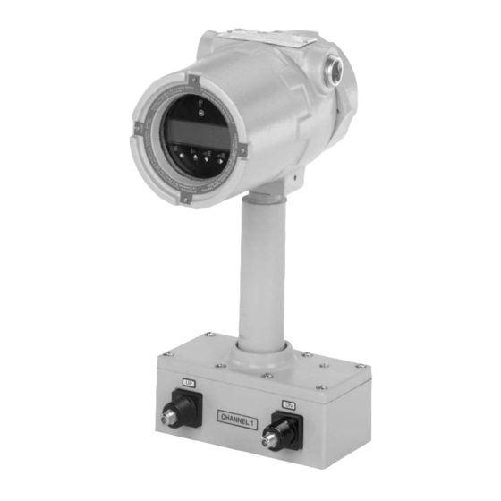
Description 3.3 Applications The SITRANS FUH1010 NEMA 7 model numbers: ● Single Path - 7ME3603-0 ● Dual Path - 7ME3603-3 (Wall Mount with display window) WARNING Electrical Shock Hazard Access to the Graphic display and keypad setup must be done with cover opened exposing high voltage connections. -
Page 25: Theory Of Operation
Description 3.4 Theory of Operation ● Finished Hydrocarbon Products ● Fuel Oil ● Bunker Fuel Typical Industries Serviced ● HVAC (Hotels, Airports, Government) ● Power Generation (Nuclear, Fossil, and Hydro) ● Chemical Processing ● Food and Pharmaceutical ● Aircraft Avionics and Ground Support ●... - Page 26 Description 3.4 Theory of Operation ① Velocity of Sound ② Flow Vector ③ Pipe ID ④ WideBeam Sensors ∅= sin (VOS / V Where: VOS = Velocity of sound in liquid phase = Phase velocity of sensor phase = 2 * ID / (VOS * cos ∅) ID = Pipe inside diameter = Transit time in liquid * DT / (2 * TL)
- Page 27 Description 3.4 Theory of Operation ① Fluid velocity near the axis of the flow stream tends to be greater. The Reynolds number is then computed as follows: where: viscosity = cS = cP/density Pipe ID = inches = inches/sec cS = kinematic viscosity cP = absolute viscosity The flow meter then uses this computation of Reynolds number to compensate the raw flow velocity for conditions of laminar or turbulent flow profile as defined by an internal Reynolds...
- Page 28 Description 3.4 Theory of Operation Viscosity Compensation Wide Beam technology is designed to utilize the resonant frequency of the pipe wall. It does so by broadcasting signals with various frequencies with the aim of finding the frequency that best matches the pipe wall. When found, the signal is transmitted into the flowing media with the wall of the pipe acting as a waveguide.
- Page 29 Description 3.4 Theory of Operation 2-Path 2-Path flow meters use two measurement channels to achieve a single output via a "virtual" third channel. The resultant data is the average of the two channels. Only clamp-on or in-line transit-time operation is allowed. Benefits include highest available precision and enhanced immunity to distorted flow profile conditions.
- Page 30 Description 3.4 Theory of Operation Flow Calibration Factor Normally, the flow stream is parallel to the axis of the pipe. On this basis, the calibration factor of a clamp-on ultrasonic flow meter is proportional to the cosine of the beam angle relative to the pipe axis.
- Page 31 Description 3.4 Theory of Operation FUH1010 IP65 NEMA 4X Precision Volume Operating Instructions, 01/2013, A5E32122003-AA...
-
Page 32: Installing/Mounting
Installing/mounting Installation safety precautions WARNING High pressure hazard In applications with working pressures/media that can be dangerous to people, surroundings, equipment or others in case of pipe fracture, we recommend that special precautions such as special placement, shielding or installation of a pressure guard or a safety valve are taken when the flowmeter is mounted. -
Page 33: Application Guidelines
Installing/mounting 4.3 Application Guidelines Application Guidelines Basic Requirements ● Determine pipe material and dimensions. ● Avoid vertical pipes flowing in a downward direction. ● Avoid installation of sensors on the top and bottom of horizontal pipes, if possible. ● Pipe surface should be smooth and, if necessary, free of paint. ●... -
Page 34: Figure 4-1 Pipe Mounting And Mounting Locations For Transmitter
Installing/mounting 4.4 Mounting the Transmitter ① ④ 2-in (6cm) pipe Cable Entry Ports ② ⑤ Transmitter Mounting Flange (also use for wall mounting) ③ ⑥ Mounting Plate U-Bolt Assembly for standard 2-in (6 cm) mounting pipe Figure 4-1 Pipe Mounting and Mounting Locations for Transmitter Note Use conduit fittings or cable glands on all cables. - Page 35 Installing/mounting 4.4 Mounting the Transmitter FUH1010 IP65 NEMA 4X Precision Volume Operating Instructions, 01/2013, A5E32122003-AA...
-
Page 36: Connecting
Connecting Safety notes for connecting Use in hazardous locations DANGER Explosion Hazard Death or severe personal injury and/or equipment and property damage will result if proper Hazardous (Classified) Locations installation precautions are not taken. Restrict use and repair to qualified personnel. Only qualified personnel may carry out work on the electrical connections. - Page 37 Connecting 5.1 Safety notes for connecting DANGER Explosion Hazard "Flameproof enclosure" type of protection Only open devices with type of protection "Flameproof enclosure" (e.g. FUT1010 NEMA 7) in hazardous areas when the power to the device is turned off, otherwise there is a risk of explosion.
-
Page 38: Transmitter Wiring
Connecting 5.2 Transmitter Wiring WARNING Electrical Voltage Hazard Incorrect device connections may result in death or severe personal injury and/or equipment and property damage. Only commission the device after the device has been properly connected and, if required, closed. Transmitter Wiring 5.2.1 Connecting Power DANGER... -
Page 39: Figure 5-1 Input Power (J10) Wiring
Connecting 5.2 Transmitter Wiring ① ⑥ Power Supply Wire Entry ② ⑦ Power Supply Access Cover Strip length 8mm (0.31 in) ③ ⑧ Fuse F1 Wire Clamp Screws ④ ⑨ Input Power Conn. J10 Ferrite power cord ⑤ Connector mounting screws Figure 5-1 Input Power (J10) Wiring 4. -
Page 40: Wiring Temperature Sensor To Transmitter
Connecting 5.2 Transmitter Wiring 7. Plug input power plug into connector J10 and secure using two captive connector mounting screws. 8. Replace access cover. Make sure Keypad Enable switch is in the "Enable" position (see below). ① Keypad Enable Switch 5.2.2 Wiring Temperature Sensor to Transmitter Wiring Temperature Sensor to the Analog Input ModuleSensor... -
Page 41: Figure 5-2 Analog Input Module Access
Connecting 5.2 Transmitter Wiring 3. Loosen the captive thumbscrew securing the Access Cover and remove Access Cover. 4. Using a flat-blade screwdriver, remove four captive screws securing the I/O board. Remove board and set it aside. ① ④ Access Cover Screw Latch ②... -
Page 42: Figure 5-3 Single Channel Temperature Sensor Inputs
Connecting 5.2 Transmitter Wiring ① ⑥ Black Short Terminals 1 and 4 (For FUE1010 - TB2 is used for another Temperature sensor.) ② ⑦ Orange Ground Terminals 2 and 3 to Terminal 5 ③ ⑧ Brown To Sensor ④ ⑨ 7ME39600CR (992EC) Series Cable ⑤... - Page 43 Connecting 5.2 Transmitter Wiring Wiring Temperature Sensor Board 1. Using a flat-blade screwdriver, loosen Terminal Block TB1 and TB2 screws. 2. Wire the RTD liquid 992EC temperature cable as shown in the table below: 992EC Series Cable Terminal TB1 Wire #1 (Black) To TB1--1 Wire #2 (Orange) To TB1--2...
-
Page 44: Sensor Wiring
Connecting 5.3 Sensor Wiring Note If analog input is used for temperature, this will take priority over clamp-on RTD measurement. NOTICE Power Supply Damage Improper power connections will damage power supply. Ensure that all AC or DC power supply connections are properly connected to the appropriate power source (100-250 VAC @ 50/60 Hz or 9-36 VDC). -
Page 45: Figure 5-4 Sensor Cable Connections
4. Apply power. 5. Within 10 seconds of power-up the transmitter main display will become active and a typical Siemens graphic will appear. The screen also identifies the software version of the unit as shown below. FUH1010 IP65 NEMA 4X Precision Volume... -
Page 46: Navigating The Menu
Connecting 5.4 Navigating the Menu Figure 5-5 Software Version (xx.xx.xx) 6. Press the <MENU> key and the Main Menu will appear. (Language selection is not on Version 3 op systems.) Navigating the Menu Installation Menu Navigation 7 8 9 MENU ENTER 4 5 6 HELP... -
Page 47: Programming The Transmitter
Connecting 5.5 Programming the Transmitter Table 5- 1 Keypad Function Chart Keys Description MENU Press to activate the Installation Menu. ENTER Store numeric data, select from option lists, etc. Left / Right Arrows Menu navigation keys move cursor. Use <Left Arrow> key to return to previous menus. Up / Down Arrows Same as <Left>... - Page 48 Connecting 5.5 Programming the Transmitter Create a Site (Required Entry) 1. At the [Channel Setup] menu press the <Right Arrow>. Note Before proceeding make sure that English or Metric units have been selected. 2. Press <Down Arrow> to select the [Create/Name Site] menu and enter a Site name. 3.
- Page 49 Connecting 5.5 Programming the Transmitter Select Pipe Class Pipe Class is a pre-loaded set of default pipe sizes for various ASA and metric pipes. If the intended pipe is standard the user may select this function to pre-load necessary pipe data, otherwise enter data manually using [Pipe O.D.], [Pipe Material] and [Wall Thickness].
-
Page 50: Figure 5-10 Sensor Installation
Connecting 5.5 Programming the Transmitter 4. Press <ENTER> to save selection. ① Select from list. 5. Press the <Left Arrow> and return to the main menu. Save/Rename Site Procedure 1. To save all programmed data to site, return to [Channel Setup] menu. 2. -
Page 51: Sensor Installation
Connecting 5.6 Sensor Installation Sensor Installation 5.6.1 Preliminary Installation Procedures Reflect and Direct Sensor Mounting Reflect and Direct mounting modes are supported for clamp-on sensors. The transmitter recommends a mounting mode after analyzing your pipe and liquid data entries. 1. After receiving the spacing index from the Installation Menu, prepare the pipe surface area where the sensors will be mounted. -
Page 52: Figure 5-7 Pipe Surface Preparation
Connecting 5.6 Sensor Installation Selecting a location for the sensors 1. The pipe at the mounting location must remain full, even at zero flow to maintain operation. 2. For the purposes of this device any location of straight pipe long enough to physically mount the sensors is adequate. -
Page 53: Sensor Identification And Selection
Connecting 5.6 Sensor Installation Direct mount provides a shorter sonic beam path. This usually improves signal with sonically attenuative liquids or pipe materials. Direct mount is recommended for plastic pipes. Compared to Direct mounting, Reflect mount requires almost double the amount of mounting length. -
Page 54: Figure 5-8 Universal Sensor Label
Connecting 5.6 Sensor Installation Typical Sensor Labels ① Universal Sensor model number ② Sensor size Figure 5-8 Sample Universal Sensor Label FUH1010 IP65 NEMA 4X Precision Volume Operating Instructions, 01/2013, A5E32122003-AA... -
Page 55: Figure 5-9 Hi Precision Sensor Label
Connecting 5.6 Sensor Installation ① Hi Precision sensor model number ② Sensor size Figure 5-9 Sample Hi Precision Sensor Label Sensor Selection The following is a typical sensor selection procedure. Note The transmitter must be powered up before you can select a sensor model. Refer to Transmitter Wiring (Page 37). - Page 56 Connecting 5.6 Sensor Installation 5. The drop down menu lists the following sensor selections: – 1011 Universal – 1011HP-T1 - Usable -40 to 120°C, recommended for Ø Temperature <40°C; Standard. – 1011HP-T2 - Usable -40 to 120°C, recommended for Ø Temperature >40°C - <80°C; Named as high temperature.
-
Page 57: Reflect Mount
Connecting 5.6 Sensor Installation 5.6.3 Reflect Mount Mounting Frame Installation 1. On a flat surface, attach the Spacer Bar to a Mounting Frame so that the Reference Hole on the Spacer Bar fits over the metal post on the platform of the frame. Tighten the clamping screw. - Page 58 Connecting 5.6 Sensor Installation ① ⑥ Front View Pipe ② ⑦ Spring Clip (Not present on some Mounting Strap Note: Optional 2nd models) Mounting Strap shown. Larger pipes over 76cm (30 inches) may need an additional support. ③ ⑧ Sensor Clamping Screw Spacer Bar Platform and Clamping Screw ④...
-
Page 59: Direct Mount
Connecting 5.6 Sensor Installation Installing the Sensor 1. Take either sensor and apply a continuous lengthwise 3mm (1/8-inch) bead of coupling compound across the center of the sensor emitting surface. ① ④ Coupling Compound Sensor ② ⑤ Emitting Surface Angled Edge ③... -
Page 60: Figure 5-12 Mylar Spacing Guide
Connecting 5.6 Sensor Installation Spacing Guide Sizes Metric English 5.08cm x 66.04cm 2" x 26" 5.08cm x 114.3cm 2" x 45" 10.16cm x 393.7cm 4" x 155" 15.2cm x 497.8cm 6" x 196" Figure 5-12 Mylar Spacing Guide 1. After receiving the spacing index from the Installation Menu, prepare the pipe surface area where the sensors will be mounted. -
Page 61: Figure 5-13 Wrap Strap Under Pipe And Attach To Adjusting Screw
Connecting 5.6 Sensor Installation ① ③ Sensor Clamping Screw Mounting Strap ② ④ Spring Clip Mounting Strap Adjusting Screw Figure 5-13 Wrap Strap Under Pipe and Attach to Adjusting Screw 7. Slide the mounting strap over it (and under the clip if there is one) and tighten with a screwdriver. -
Page 62: Figure 5-14 Wrapping The Mylar Spacing Guide Around The Pipe (End View)
Connecting 5.6 Sensor Installation ① ⑤ Sensor 1 Sensor Edge Line ② ⑥ Pipe Spacer Bar ③ ⑦ ④ ⑧ Sensor 2 Line ⑨ Mylar Spacing Guide 10. Disassemble the spacer bar and the unmounted frame. Use the bar as a straight edge and, with one edge against the mounted frames tapered roller center and the other crossing the dot you drew, draw a line crossing the dot (see "B"... -
Page 63: Figure 5-15 Finding The Halfway Distance
Connecting 5.6 Sensor Installation 11. Wrap the Mylar spacing guide around the pipe so that the left edge is against the sensor edge mark (see "C" above). Arrange so that one end overlaps the other by at least three inches. Trim to fit if necessary, but be sure not to trim at the overlapping end in order to keep it square. -
Page 64: 1012T Mounting Tracks
Connecting 5.6 Sensor Installation 16. Prepare the area you marked by de-greasing the surface, if needed, and removing any grit, corrosion, rust, loose paint or surface irregularities with the abrasive pipe conditioning material provided. Clean the pipe of any debris and abrasive particles. 17. - Page 65 Connecting 5.6 Sensor Installation Installing a 1012T Mounting Track in Reflect Mode The sensor installation procedures show how the automatic selection of sensors, mounting mode and spacing method are established. Examine the figure below, which illustrates a typical [Install Sensor] menu screen. Note the automatic assignment of mounting track part number, plus the designation of the number index.
-
Page 66: Figure 5-17 Reflect Mount With Model 1012Tn Mounting Track (Side View)
Connecting 5.6 Sensor Installation 1. Perform all required menu steps up until the point where you respond to the [Install Complete] prompt. 2. Make note of the Number Index. Check to ensure that you have a matched set of sensors. They both should have the same serial number but marked with either an "A" or "B"... - Page 67 Connecting 5.6 Sensor Installation 5. Rotate the track rail assembly to the intended mounting position on the pipe, then tighten both tension screws just enough to prevent rotation. Do not over tighten. 6. Prepare the sensor location by degreasing the surface, if needed, and removing any grit, corrosion, rust, loose paint or surface irregularities with the abrasive pipe conditioning material provided.
-
Page 68: Figure 5-18 Direct Mount 180° Opposed With Mounting Tracks
Connecting 5.6 Sensor Installation ● Direct Mode Track Assembly - This track rail has number index holes for inserting an index pin to position the other sensor. Note Index pins are used as stops against each sensor at the reference hole for one sensor, ⑨... - Page 69 Connecting 5.6 Sensor Installation 1. Perform all required menu programming steps up until the point where you respond to the [Install Complete] prompt. 2. Make a note of the reported Number Index displayed in the [Install Sensor] menu. Check to ensure that you have a matched set of sensors. They both should have the same serial number but marked with either an "A"...
-
Page 70: Figure 5-19 Track Rail Alignment
Connecting 5.6 Sensor Installation ① Align tracks with Spacer Guide edge ② Mylar Spacer Guide ③ Halfway distance of Spacer Guide Figure 5-19 Track Rail Alignment FUH1010 IP65 NEMA 4X Precision Volume Operating Instructions, 01/2013, A5E32122003-AA... -
Page 71: Figure 5-20 Ref And Number Index Pin Locations
Connecting 5.6 Sensor Installation Sensor Installation 1. Insert an index pin into the REF hole of the track marked "Reflect Mode Spacing." 2. Take one sensor and apply a 3mm (1/8-inch) continuous bead of couplant compound along the center of the contact surface of the sensor. Insert it between the track rails and to the left of the index pin with the cable connector pointing away from the pin. -
Page 72: Mounting Temperature Sensors
Connecting 5.7 Mounting Temperature Sensors 7. Observing the upstream and downstream orientation, attach the UP (upstream) and DN (downstream) cables to the sensors and make snug. Attach the other ends to the UP and DN terminals of the transmitter. 8. Proceed to Commissioning (Page 73). Mounting Temperature Sensors Temperature is used to normalize the liquids sonic velocity in order to properly determine interfaces and for density determination. - Page 73 Connecting 5.7 Mounting Temperature Sensors Clamp-on style sensors are mounted on the surface of the monitored pipe using series mounting assemblies. Apply a generous quantity of thermal couplant (provided) to the tip of the sensor and attach it securely to the cleaned pipe surface with the proper mounting assembly.
-
Page 74: Commissioning
Commissioning General requirements Before commissioning it must be checked that: ● The device has been installed and connected in accordance with the guidelines provided in chapter 4 "Installing/mounting (Page 31)" and chapter 5 "Connecting (Page 35)" ● Device installed in hazardous location meets the requirements described in "Installation in hazardous location (Page 13)"... - Page 75 Commissioning 6.2 Commissioning 3. The meter will go through the drives. 4. Observe the Measured Vs window and verify a correct sound velocity measurement (if known). 5. Press the <Down Arrow> to accept sound velocity value. 6. Press the <Right Arrow> and then <ENTER> to save the site data. 7.
-
Page 76: Empty Pipe Set
Commissioning 6.3 Empty Pipe Set See also Refer to I/O Connections and Wiring (Page 163) for input/output wiring and Span Data (Page 94) for data spanning procedures. Empty Pipe Set The flow meter performs the MTYmatic routine automatically during its Initial Make-up to establish a standard setting for the Empty Pipe alarm. - Page 77 Commissioning 6.3 Empty Pipe Set 4. Empty the pipe completely, then press <ENTER>. – Fill Pipe Press [ENT] appears on the menu prompt line. Figure 6-1 Empty Pipe Set 5. Refill the pipe completely, then press <ENTER>. Using the MTYmatic command You can repeat MTYmatic (performed during the Initial Makeup) to correct an inaccurate Actual MTY setting if conditions do not allow you to repeat the Actual Empty procedure.
- Page 78 Commissioning 6.3 Empty Pipe Set To start MTYmatic: 1. From [Channel Setup] scroll down to [Install Sensor]. 2. Press the <Right Arrow> to access the [Empty Pipe Set] option list. 3. Move the cursor next to [MTYmatic] press the <Right Arrow>. 4.
-
Page 79: Installation Menus
Commissioning 6.4 Installation Menus 4. Press <ENTER>. The current empty threshold number appears in a pop-up window. 5. Use the numeric keys to type a new Set Empty number. 6. To store the Set Empty number press <ENTER> Installation Menus FUH1010 Precision Volume Installation Menu Chart Use <Left>, <Right>, <Up>... - Page 80 Commissioning 6.4 Installation Menus Level A Level B Level C Level D (see Level E Level F manual) Mod of Elast PSI Numeric Entry Application Data Liquid Class Select Liquid Enter From List Estimated Vs M/S Numeric Entry Viscosity <cS> Numeric Entry Liquid Table Enter From List...
- Page 81 Commissioning 6.4 Installation Menus Level A Level B Level C Level D (see Level E Level F manual) Table Active 1 No/Yes- Clear Table 1 No/Yes Calib. Table 2 Same as Table 1 Calib. Table 3 Same as Table 1 Display Setup Select Data Enter From List...
- Page 82 Commissioning 6.4 Installation Menus Level A Level B Level C Level D (see Level E Level F manual) Analog Out Trim Io1 Operate / Trim @ Trim Trim Io2 Operate / Trim @ Trim Vo1 Operate / Trim @ Trim Vo2 Operate / Trim @ Trim Pgen1 Operate / Trim @...
- Page 83 Commissioning 6.4 Installation Menus ① ⑤ Menu Cell Data (left-hand column) Current Selected Measurement Channel ② ⑥ Highlighted Menu Cell Site Name Identified ③ ⑦ Menu Prompt Line (Reverse Video) Highlighted Data ④ ⑧ Current Selected Meter Type Menu Cell Data (right-hand column) Figure 6-2 Typical Installation Menu Screen FUH1010 IP65 NEMA 4X Precision Volume...
-
Page 84: Functions
Functions Setting Liquid Parameters Introduction The flow meter measures and reports the flowing liquid’s sonic velocity (Vs) and its temperature (T). These components create the liquid’s "Vs/T" signature. This signature is a fundamental component of the LiquIdent routine that identifies positively any liquid monitored by the flow meter. - Page 85 Functions 7.1 Setting Liquid Parameters To enter the LiquIdent Slope Factor: 1. From the [Chan/Path Setup] menu scroll down to the [Application Data] menu and press the <Right Arrow> to highlight [Liquid Class]. 2. From [Liquid Class] press <Up/Down Arrow> to scroll down to [Liquid Table]. 3.
- Page 86 Functions 7.1 Setting Liquid Parameters Setting the Pressure Slope The flow meter measures and reports the flowing liquid’s sonic velocity (Vs) and its related pressure (P). Since a pressure change will affect the sonic velocity of the liquid, a method to balance the measured sonic velocity to a fixed reference temperature (15.6ºC/60ºF) default) is provided.
-
Page 87: Table 7- 1 Common Liquid Classes
Functions 7.1 Setting Liquid Parameters Note Altering the Base Temperature will result in all "Base" outputs and settable items to be referenced to the selected temperature. Entering K0 and K1 parameters (API thermal expansion coefficients): The K0 and K1 parameters represent the thermal expansion coefficients for the Liquid Class. The meter requires these parameters to apply the proper volume correction. - Page 88 Functions 7.1 Setting Liquid Parameters Entering the K0 and K1 thermal expansion coefficients: 1. From the [Application Data] menu press <Right Arrow> to highlight [Liquid Class] menu. 2. Scroll down to [Liquid Table] menu cell and press <Right Arrow>. 3. Press <Up/Down Arrow> to scroll down to [K0]. 4.
- Page 89 Functions 7.1 Setting Liquid Parameters 5. Use the keypad numeric keys to enter the desired LiquIdent Index Value. 6. To enter the LiquIdent Index Value press <ENTER>. Each of the data points of a Site Liquid Table (maximum of 32) may be filled in by the user as indicated in the menu screen shown above.
-
Page 90: Selecting Flow Units
Functions 7.2 Selecting Flow Units Liquid Name You may install a name here if you wish to identify the liquid in the meter's datalogger report. To prevent flicker of two names when the LiquIdent is at transition points, you may wish to create ranges of LiquIdent and additional entries in between with no name installed. -
Page 91: Table 7- 3 Totalizer Modes
Functions 7.2 Selecting Flow Units 4. Scroll down to the [Flow/Total Units] menu and press the <Right Arrow> to select the [Flow Vol. Units] menu. 5. Press the <Right Arrow> to select the option list and use the <Up/Down Arrows> to select the desired units. - Page 92 Functions 7.2 Selecting Flow Units Note NETFLOW (default) is best for applications where there may be zero flow for long periods. It minimizes false Totalizer register increments due to data scatter. Press the <Down Arrow> to accept the default setting. Selecting Totalizer modes 1.
- Page 93 Functions 7.2 Selecting Flow Units Communications Setup Connect the flow meter to your PC. Refer to Appendix A for programming and communicating, if needed. 1. Access Si-Ware or, if using a PC, access HyperTerminal from the PC [Programs] menu, then select [HyperTerminal]. 2.
-
Page 94: Table 7- 4 Totalizer Controls (The "N" In
Functions 7.2 Selecting Flow Units Table 7- 4 Totalizer Controls (the "n" in <Fn> = channel number)* PC # Command Description CLRTOT Resetting the Totalizer registers clears all total data accumulated during operation. (also clears Note: In Dual Path mode, the Totalizer operates only on the virtual system channel overflow) (Ch 3).= Channel Number) -
Page 95: Span Data
Functions 7.3 Span Data Span Data The [Span Data] menu allows you to set 0% and 100% output limits for volumetric flow (Vfo), absolute flow (Vfab) and sonic velocity (Vs). Each menu cell shows appropriate rate units and time base. If you change flow rate units after spanning the system, the computer automatically updates the output data setup to reflect the change. - Page 96 Functions 7.3 Span Data 4. Highlight [Span Data] and press the <Right Arrow>. 5. Highlight [Max Flow] and press <Right Arrow> to. Input 100% flow rate numeric data for 20mA. Press <ENTER> to store data. 6. Scroll down to [Min Flow].Press <Right Arrow> to input 0% flow rate numeric data for 4mA.
-
Page 97: Table 7- 5 Input/Output Wiring (Tb2) - 7Me39400Al03 Expanded I/O Module
Functions 7.3 Span Data Table 7- 5 Input/Output Wiring (TB2) - 7ME39400AL03 Expanded I/O Module Pin# Signal Definition Description Function Dual/Quad Path Only POS [+] Total TTL 0-5000 Hz frequency output , POS [+] Total TTL assignable POS [+] Total OC POS [+] Total OC NEG [-] Total TTL) NEG [-] Total TTL... -
Page 98: Table 7- 6 Open Collector User Resistor Recommendations
Functions 7.3 Span Data Table 7- 6 Open Collector User Resistor Recommendations User Supply External Resistor Expected Recommended Resistor Wattage (Watts) Voltage (VDC) (Ohms) Current Draw (mA) 18.5 17.6 17.6 1000 1500 1800 15.5 1 1/4 2400 1 1/4 To change the default PGEN settings: 1. - Page 99 Functions 7.3 Span Data Adjusting the PGEN Output The default setting for the Digital PGEN output provides a 5000 Hz frequency at an assumed maximum velocity of 100 ft/sec. In certain cases it may be necessary to change this default PGEN value.
-
Page 100: Analog Out Setup
Functions 7.4 Analog Out Setup Analog Out Setup The flow meter provides current, voltage and pulse-rate analog outputs. The [Analog Out Setup] menu allows you to assign data functions for these signals. The transmitter terminal strip contains the analog output terminals. Table 7- 7 Analog Outputs Io (Isolated Current) - Page 101 Functions 7.4 Analog Out Setup Assigning a function to the current output: 1. From the [Chan/Path Setup] menu scroll to [I/O Data Control]. 2. Press <Right Arrow] to highlight the [Analog Out Setup] menu. 3. Press <Right Arrow> twice to access the [Io] option list. 4.
-
Page 102: Analog Input Setup
Functions 7.5 Analog Input Setup Assigning a function to the voltage output: 1. From the [Analog Out Setup] menu, press <Right Arrow> to access the [Vo1] option list. 2. Move the cursor to the desired data function by pressing <Up/Down Arrow>. 3. - Page 103 Functions 7.5 Analog Input Setup The flow meter recognizes the first analog input variable that is assigned to any given parameter and ignores any subsequent input with the same assignment. For example, if Iin1 and Iin2 are both assigned to represent pressure (PSIA), the flow meter will only use the pressure input from Iin1.
- Page 104 Functions 7.5 Analog Input Setup 1. Access the [Iin1] option list by pressing the <Right Arrow> twice. 2. Move the cursor down to [Aux] by pressing the <Down Arrow> and then press <ENTER>. This enables the port to receive an input current. The cursor moves to [4 mA]. 3.
-
Page 105: Expanded I/O Option
Functions 7.6 Expanded I/O Option Expanded I/O Option Note For SITRANS F 1010 systems equipped with 1010N-7 Expanded I/O Module only. The 1010N-2 I/O Module and 1010N-7 Expanded I/O Module both provide current (Io1, Io2), voltage (Vo1 and Vo2) and pulse rate (Pgen 1 and Pgen 2) analog outputs. The Expanded I/O Module Option allows users to drive as many as four additional 4-20mA loop-powered instrumentation outputs. - Page 106 Functions 7.6 Expanded I/O Option Expanded I/O Module Option The Expanded I/O Module Option provides expanded Io analog outputs. It is implemented through the use of a 1010N-7 Expanded I/O Module occupying the same position as the 1010N-2 I/O Module. This option allows users to drive up to four additional 4-20mA loop- powered instrumentation outputs.
-
Page 107: Table 7- 10 Typical 2-Channel Flow Meter Expanded I/O Option Connections
Functions 7.6 Expanded I/O Option 1010N-7 Expanded I/O Module Option The Expanded I/O Module Option provides all of the above plus the following outputs: ● The four signals that drive the pulse generator outputs (Pgen1 and Pgen2) and voltage outputs (Vo1 and Vo2) of the flow meter create four current outputs: Aux Io1, Aux Io2, Aux Io3 and Aux Io4 (see diagram). - Page 108 Functions 7.6 Expanded I/O Option Expanded I/O Module Option Programming The diagram below illustrates the Expanded I/O Module Option programming for a Single Channel flow meter with a 1010N-7 Expanded I/O Module. ① Flow meter Internal Connections ② Output Terminal Strip Note The 1010N-7 Expanded I/O Module auxiliary output signals (Aux Io1 - Aux Io4) generated from Pgen1, Pgen2, Vo1 and Vo2 are "mirrored"...
-
Page 109: Logger Control
Functions 7.7 Logger Control Logger Control Logger Control Menu The Logger Control menu in the [Meter Facilities] menu provides the Logger controls for the flow meter measurement channels and paths. It allows the user to select data items/alarm events, a logging interval and a destination for Logger reports. While the Logger Setup menu is measurement channel/path specific, this Logger Control menu provides global control functions. - Page 110 Functions 7.7 Logger Control Display Logger This menu cell allows you to send the Logger contents to the display screen. This command is effective only after a successful install. You can set the report to scroll on the screen with or without line-wrap.
- Page 111 Functions 7.7 Logger Control 4. To transmit Logger contents to external device via the serial port press <ENTER>. 5. To stop printout press <Left Arrow>. Circular Memory In its default mode, the Logger collects data until its memory becomes full. At that time the flow meter suspends datalogging and cannot resume until the Logger memory is cleared (see Clear Logger command).
-
Page 112: Setting Thermal Coefficient And Modulus Of Elasticity
Functions 7.8 Setting Thermal Coefficient and Modulus of Elasticity Clearing Logger Memory 1. To access the [Clear Logger] option list press <Right Arrow>. 2. Move the cursor to [Yes] by pressing <Up/Down Arrow>. 3. To clear the memory press <ENTER>. Setting Thermal Coefficient and Modulus of Elasticity Introduction This operating system includes routines that will compensate the measured raw flow rate for... - Page 113 Functions 7.8 Setting Thermal Coefficient and Modulus of Elasticity The default value for each of these new parameters is 0.0. A value of zero effectively disables the pressure and temperature pipe volume compensation routine. When entering a value for the thermal expansion coefficient and modulus of elasticity, keep in mind that the numeric entry already includes an exponent multiplier.
-
Page 114: Operation Adjust Menu Settings
Functions 7.9 Operation Adjust Menu Settings Operation Adjust Menu Settings Introduction The [Operation Adjust] menu becomes available after picking a meter type and measurement channel. It is recommended that you use it after the sensors are installed and operating to "fine-tune" the meter’s output characteristics. Each application presents different data display and output requirements due to unique pipe and liquid conditions. - Page 115 Functions 7.9 Operation Adjust Menu Settings Setting SmartSlew: 1. From the [Dual Path Flow] menu scroll to the [Operation Adjust] menu and press <Right Arrow>. 2. At the [Damping Control] menu press the <Right Arrow> and move the cursor down to [SmartSlew].
-
Page 116: Setting Relays
Functions 7.10 Setting Relays 3. Move the cursor down to [Memory] by pressing <Up/Down Arrow>. 4. To make selection press <ENTER>. 5. This moves the highlight to [Memory Delay <s>]. Memory Delay (s) Selecting [Memory Delay <s>] activates the suppressed [Memory Delay] menu cell. It allows you to specify the number of seconds that the flow meter maintains its last valid flow reading. -
Page 117: Table 7- 12 Relay Option List
Functions 7.10 Setting Relays Relay 1, 2, 3, and 4 Function Assignments The flow meter, depending upon the model, provides four alarm relays. Please refer to the Appendix A (Page 163) for wiring details. Relays respond to any of the alarm conditions or data functions included on the Relay Option List. - Page 118 Functions 7.10 Setting Relays Assigning functions to Relay 1: 1. From the [Dual Path Flow] menu scroll down and highlight [I/O Data Control]. 2. Press <Right Arrow> and scroll down to [Relay Setup]. 3. To access the [Relay Setup] option list press <Right Arrow>. 4.
-
Page 119: Memory Control
Functions 7.11 Memory Control 7.11 Memory Control Introduction Memory Control is a reference menu that shows the amount of bytes of data memory left. The data memory capacity depends on the number and complexity of the site setups stored in memory and the size of the current Datalogger file. The [Memory Control] menu is located in the [Meter Facilities] menu. -
Page 120: Analog Output Trim
Functions 7.12 Analog Output Trim 7.12 Analog Output Trim Introduction Analog Out Trim function allows you to fine-tune the flow meter’s analog voltage and current outputs using an ammeter connected to the output under test. In addition, you can use a frequency counter to fine-tune the flow meter’s pulse rate output. - Page 121 Functions 7.12 Analog Output Trim Current Output Trim (Io1 & Io2) Note Can be trimmed to within .005mA of nominal. To calculate a current output: 1. Set up an ammeter to read Amps, then connect it to the supply and return terminals of the current output under test.
- Page 122 Functions 7.12 Analog Output Trim Voltage Output Trim (Vo1 & Vo2) Note Can be trimmed to within .0025 V of nominal. To calculate a voltage output: 1. Set up a multimeter to read volts, then connect it to the supply and return terminals of the voltage output under test.
-
Page 123: Resistive Temperature Device (Rtd) Calibration
The [RTD Calibrate] menu appears on all SITRANS 1010 models. Use this menu to calibrate Temperature Sensors to an external standard. It is important to note that Siemens RTD temperature sensors are factory-calibrated for high accuracy. We recommend that before deciding to perform the calibration, check the current RTD reading in the [Diagnostics Data] menu. - Page 124 Functions 7.13 Resistive Temperature Device (RTD) Calibration To enter the current RTD temperature: 1. From the [RTD Calibrate] menu press <Right Arrow> to access the RTD option list. 2. Press <Right Arrow> to highlight the RTD you want to calibrate (RTD 1 or RTD 2). 3.
- Page 125 Ice Bath RTD Calibration Use deionized water and ice mixture at 0°C (32°F) equilibrium for an ice bath. Ensure temperature with a reference thermometer. Siemens can not assume responsibility for the incorrect design, construction or operation of an Ice Bath.
-
Page 126: Sonilocator Operation
SONILOCATOR Operation Introduction Note The Sonilocator function can only be invoked while flow meter is used as part of a Siemens Leak Detection System. In the event of a pipeline leak, a sudden drop in pressure occurs radiating a pressure wave both upstream and downstream from that point at the speed of sound in the liquid. - Page 127 Functions 7.14 SONILOCATOR Operation 4. Press the <Right Arrow> key and then the <Up/Down> key to scroll to the desired Slew Rate resolution. Press the <ENTER> key to select it. 5. Verify [SL Rate] resolution is selected (> symbol will appear to the left of menu item). SL Rate choices include: 20 ms, 50 ms, 100 ms, 250 ms (20 ms highest resolution;...
- Page 128 Functions 7.14 SONILOCATOR Operation 5. Press the <Up/Down Arrow> key and scroll to the [Sonilocate] menu item. Press the <ENTER> key to select it. (A + sign will appear to the left of the menu item.) If desired, press <CLR> key to deselect menu item. 6.
- Page 129 Functions 7.14 SONILOCATOR Operation FUH1010 IP65 NEMA 4X Precision Volume Operating Instructions, 01/2013, A5E32122003-AA...
-
Page 130: Alarm, Error And System Messages
Alarm, error and system messages Alarm Codes Alarm Codes and Descriptions The following alarm codes appear on the main display of the transmitter. Letter Codes Alarm Code Description SPACE Spacing Sensor spacing may need adjustment EMPTY Empty Pipe is empty HI/LO Rate Flow above High setting or below Low setting... -
Page 131: Alarms
Alarm, error and system messages 8.2 Alarms 68.10 112.38 30.0 -30.0 9/26 12:45 ① Alarm Codes Alarms Set Alarm Levels Menu The [Set Alarm Levels] menu allows you to select system alarm functions. Alarms appear locally on the LCD digital display. In addition, you can use the Relay Setup menu to assign those functions to the system’s relays. - Page 132 Alarm, error and system messages 8.2 Alarms Relay Hold Time The [Relay Hold Time] menu item allows the setting of the time in seconds that the alarm relay will stay closed. High LiquIdent Use the [High LiquIdent] menu item to set the numerical high limit span of the LiquIdent function.
- Page 133 Alarm, error and system messages 8.2 Alarms FUH1010 IP65 NEMA 4X Precision Volume Operating Instructions, 01/2013, A5E32122003-AA...
-
Page 134: Service And Maintenance
● Seal integrity of the process connections, cable entries, and cover screws ● Reliability of power supply, lightning protection, and grounds NOTICE Repair and service must be carried out by Siemens authorized personnel only. Note Siemens defines flow sensors as non-repairable products. -
Page 135: Transportation And Storage
● Information about field service, repairs, spare parts and lots more under "Services." Additional Support Please contact your local Siemens representative and offices if you have additional questions about the device. Find your local contact partner at: http://www.automation.siemens.com/partner See also Local contact person (http://www.automation.siemens.com/partner) -
Page 136: Repair
9.4 Repair Repair 9.4.1 Unit repair NOTICE Repair and service must be carried out by Siemens authorized personnel only. Note Siemens defines flow sensors as non-repairable products. WARNING Impermissible repair of explosion protected devices Danger of explosion in areas subject to explosion hazard. -
Page 137: Return And Disposal
Service and maintenance 9.5 Return and disposal Return and disposal WARNING Incorrect disassembly The following dangers may result through incorrect disassembly: - Injury through electric shock - Danger through emerging media when connected to the process - Danger of explosion in hazardous area In order to disassemble correctly, observe the following: ... -
Page 138: Battery Disposal
In accordance with EU directive 2006/66/EC, batteries are not to be disposed of using municipal waste disposal services. Waste industrial batteries are accepted back by Siemens or by the local Siemens representative. Please talk to your local Siemens contact (http://www.siemens.com/automation/service&support) or follow the return procedures (Page 136) of Siemens Flow Instruments. -
Page 139: Disposal
Service and maintenance 9.5 Return and disposal 9.5.3 Disposal Devices identified by this symbol may not be disposed of in the municipal waste disposal services under observance of the Directive 2002/96/EC on waste electronic and electrical equipment (WEEE). They can be returned to the supplier within the EC or to a locally approved disposal service. -
Page 140: Troubleshooting
The following is list of troubleshooting tips and messages that you may encounter. They include explanations and, in some cases, a recommended action. If a problem seems unsolvable, contact your local Siemens Ultrasonic Flow Representative for expert help at www.automation.siemens.com/partner (http://www.automation.siemens.com/partner). - Page 141 Call technical support for help, if necessary. Note If you receive a Detection Fault message, it is strongly recommended that the Technical Service Department (http://www.automation.siemens.com/partner) be contacted. FUH1010 IP65 NEMA 4X Precision Volume Operating Instructions, 01/2013, A5E32122003-AA...
-
Page 142: F4 Reset Procedure
Troubleshooting 10.2 F4 Reset Procedure 10.2 F4 Reset Procedure You may encounter an operating problem that blocks access to the Diagnostics Menu, or the flow meter may operate erratically after exposure to a power transient or some other traumatic event. These cases may require use of the F4-reset sequence to restore operation. -
Page 143: Test Facilities Graph Screen
Troubleshooting 10.3 Test Facilities Graph Screen 3. To access the F4 Reset option list press the <Right Arrow>. Press the <Down Arrow> to switch the option list to [Clr Saved Data? Yes]. NOTICE Loss of RAM Data Before proceeding further it is essential to understand that this function eliminates ALL data stored in RAM. - Page 144 Troubleshooting 10.3 Test Facilities Graph Screen Figure 10-1 Test Facilities Graph Screen Entering the Diagnostic Graph Screen Before you can view the Diagnostic Graph Screen the flow channel must first be properly installed and operating in a non-empty condition. If a previously installed channel is in a "Fault"...
- Page 145 Troubleshooting 10.3 Test Facilities Graph Screen Time Base Control The digitized receive signal can be moved either to the left or right on the screen by pressing the <Left> or <Right> keypad arrows. The direction of the arrow actually represents the direction in which the Receive "window"...
- Page 146 Troubleshooting 10.3 Test Facilities Graph Screen [MinDamp #] Command Pressing the <1> key will cause [MinDamp #] to appear on the command line at the lower left-hand corner of the screen. The number listed to the right of the command code represents the exponent in the meter exponential averaging routine, where the larger the number the greater the digital averaging.
-
Page 147: Figure 10-2 Setting Digital Damping Factor
Troubleshooting 10.3 Test Facilities Graph Screen To activate the Test Facilities Graph Screen: 1. In the main menu, scroll to the [Diagnostic Data] menu and select [Test Facilities]. 2. Scroll down to [Graph], press the <Right Arrow> and highlight [Yes]. Press <ENTER> to select. -
Page 148: Figure 10-3 Setting The Mindamp Factor
Troubleshooting 10.3 Test Facilities Graph Screen To INCREASE the Digital Damping: 1. Press the <1> key while viewing the Test Facilities Graph Screen as shown above. The damping control [MinDamp #] will appear on the command line at the lower left-hand corner of the screen. - Page 149 Troubleshooting 10.3 Test Facilities Graph Screen Transit Time Adjustment: (Hot Key 3) Observe the short vertical marker at the beginning of the receive signal in the Graph Screen above. This line represents the position in time (Tn) where the flow meter perceives the arrival of the ultrasonic signal.
- Page 150 Troubleshooting 10.3 Test Facilities Graph Screen Envelope Threshold Adjustment: (Hot Key 5 & 6) Pressing the <=> key causes the graph to toggle between the default signal waveform screen and the signal envelope screen (see example below). This envelope screen can aid in the diagnosis of Tn errors caused by unusual receive waveform distortion.
-
Page 151: Table 10- 2 Description Of Graph Screen Text Display Parameters
Troubleshooting 10.3 Test Facilities Graph Screen Signal Masking Function: (Hot Key 7) Under conditions of extremely low signal amplitude, a noise spike associated with the flow meter receive signal window may be present on the extreme left side of the graph display. If this spike is large enough it may interfere with the signal detection routines. -
Page 152: Table 10- 3 Hot Key Summary
Troubleshooting 10.3 Test Facilities Graph Screen Table 10- 3 Hot Key Summary Command Line Description <+> Expands (magnifies) waveform to view more detail. <-> Contracts waveform to view more of the waveform. <Left Arrow> Shifts receive window to the left (waveform to the right). -
Page 153: Site Setup Data
Troubleshooting 10.4 Site Setup Data 10.4 Site Setup Data This menu provides data pertaining to sensor characteristics and operation. Some menu items are for technical support interpretation only. Table 10- 4 Site Setup Menu Items fx Drive Current Transmit drive code selected during Initial Makeup. - Page 154 Troubleshooting 10.4 Site Setup Data [HF] Menu Item The flow meter includes a Diagnostics Menu item that permits the entry of a flow registration correction parameter labelled [HF]. This "HF" parameter is the input for a proprietary algorithm that automatically compensates for signal beam blowing, thereby extending the upper flow limit of the flow meter.
- Page 155 Troubleshooting 10.4 Site Setup Data Manual Adjustment Procedure 1. In the [Site Setup Data] Menu, press the <Down Arrow> and scroll to the [HF] menu cell. Press the <Right Arrow> and a pop-up [Manual] prompt will appear as shown below. Note Press the <Up/Down Arrow>...
- Page 156 Troubleshooting 10.4 Site Setup Data Automatic Adjustment Procedure 1. In the [Site Setup Data] Menu, press the <Down Arrow> and scroll to the [HF] menu cell. Press the <Right Arrow> and a pop-up [Manual] prompt will appear. 2. Press the <Up or Down Arrow> to select [Automatic] then press <ENTER>. 3.
- Page 157 Troubleshooting 10.4 Site Setup Data Note The value shown in the [Automatic] pop-up prompt can not be changed and is for user information only. 5. If you decide not to use the [Automatic] selection, press any key other than <ENTER> to abort the operation.
-
Page 158: Force Transmit
NOTICE Incorrect Diagnostic Procedures The Force Transmit and Force Frequency diagnostic procedures are preconfigured at the factory and should only be implemented by approved Siemens personnel otherwise damage to the equipment may occur. Restrict use and repair to qualified personnel. - Page 159 Troubleshooting 10.5 Force Transmit Setting a Force Transmit condition 1. After [Install] command is invoked and while the flow meter is going through the drive selections press the <ALT> and <MENU> keys simultaneously. Note The <ALT> and <MENU> keys must be pressed before the flow meter scans through all the drives, or the Force Transmit function must be initiated again.
- Page 160 Troubleshooting 10.5 Force Transmit Setting a Forced Frequency 1. To force a frequency, repeat steps 1 and 2 above, but press <Right Arrow>. The following typical display line will appear: Drive =0 2. Using numeric keys enter the frequency and press <ENTER>. 3.
- Page 161 Troubleshooting 10.5 Force Transmit FUH1010 IP65 NEMA 4X Precision Volume Operating Instructions, 01/2013, A5E32122003-AA...
-
Page 162: Technical Data
Technical Data Transmitter ● Operating Temperature Range: -18°C to 60°C (0°F to 140°F) ● Storage Temperature Range: -20°C to 93°C (-4°F to 200°F) Degree of Protection ● Wall mount enclosure: IP65 (NEMA 4X) ● Wall mount explosionproof: IP66 (NEMA 7) Input ●... - Page 163 Please note the following: ● The user is responsible for all changes and repairs made to the device. ● All new components must be provided by Siemens Industry, Inc. ● Restrict repair to faulty components only. ● Do not re-use faulty components.
-
Page 164: Ordering
In order to ensure that the ordering data you are using is not outdated, the latest ordering data is always available on the Internet: Catalog process instrumentation (http://www.siemens.com/processinstrumentation/catalogs) I/O Connections and Wiring Terminal Block Wiring - 7ME39400AL00 and 7ME39400AL01 I/O Module (Refer to manual drawing 1010N-2-7 sheet 2 of 2) These connection diagrams apply to the part numbers listed below. -
Page 165: Figure A-1 7Me39400Al00 And 7Me39400Al01 I/O Module
Appendix A A.2 I/O Connections and Wiring Figure A-1 7ME39400AL00 and 7ME39400AL01 I/O Module FUH1010 IP65 NEMA 4X Precision Volume Operating Instructions, 01/2013, A5E32122003-AA... -
Page 166: Table A- 2 Input/Output Wiring (Tb2) - 7Me39400Al00 And 7Me39400Al01 I/O Module
Appendix A A.2 I/O Connections and Wiring Table A- 2 Input/Output Wiring (TB2) - 7ME39400AL00 and 7ME39400AL01 I/O Module Pin# Signal Description Definition Function Vo1+ Meter process variables 0-10 Volt Analog Output System outputs assignable and scalable are assigned to individual to flow related parameters. -
Page 167: Table A- 3 Input/Output Wiring (Tb3) - 7Me39400Al00 And 7Me39400Al01 I/O Module
Appendix A A.2 I/O Connections and Wiring Table A- 3 Input/Output Wiring (TB3) - 7ME39400AL00 and 7ME39400AL01 I/O Module Pin# Signal Definition Description Function Function Function Function Single Dual Channel Dual Path Dual Path Channel Only K1 A Relay 1 Normally Open Relay 1 Alarm or Alarm or... - Page 168 Appendix A A.2 I/O Connections and Wiring K1-A *K1-B K1-C K2-A *K2-B K2-C K3-A *K3-B K3-C K4-A *K4-B K4-C Note Relays shown in Power OFF position, which is the same as the alarm assertion position. *7ME39400AL00 Mercury Relay only available with Normally Open. Terminal Block Wiring - 7ME39400AL03 and 7ME39400AL04 Expanded I/O Module (Refer to manual drawing 1010N-7-7 sheet 2 of 2) These connection diagrams apply to the part numbers listed below.
-
Page 169: Figure A-2 7Me39400Al03 And 7Me39400Al04 Expanded I/O Module
Appendix A A.2 I/O Connections and Wiring Figure A-2 7ME39400AL03 and 7ME39400AL04 Expanded I/O Module FUH1010 IP65 NEMA 4X Precision Volume Operating Instructions, 01/2013, A5E32122003-AA... -
Page 170: Table A- 5 Input/Output Wiring (Tb2) - 7Me39400Al03 And 7Me39400Al04 Expanded I/O Module
Appendix A A.2 I/O Connections and Wiring Table A- 5 Input/Output Wiring (TB2) - 7ME39400AL03 and 7ME39400AL04 Expanded I/O Module Pin# Signal Definition Description Function Dual/Quad Path Only Chassis Ground Chassis Ground Cable Shield Terminations Chassis Ground Chassis Ground Cable Shield Terminations POS [+] Total TTL 0-5000 Hz frequency output , POS [+] Total TTL... -
Page 171: Table A- 6 Input/Output Wiring (Tb3) - 7Me39400Al03 And 7Me39400Al04 Expanded I/O Module
Appendix A A.2 I/O Connections and Wiring Table A- 6 Input/Output Wiring (TB3) - 7ME39400AL03 and 7ME39400AL04 Expanded I/O Module Pin# Signal Definition Description Function Function Dual Path Only Quad Path Only K1 A Relay 1 Normally Open Relay 1 Alarm or control Alarm or control functions set by CH... -
Page 172: Table A- 7 Input/Output Wiring (Tb4) - 7Me39400Al03 And 7Me39400Al04 Expanded I/O Module
Appendix A A.2 I/O Connections and Wiring Note Relays shown in Power OFF position, which is the same as the alarm assertion position. *7ME39400AL03 Mercury Relay only available with Normally Open. Table A- 7 Input/Output Wiring (TB4) - 7ME39400AL03 and 7ME39400AL04 Expanded I/O Module Pin # Signal Definition... - Page 173 Appendix A A.2 I/O Connections and Wiring AUX Io1 AUX Io2 AUX Io3 AUX Io4 Vc: 24 VDC typical (+15 VDC to 30 VDC max) Loop Supply : 1000 ohms max, = Loop wire resistance plus user's input load resistance I: 4-20mA Terminal Block Wiring - 7ME39400AL04 Expanded I/O Module (Refer to manual drawing 1010N-7-7 sheet 2 of 2)
-
Page 174: Figure A-3 7Me39400Al04 Expanded I/O Module
Appendix A A.2 I/O Connections and Wiring Figure A-3 7ME39400AL04 Expanded I/O Module FUH1010 IP65 NEMA 4X Precision Volume Operating Instructions, 01/2013, A5E32122003-AA... -
Page 175: Table A- 9 Input/Output Wiring (Tb2) - 7Me39400Al04 Expanded I/O Module
Appendix A A.2 I/O Connections and Wiring Table A- 9 Input/Output Wiring (TB2) - 7ME39400AL04 Expanded I/O Module Pin# Signal Definition Description Function Dual/Quad Path Only Chassis Ground Chassis Ground Cable Shield Terminations Chassis Ground Chassis Ground Cable Shield Terminations POS [+] Total TTL 0-5000 Hz frequency output , POS [+] Total TTL... -
Page 176: Table A- 10 Open Collector User Resistor Recommendations
Appendix A A.2 I/O Connections and Wiring Table A- 10 Open Collector User Resistor Recommendations User Supply External Resistor Expected Recommended Resistor Wattage (Watts) Voltage (V DC) (Ohms) Current Draw (mA) 18.5 17.6 17.6 1000 1500 1800 15.5 1 1/4 2400 1 1/4 Note... -
Page 177: Table A- 12 Input/Output Wiring (Tb4) - 7Me39400Al04 Expanded I/O Module
Appendix A A.2 I/O Connections and Wiring Note Relays shown in Power OFF position, which is the same as the alarm assertion position. Table A- 12 Input/Output Wiring (TB4) - 7ME39400AL04 Expanded I/O Module Pin# Signal Function Description No Connection No Connection No Connection No Connection... -
Page 178: Rs-232 Connection
RS-232 Connection The optionally serial interface cable includes 9-pin and 25-pin connectors to accommodate both types of IBM-compatible serial ports. A PC communication program such as Siemens Si-Ware (download program at: http://s13.me/ns/cv) or HyperTerminal (Windows 95/98/NT/2000/XP) serves as the data entry interface. These programs reproduce the menu screens that would appear on the system’s graphic screen. - Page 179 9-Pin Connector Solder side shown ② 25-Pin Connector Figure A-4 1015CPC-N Serial Interface Cable Meter Type Cable Type Siemens Part Number Notes (Meter P/N) All NEMA 4X DB-9F - 3 Wire CQO:1015CPC-N For 7ME3600, 7ME3603 NEMA 4X with DB-9F - DB-9F...
- Page 180 Appendix A A.3 RS-232 Connection Communicating with SITRANS F 1010 Systems via the RS-232 Interface The following sections assume that you are familiar with the basics of using Windows 95/98/NT/2000/XP based communications program. Most computers provide at least one serial port using either a 9-pin or 25-pin D-type connector. The port designation can be either COM 1 or COM 2.
- Page 181 Appendix A A.3 RS-232 Connection 4. Establish a connection. 5. You are now ready to communicate with the meter. But first, save your settings by moving the mouse cursor to [File], sliding the cursor to [Save], and then clicking [OK] on the Save dialog box.
- Page 182 Appendix A A.3 RS-232 Connection Note To facilitate connecting through modems, the [Menu] command times out after three minutes of inactivity. To maintain a longer connection type: Menu 1000 and press <Enter>. The optional number is the amount in minutes that the connection will be maintained. Typing [Menu 1000] essentially keeps the interface active for a prolonged period of time.
- Page 183 Appendix A A.3 RS-232 Connection Data Display Mode After you complete the installation, you can toggle between Installation Menu mode to Data Display mode. This is the same as using the <MENU> key on the keypad (see Operating Instructions manual). The PC keyboard equivalent key to the keypad <MENU> key is <CTRL>...
- Page 184 Appendix A A.3 RS-232 Connection Navigating through the Installation Menu After accessing the Installation Menu, you can begin to setup your meter according to the instructions in this manual. The chart below shows the PC keyboard equivalents to the keypad keys while you are in the menu. SITRANS F 1010 Keypad PC Keyboard Description...
- Page 185 Appendix A A.3 RS-232 Connection SITE Invokes a full site download for a single channel or multi-path meter. SITE "n" Invokes a site download for channel "n", where "n" = the Channel # (1, 2, 3, 4, etc.). DP "n" Commands the meter to download the digitized receive signal data for Channel or Path "n".
- Page 186 Appendix A A.3 RS-232 Connection 7. Wait for EOT (End Of Transmission) to be displayed. 8. Close the file by pointing to Transfer, drag to Capture Text and click Stop button. Closing the Terminal or HyperTerminal Program You may now close the Terminal program. The file(s) you have downloaded are now saved in the location you selected.
-
Page 187: Flowrate Calibration And Calibration Tables
Appendix A A.4 Flowrate Calibration and Calibration Tables To Clear All Saved Data using the RS-232 Interface NOTICE Loss of RAM Data Before proceeding further it is essential to understand that this function eliminates ALL data stored in RAM. This means that all saved site setups including the site data of a flow- calibrated site will be erased! In addition, the entire Datalogger file plus any custom factory or user-created pipe or sensor tables will be eliminated. - Page 188 Appendix A A.4 Flowrate Calibration and Calibration Tables Some applications may require an output adjustment to match an official external reference. The [Calibrate Flowrate] menu allows you to select a calibration mode. The right-hand column shows the active calibration mode. You can select Intrinsic (factory) and Kc (Slope Correction) Calibration.
- Page 189 Appendix A A.4 Flowrate Calibration and Calibration Tables To enter the Kc Factor 1. To enable numeric entry press <Right Arrow>. 2. Use the numeric keys to type the required Kc (as calculated above). Note that the Kc value can be negative or positive. Enter the - or + sign first, then type in the calibrated value.
- Page 190 Appendix A A.4 Flowrate Calibration and Calibration Tables The table may contain up to 32 pairs of these slope correction factors. Note that the Kc factor, unlike these slope correction factors, is entered as a signed percent change in rate, while these factors are simply rate multipliers.
- Page 191 Appendix A A.4 Flowrate Calibration and Calibration Tables FUH1010 IP65 NEMA 4X Precision Volume Operating Instructions, 01/2013, A5E32122003-AA...
-
Page 192: Installation/Outline Drawings
Appendix B Installation/Outline Drawings The following are the installation and outline drawings for the SITRANS FUH1010 IP65 NEMA 4X and IP66 NEMA 7 Precision Volume Flow Meter. 1010NS2-7 Rev D - Installation Drawing, 1010 Series Flow Computer, Agency Approved 1010N-7-7 Rev 08 - Installation Wiring, Expanded I/O Module... - Page 193 Appendix B B.1 Installation/Outline Drawings 1012F-DB-7 Rev B - Installation Drawing, Dual Path Transducer Set w/Mounting Frames 1012MS-8 Rev F - Installation/Outline, Adjustable Mounting Strap 1012TN-7 Rev A - Installation Drawing, 1010 Series Transducers and Mounting Tracks 1012TNH-7 Rev A - Installation Drawing, 1010 Series Transducer and Mounting Tracks 991TS2-7 Rev 03- Installation Drawing, Temp.
- Page 254 Glossary Active Memory Section of RAM allocated for active site parameters (all current values). The flow meter receives site-specific operating instructions from Active Memory. Alphanumeric Field An 8-character data entry field that allows you to specify a Site Name or a Security code. Arrow Keys Use the <Up, Down, Left and Right>...
- Page 255 Glossary ENTER Key Use the <ENTER> key to store a current numeric value or option list item. Flow Meter Refers to the flow meter itself (the transmitter and sensors combined). Graphic Screen Refers to the integral LCD display screen. Initial Makeup An internal process performed during installation, where the flow meter acquires its receive signal and enhances other parameters for optimal operation at a site.
- Page 256 Glossary Menu Cell A location within a menu where you can define either a single numeric value or option list selection that supports the Sub-Menu’s function. Certain view-only menu cells show reference data appropriate to the current application. NEGFLOW Totalizer mode for negative flow total only. NETFLOW Totalizer mode that combines positive and negative flow totals.
- Page 257 Site Storage Memory to store configurable operating parameters such as pipe, liquid or gas tables. Si-Ware Siemens software program that interfaces with Siemens flow meters to assess flow meter installation conditions and to collect data for comparison with prior baseline data. Spacing Index Refers to the Number Index used by the flow meter to determine the space between the upstream and downstream sensors on clamp-on systems.
- Page 258 Glossary Spacing Offset Fixed sensor offset assigned by the flow meter. This can be overridden by the installer. TOTCNT A Totalizer pulse count function used for Batching or Sampling. Transducer Also known as sensor. Vaer The flow meter’s aeration percent output. The sonic propagation velocity of a pipe.
- Page 259 Glossary FUH1010 IP65 NEMA 4X Precision Volume Operating Instructions, 01/2013, A5E32122003-AA...
-
Page 260: Index
Index Empty Pipe Set Actual MTY Command, 75 1012T Mounting Tracks Alarms, 75 Direct Mode, 66 MTYmatic Command, 76 Reflect Mode, 64 Set Empty Command, 77 Expanded I/O Module, 104 Identification, 105 Programming, 107 Alarms Letter Codes and Desciptions, 129 Setting, 130 Analog Input Setup, 101 F4 Reset, 141... - Page 261 Damping Controls, Time Average and Sites SmartSlew, 113 Create a Site, 47 Deadband Control, 114 Save/Rename Site procedure, 49 Memory Delay, 115 SITRANS FUH1010 Transmitters, 21 Memory/Fault Set, 114 SL Rate, 115 SmartSlew, 113 Sonilocator, 125 Span Data Pipe Class...
- Page 262 Index Test Facilities Command Modes, 144 Graphic Screens, 142 Hot Key Summary, 151 Theory of Operation, 24 Thermal Expansion Coefficient, 112 Time Average, 113 Totalizer Mode Controls, 91 Totalizer Modes, 90 Troubleshooting, 139 Typical Flowmeter Applications, 23 Typical Industries Serviced, 24 Wall Mounting, 32 Warning symbols, 11 WideBeam Transmission, 28...
- Page 263 Index FUH1010 IP65 NEMA 4X Precision Volume Operating Instructions, 01/2013, A5E32122003-AA...
- Page 264 S I E ME N S ® S I T R A N S L I Q U I D U L T R A S O N I C F L O WME T E R / I N T E R F A C E D E T E C T O R ( I F D ) MO D E L S : F U H 1 0 1 0 E R N I E G R A V E S S E R V I C E A N D S U P P O R T E E r n i e G r a v e s i s c o mmi t t e d t o a s s u r i n g a l l o f o u r c u s t o me r s r e c e i v e t h e i d e a l f l o w s o l u t i o n f o r t h e i r a p p l i c a t i o n ,...
Need help?
Do you have a question about the SITRANS FUH1010 and is the answer not in the manual?
Questions and answers