Table of Contents
Advertisement
Quick Links
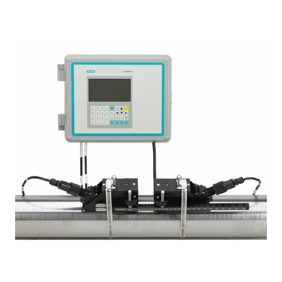
S I T R A N S S T A N D A R D L I Q U I D U L T R A S O I N C F L O W ME T E R
MO D E L S : F U S 1 0 1 0
P R O D U C T I N S T R U C T I O N MA N U A L V 1 . 0
MA Y 2 0 1 6
2 0 1 S O U T H H O U S T O N A V E .
T U L S A , O K 7 4 1 2 7
P H O N E ( 9 1 8 ) 5 8 4 - 4 7 0 0
WWW. E R N I E G R A V E S . C O M
Advertisement
Table of Contents

Related Manuals for Siemens FUS1010


Summary of Contents for Siemens FUS1010
- Page 1 P R O D U C T I N S T R U C T I O N MA N U A L V 1 . 0 MA Y 2 0 1 6 S I T R A N S S T A N D A R D L I Q U I D U L T R A S O I N C F L O W ME T E R MO D E L S : F U S 1 0 1 0 2 0 1 S O U T H H O U S T O N A V E .
- Page 2 ___________________ FUS1010 IP65 NEMA 4X Introduction ___________________ Safety notes ___________________ Description SITRANS F ___________________ Installing/mounting Ultrasonic Flowmeters ___________________ FUS1010 IP65 NEMA 4X Connecting & IP66 NEMA 7 ___________________ Commissioning Operating Instructions ___________________ Functions ___________________ Alarm, error, and system messages ___________________...
- Page 3 Note the following: WARNING Siemens products may only be used for the applications described in the catalog and in the relevant technical documentation. If products and components from other manufacturers are used, these must be recommended or approved by Siemens. Proper transport, storage, installation, assembly, commissioning, operation and maintenance are required to ensure that the products operate safely and without any problems.
-
Page 4: Table Of Contents
Safety notes for connecting ......................37 Transmitter Wiring........................39 5.2.1 Connecting Power........................39 5.2.2 Wiring Temperature Sensor to Transmitter .................43 Navigating the Menu ........................46 Programming the Transmitter ......................49 Sensor Installation ........................53 FUS1010 IP65 NEMA 4X & IP66 NEMA 7 Operating Instructions, 01/2013, A5E02951520-AC... - Page 5 Alarm, error, and system messages ...................... 153 Alarm Codes ..........................153 Service and maintenance ........................155 Maintenance..........................155 Technical support........................155 Return procedures ........................156 Battery disposal......................... 157 Disposal............................. 158 FUS1010 IP65 NEMA 4X & IP66 NEMA 7 Operating Instructions, 01/2013, A5E02951520-AC...
- Page 6 Memory Control Menu .......................132 Table 7- 10 Analog Out Trim Menu Structure ....................133 Table 7- 11 RTD Calibrate Menu Structure....................137 Table 7- 12 Inline Metal and Plastic Pipe Cable Connections ..............142 FUS1010 IP65 NEMA 4X & IP66 NEMA 7 Operating Instructions, 01/2013, A5E02951520-AC...
- Page 7 Input/Output Wiring TB1 7ME39400SA00 - Analog Input Module..........200 Table A- 22 Input/Output Wiring TB2 7ME39400SA00 - Analog Input Module..........201 Table A- 23 Input/Output Wiring TB3 and TB4 7ME39400SA00 - Analog Input Module ......201 FUS1010 IP65 NEMA 4X & IP66 NEMA 7 Operating Instructions, 01/2013, A5E02951520-AC...
- Page 8 Clamp-on Temperature Sensor ....................79 Figure 5-27 Insert Temperature Sensor ......................80 Figure 5-28 Sensor Cable Connections ......................81 Figure 6-1 Final Setup ...........................84 Figure 6-2 Measuring Flow..........................84 Figure 7-1 Sample File ..........................101 FUS1010 IP65 NEMA 4X & IP66 NEMA 7 Operating Instructions, 01/2013, A5E02951520-AC...
- Page 9 7ME39400AL04 Expanded I/O Module ..................191 Figure A-4 7ME39404SB00 Analog Input Module..................197 Figure A-5 Temperature Sensor Inputs .......................199 Figure A-6 7ME39400SA00 - Analog Input Module..................200 Figure A-7 1015CPC-N Serial Interface Cable ....................203 FUS1010 IP65 NEMA 4X & IP66 NEMA 7 Operating Instructions, 01/2013, A5E02951520-AC...
-
Page 10: Introduction
2. Make sure the scope of delivery, and the information on the type plate corresponds to the ordering information. FUS1010 IP65 NEMA 4X & IP66 NEMA 7 Operating Instructions, 01/2013, A5E02951520-AC... -
Page 11: History
Edition Remarks 07/2010 First edition of Operating Instructions for SITRANS FUS1010 IP65 NEMA 4X & IP66 NEMA 7 flow meter. 02/2011 Second edition of Operating Instructions for SITRANS FUS1010 IP65 NEMA 4X & IP66 NEMA 7 flow meter. This document replaces all previous instructions for use. -
Page 12: Safety Notes
Alterations to the product, including opening or improper modifications of the product, are not permitted. If this requirement is not observed, the CE mark and the manufacturer's warranty will expire. FUS1010 IP65 NEMA 4X & IP66 NEMA 7 Operating Instructions, 01/2013, A5E02951520-AC... -
Page 13: Warning Symbols
Protect the device from impact otherwise loss of degree of protection Protective insulation; device in protection class II Laws and directives General requirements Installation of the equipment must comply with national regulations. For example, the National Electrical Codes. FUS1010 IP65 NEMA 4X & IP66 NEMA 7 Operating Instructions, 01/2013, A5E02951520-AC... -
Page 14: Lithium Batteries
Operating Instructions must be observed. NOTICE Material compatibility Siemens can provide assistance with the selection of sensor parts. However, the full responsibility for the selection rests with the customer and Siemens can take no responsibility for any failure due to material incompatibility. -
Page 15: Installation In Hazardous Area
Intrinsically safe data WARNING Explosion Hazard User must install unit with Siemens drawings. With intrinsically safe circuits, use only certified meters appropriate for the transmitter. If a non-conforming supply unit is used, the "fail-safe" type of protection will no longer be effective and the approval certification will be invalid. - Page 16 If a non-conforming infeed is used, the "fail-safe" type of protection will no longer be effective. FUS1010 IP65 NEMA 4X & IP66 NEMA 7 Operating Instructions, 01/2013, A5E02951520-AC...
-
Page 17: Safety Notes
Hazardous (Classified) Location. Install as directed. Disconnect power source before servicing. Keep cover closed when equipment is operating. FUS1010 IP65 NEMA 4X & IP66 NEMA 7 Operating Instructions, 01/2013, A5E02951520-AC... - Page 18 The sales contract contains the entire obligation of Siemens. The warranty contained in the contact between the parties is the sole warranty of Siemens. Any statements contained herein do not create new warranties or modify the existing warranty.
- Page 19 Ex ia for use in potentially expl osive atmosphere containing gases Safety Infor mation for Hazardous Areas Note Ratings under this heading apply to specific model families. Check Your Model Number: FUS1010, 7ME3530, 7ME3533 FUS1010 IP65 NEMA 4X & IP66 NEMA 7 Operating Instructions, 01/2013, A5E02951520-AC...
- Page 20 Zone 1 potentially explosive atmosphere with intrinsically safe circuits of category Ex ia, which can be connected to Category 1 Sensors for use in potentially explosive atmosphere containing gases FUS1010 IP65 NEMA 4X & IP66 NEMA 7 Operating Instructions, 01/2013, A5E02951520-AC...
-
Page 21: Certificates
Certificates are posted on the Internet and on the documentation CD-ROM shipped wit h the device. See also Technical data (Page 179 Certificates on the Internet (http://ww w.siemens.com/processinstrumentation/certificates FUS1010 IP65 NEMA 4X & IP66 NEMA 7 Operating Instructions, 01/2013, A5E02951520-AC... -
Page 22: Description
NEMA 4X and NEMA 7 Transmitters SITRANS FUS1010 Transmitters The SITRANS FUS1010 NEMA 4 and NEMA 7 series transmitters are available in Dual Path and Multi-Path versions. The transmitters include a graphic display providing flow rate, diagnostics data and keypad interface to access on-screen software setup menus. Safety agency approved SITRANS FUS1010 series transmitters have hazardous area certification as indicated in the label examples below. -
Page 23: Figure 3-1 Typical Transmitter Label
● 2 Channel / 2 Path - 7ME3530-2 ● 4-Channel / 4-Path - 7ME3530-9 (Wall Mount only) Figure 3-2 NEMA 4X Transmitter Case Note The NEMA 4X Multi-Path transmitter case is slightly larger. FUS1010 IP65 NEMA 4X & IP66 NEMA 7 Operating Instructions, 01/2013, A5E02951520-AC... -
Page 24: Applications
Access to the Graphic display and keypad setup must be done with cover opened exposing high voltage connections which may cause death or serious injury. Consult local codes for permit needed to setup FUS1010 NEMA 7 units using the graphic display and local keypad to avoid injury. -
Page 25: Theory Of Operation
With accurate signal arrival time available, the flow meter can compute the raw flow velocity from the measured upstream and downstream transit times. FUS1010 IP65 NEMA 4X & IP66 NEMA 7 Operating Instructions, 01/2013, A5E02951520-AC... - Page 26 The shape of this flow profile (for fully developed flow) is defined by the Reynolds number. FUS1010 IP65 NEMA 4X & IP66 NEMA 7 Operating Instructions, 01/2013, A5E02951520-AC...
- Page 27 RAW flow rate (FLOW ) and liquid sonic velocity (VoS) are computed. Using the liquid temperature input (Standard on FUS1010) and the optional user provided pressure input, the measured VoS is then compensated to the value expected for base temperature and pressure conditions (i.e.
- Page 28 The following paragraphs introduce the available flow meter types that include: ● 2-Channel ● 4-Channel ● 2-Path ● 4-Path ● Channe l 1+2 ● Channel 1-2 ● Reflexor (Pag e 140) FUS1010 IP65 NEMA 4X & IP66 NEMA 7 Operating Instructions, 01/2013, A5E02951520-AC...
- Page 29 Pipe A Output Flow Pipe A 4-Channel 4 Channel provides four independent measurement channels that operate simultaneously. Depending on the specific model, 4 Channel supports: Clamp-on Transit-time, In-line Transit-time and Reflexor. FUS1010 IP65 NEMA 4X & IP66 NEMA 7 Operating Instructions, 01/2013, A5E02951520-AC...
- Page 30 Benefits include highest available precision and enhanced immunity to distorted flow profile conditions. ① ③ Sensor Path 1 Average= (Path 1 + Path 2) / 2 ② ④ Sensor Path 2 Pipe (front view) FUS1010 IP65 NEMA 4X & IP66 NEMA 7 Operating Instructions, 01/2013, A5E02951520-AC...
- Page 31 Output sum or difference of CH 1 & CH 2 ② ⑥ Downstream Sensors Channel 2 ③ ⑦ Channel 1 Pipe B (front view) ④ ⑧ CH 1 [+/-] CH 2 Pipe A (front view) FUS1010 IP65 NEMA 4X & IP66 NEMA 7 Operating Instructions, 01/2013, A5E02951520-AC...
- Page 32 The flow meter derives the angle by knowing the fixed position of the sensors, the dimensions of the pipe and the measured transit-time. FUS1010 IP65 NEMA 4X & IP66 NEMA 7 Operating Instructions, 01/2013, A5E02951520-AC...
- Page 33 Reflect mounting automatically corrects for non-axial flow or cross flow since the 2 vectors in a reflected beam are affected in opposite directions, such that the individual cross flow errors cancel each other. FUS1010 IP65 NEMA 4X & IP66 NEMA 7 Operating Instructions, 01/2013, A5E02951520-AC...
-
Page 34: Installing/Mounting
/ air bubbles will be trapped. For liquids it is advantageous to install the sensor in low pipeline sections, at the bottom of a U-section in the pipeline. FUS1010 IP65 NEMA 4X & IP66 NEMA 7 Operating Instructions, 01/2013, A5E02951520-AC... -
Page 35: Use According To Specifications
● Use the sensors as a footboard for installation purposes. ● Change the flow meter in any way. For e.g. decomposition of material in connection with processing, welding and use of accessories and spare parts not approved by Siemens. Note If the flowmeter is not used according to the specifications, the manufacturer cannot be held responsible for any resulting damage. -
Page 36: Mounting The Transmitter
For installation on 2-inch (6 cm) mounting pipe use Pipe Mount Kit CQO:1012NMB-1 (optional - see catalog). See figure below. Note Pipe mounting kit CQO:1012NMB-1 is not available for IP66 NEMA 7 enclosures. FUS1010 IP65 NEMA 4X & IP66 NEMA 7 Operating Instructions, 01/2013, A5E02951520-AC... -
Page 37: Figure 4-1 Pipe Mounting And Mounting Locations For Transmitter
Incorrect installation of weather seals may result in failure to meet to IP65 standards and damage to the equipment. Install weather tight seals at all unused holes using proper cable conduit and close additional holes to IP65 standards. FUS1010 IP65 NEMA 4X & IP66 NEMA 7 Operating Instructions, 01/2013, A5E02951520-AC... -
Page 38: Connecting
Before opening the terminal box check that: ● No explosion hazard exists ● Local safety codes and policy requirements have been followed ● All connection leads are potential free FUS1010 IP65 NEMA 4X & IP66 NEMA 7 Operating Instructions, 01/2013, A5E02951520-AC... - Page 39 If a non-conforming infeed is used, the "fail-safe" type of protection will no longer be effective. FUS1010 IP65 NEMA 4X & IP66 NEMA 7 Operating Instructions, 01/2013, A5E02951520-AC...
-
Page 40: Transmitter Wiring
2. Unscrew the two power supply access cover fasteners and remove access cover. 3. Locate power supply connector J10. Using a flat blade screwdriver, remove plug from connector J10. Set aside. FUS1010 IP65 NEMA 4X & IP66 NEMA 7 Operating Instructions, 01/2013, A5E02951520-AC... -
Page 41: Figure 5-1 Input Power Plug (J10) Wiring
Power Supply connector wires should be stripped AWG 12 - 18 stranded wire or solid conductors. 7. Plug input power plug into connector J10 and secure using two captive connector mounting screws. FUS1010 IP65 NEMA 4X & IP66 NEMA 7 Operating Instructions, 01/2013, A5E02951520-AC... - Page 42 The transmitter must be grounded and the top cover closed before applying power to the device. 10. Connect the power cables to the appropriate power source (90-240 VAC @ 50/60 Hz or 9-36 VDC). Close top cover. 11. Apply power. FUS1010 IP65 NEMA 4X & IP66 NEMA 7 Operating Instructions, 01/2013, A5E02951520-AC...
- Page 43 Connecting 5.2 Transmitter Wiring 12. Within 10 seconds of power-up the transmitter main display will become active and a typical Siemens graphic will appear. The screen also identifies the software version of the unit as shown below. ① Software Version (xx.xx.xx) 13.
-
Page 44: Wiring Temperature Sensor To Transmitter
Remove board and set it aside. Figure 5-2 Analog Input Module Access ① ④ Access Cover Screw Latch ② ⑤ Flow Meter Access to Analog Input Module ③ Power Switch FUS1010 IP65 NEMA 4X & IP66 NEMA 7 Operating Instructions, 01/2013, A5E02951520-AC... -
Page 45: Figure 5-3 Single Channel Temperature Sensor Inputs
Ground Terminals 2 and 3 to Terminal 5 ③ ⑧ Brown To Sensor ④ ⑨ 7ME39600CR (992EC) Series Cable ⑤ Blue Note Alternate color codes for certain 1012EC cables: White = Orange Green = Brown FUS1010 IP65 NEMA 4X & IP66 NEMA 7 Operating Instructions, 01/2013, A5E02951520-AC... - Page 46 AUX. 1 COM AUX. 3 Iin1 input Max w/o Common referenced factory AUX. 2 IN AUX. 4 IN Iin2 Input to meter approval AUX. 2 COM AUX. 4 Iin2 ground. Common FUS1010 IP65 NEMA 4X & IP66 NEMA 7 Operating Instructions, 01/2013, A5E02951520-AC...
-
Page 47: Navigating The Menu
Level C - lists the Level B data Level A Level B Level C Recall Site Setup Pump 1 Pump 2 Channel Enable Create/Name Site Site Security Delete Site Setup Save/Rename Site FUS1010 IP65 NEMA 4X & IP66 NEMA 7 Operating Instructions, 01/2013, A5E02951520-AC... -
Page 48: Table 5- 1 Keypad Function Chart
CTRL and ALT Used as shift keys for alternative key functions. DATALOG Triggers immediate Datalogger report. Plus and Minus [+ / -] Changes the sign of numeric data. FUS1010 IP65 NEMA 4X & IP66 NEMA 7 Operating Instructions, 01/2013, A5E02951520-AC... -
Page 49: Figure 5-5 Typical Installation Menu Screen
Site Name Identified ③ ⑦ Menu Prompt Line (Reverse Video) Highlighted Data ④ ⑧ Current Selected Meter Type Menu Cell Data (right-hand column) Figure 5-5 Typical Installation Menu Screen FUS1010 IP65 NEMA 4X & IP66 NEMA 7 Operating Instructions, 01/2013, A5E02951520-AC... -
Page 50: Programming The Transmitter
Select for summing or subtracting flow from two different pipes. ② Select for measuring two different pipes. (Not available for all models.) ③ Select if two sensors are mounted on the same pipe. FUS1010 IP65 NEMA 4X & IP66 NEMA 7 Operating Instructions, 01/2013, A5E02951520-AC... - Page 51 After site configuration procedures that follow are complete the newly created site must be saved again to retain the new site data. Refer to the Save/Rename Site procedure below. FUS1010 IP65 NEMA 4X & IP66 NEMA 7 Operating Instructions, 01/2013, A5E02951520-AC...
- Page 52 2. Press the <Right Arrow> to select [Liquid Class]. 3. Press the <Right Arrow> again and scroll to desired liquid. 4. Press <ENTER> to save selection. ① Select from list. FUS1010 IP65 NEMA 4X & IP66 NEMA 7 Operating Instructions, 01/2013, A5E02951520-AC...
-
Page 53: Table 5- 2 Pipe Configuration Option List Definitions
Pipe reduction upstream of sensor installation. Norm Entry Not available at this time. Header Inlet Header or pipe manifold upstream of sensor installation. Intrusions Not available at this time. FUS1010 IP65 NEMA 4X & IP66 NEMA 7 Operating Instructions, 01/2013, A5E02951520-AC... -
Page 54: Sensor Installation
Note When installing sensors, do not key in the V/M (Version/Modification) label number as the Sensor Size. FUS1010 IP65 NEMA 4X & IP66 NEMA 7 Operating Instructions, 01/2013, A5E02951520-AC... -
Page 55: Figure 5-6 Reflect Mount (Pipe Shown From Above In 12 O'clock Position)
Compared to Direct mounting, Reflect mount requires almost double the amount of mounting length. Therefore, Direct mount may be the only option if the availability of mounting space is limited. FUS1010 IP65 NEMA 4X & IP66 NEMA 7 Operating Instructions, 01/2013, A5E02951520-AC... -
Page 56: Figure 5-7 Direct Mount (Pipe Shown From Above In 12 O'clock Position)
50.8mm (2-inch) to 330.2mm (13-inch) #88 (2) #152 (2) 7ME396000SM20 330.2mm (13-inch) to 609.6mm (24- #188 (2) #280 (2) inch) 7ME396000SM30 609.6mm (24-inch) to 1219.2mm (48- #152 (4) #312 (4) inch) FUS1010 IP65 NEMA 4X & IP66 NEMA 7 Operating Instructions, 01/2013, A5E02951520-AC... -
Page 57: Figure 5-8 Sensor Alignment (Horizontal Plane)
2. Decide on your mounting mode (Direct or Reflect). Always use Reflect Mode whenever possible. You may only need to use Direct Mode if your pipe is plastic. FUS1010 IP65 NEMA 4X & IP66 NEMA 7 Operating Instructions, 01/2013, A5E02951520-AC... -
Page 58: Sensor Identification And Selection
The sensor part number located on the front face provides a detailed identification. For example, the Part Number: 1011HNS-D1T1-S2 means: ① ⑤ Model Size ② ⑥ Hi Precision Temperature ③ ⑦ NEMA w/F-Conn Agency Approved ④ Pipe Material FUS1010 IP65 NEMA 4X & IP66 NEMA 7 Operating Instructions, 01/2013, A5E02951520-AC... -
Page 59: Figure 5-10 Universal Sensor Label
Sensor Model names for Version 3 op systems are as follows: 1011H Hi Precision, 1011 Universal and 991 Universal Typical Sensor Labels ① Universal Sensor model number ② Sensor size Figure 5-10 Universal Sensor Label FUS1010 IP65 NEMA 4X & IP66 NEMA 7 Operating Instructions, 01/2013, A5E02951520-AC... -
Page 60: Figure 5-11 Hi Precision Sensor Label
3. Press the <Down Arrow> to select [install Sensor]. 4. Press the <Right Arrow> to [Sensor Model]. Press <Right Arrow> and scroll to select the sensor model number on the sensor label. FUS1010 IP65 NEMA 4X & IP66 NEMA 7 Operating Instructions, 01/2013, A5E02951520-AC... - Page 61 10. Sensors can now be mounted. Refer to Sensor Installation mounting procedures and select the mounting mode desired. 11. After sensors are mounted scroll to [Install Complete] and select [Install]. FUS1010 IP65 NEMA 4X & IP66 NEMA 7 Operating Instructions, 01/2013, A5E02951520-AC...
-
Page 62: Reflect Mount
Note that Ltn may be a negative number for direct mount on very small pipes where the sensor spacing overlaps. FUS1010 IP65 NEMA 4X & IP66 NEMA 7 Operating Instructions, 01/2013, A5E02951520-AC... - Page 63 (Refer to the sensor orientation diagram) 9. Tighten the mounting straps to seat the assembly firmly on the pipe. Do not over tighten. FUS1010 IP65 NEMA 4X & IP66 NEMA 7 Operating Instructions, 01/2013, A5E02951520-AC...
-
Page 64: Figure 5-13 Sensor
7ME39600M Mounting Frame Orientation for Single Beam Sensor at 9 o'clock position ⑪ Orientation for Dual Beam Sensor at 10 & 2 o'clock positions Figure 5-14 Sensor Installation FUS1010 IP65 NEMA 4X & IP66 NEMA 7 Operating Instructions, 01/2013, A5E02951520-AC... -
Page 65: Direct Mount
3. Make a note of the Number Index displayed in the [Install] menu. Check to ensure that you have a matched set of sensors. They both should have the same S/N number but marked with either an "A" or "B" (e.g., 100A and 100B). FUS1010 IP65 NEMA 4X & IP66 NEMA 7 Operating Instructions, 01/2013, A5E02951520-AC... -
Page 66: Figure 5-16 Wrap Strap Under Pipe And Attach To Adjusting Screw
8. Attach the second frame to the spacer bar with an index spacer screw into the index hole specified in Step 1. The angle on the frame should be facing away from the direction that the length of the bar is going. FUS1010 IP65 NEMA 4X & IP66 NEMA 7 Operating Instructions, 01/2013, A5E02951520-AC... - Page 67 (see B below). ① ⑤ Sensor 1 Sensor Edge Line ② ⑥ Pipe Spacer Bar ③ ⑦ ④ ⑧ Sensor 2 Line ⑨ Mylar Spacing Guide FUS1010 IP65 NEMA 4X & IP66 NEMA 7 Operating Instructions, 01/2013, A5E02951520-AC...
-
Page 68: Figure 5-17 Wrapping The Mylar Spacing Guide Around The Pipe (End View)
Take the second frame and place it against the edge of the guide with its tapered roller centered on the center mark on the guide. FUS1010 IP65 NEMA 4X & IP66 NEMA 7 Operating Instructions, 01/2013, A5E02951520-AC... -
Page 69: Figure 5-19 Aligning The Sensors For Direct Mode Operation (End View)
(downstream) cables to the sensors and make snug. Attach the other ends to the UP and DN terminals of the transmitter. 25. Replace the Cable Strain Relief bracket. Close top cover. 26. Proceed to Commissioning (Page 83). FUS1010 IP65 NEMA 4X & IP66 NEMA 7 Operating Instructions, 01/2013, A5E02951520-AC... -
Page 70: 1012T Mounting Tracks
[Install Sensor] menu screen. Note the automatic assignment of mounting track part number, plus the designation of the number index. ① Sensor type, size and mounting mode selection. ② Automatic selection of mounting track part number and number index. FUS1010 IP65 NEMA 4X & IP66 NEMA 7 Operating Instructions, 01/2013, A5E02951520-AC... -
Page 71: Figure 5-20 Reflect Mount With Model 1012Tn Mounting Track (Side View)
Tighten the tension screw enough to hold the assembly on the pipe, but still allow rotation. Repeat for the other mounting strap. FUS1010 IP65 NEMA 4X & IP66 NEMA 7 Operating Instructions, 01/2013, A5E02951520-AC... - Page 72 14. Observing the upstream and downstream orientation, attach the UP (upstream) and DN (downstream) cables to the sensors and make snug. Attach the other ends to the UP and DN terminals of the flow meter. FUS1010 IP65 NEMA 4X & IP66 NEMA 7 Operating Instructions, 01/2013, A5E02951520-AC...
- Page 73 ● Reflect Mode Track Assembly - This track rail includes the Tension Screw and REF hole to position one sensor. ● Direct Mode Track Assembly - This track rail has number index holes for inserting an index pin to position the other sensor. FUS1010 IP65 NEMA 4X & IP66 NEMA 7 Operating Instructions, 01/2013, A5E02951520-AC...
-
Page 74: Figure 5-21 Direct Mount 180° Opposed With Mounting Tracks
REF Hole Index Pin ⑤ ⑪ 7ME3950 Series Sensor Upstream Ultrasonic Couplant ⑥ ⑫ 7ME39600M Series Mounting Track Pipe (1012TN, 1012TNH) Figure 5-21 Direct Mount 180° opposed with Mounting Tracks FUS1010 IP65 NEMA 4X & IP66 NEMA 7 Operating Instructions, 01/2013, A5E02951520-AC... - Page 75 For a vertical pipe installation, use a tie, tape or bungee cord to hold the two tracks in place while mounting. 6. Finger-tighten the chain Tension Screw to secure the strap and tracks to the pipe. FUS1010 IP65 NEMA 4X & IP66 NEMA 7 Operating Instructions, 01/2013, A5E02951520-AC...
-
Page 76: Figure 5-22 Wrapping The Mylar Spacing Guide Around The Pipe (End View)
① ③ Overlap Edge Mark on Spacing Guide ② ④ Mark (or fold) exactly at half-way point Circumference Figure 5-23 Finding the Halfway Distance FUS1010 IP65 NEMA 4X & IP66 NEMA 7 Operating Instructions, 01/2013, A5E02951520-AC... -
Page 77: Figure 5-24 Track Rail Alignment
Spacer Guide and the center of the other track aligns at the point where the Spacer Guide ends meet. The tracks should now be 180° apart. Tighten both chains but not too tight. FUS1010 IP65 NEMA 4X & IP66 NEMA 7 Operating Instructions, 01/2013, A5E02951520-AC... -
Page 78: Figure 5-25 Ref And Number Index Pin Locations
Mylar guide as a stop for both tracks and keep them parallel. Align each track with the "center line" you previously marked on the Spacing Guide. Tighten tracks securely. FUS1010 IP65 NEMA 4X & IP66 NEMA 7 Operating Instructions, 01/2013, A5E02951520-AC... -
Page 79: Mounting Temperature Sensors
Insertion style RTD pair (size 2) for FUE1010, 216mm (8.5 7ME39501TJ11 Insertion style RTD pair (size 3) for FUE1010, 292mm (11.5 7ME39501TJ12 Insertion style RTD pair (size 4) for FUE1010, 368mm (14.5 7ME39501TJ13 FUS1010 IP65 NEMA 4X & IP66 NEMA 7 Operating Instructions, 01/2013, A5E02951520-AC... -
Page 80: Figure 5-26 Clamp-On Temperature Sensor
5.6 Mounting Temperature Sensors ① ③ 7ME39600CR 992EC Series Cable Thermal Couplant ② ④ Clamp-on Temperature Sensor (Matched Pipe pair required for FUE1010) ⑤ Mounting Assembly Figure 5-26 Clamp-on Temperature Sensor FUS1010 IP65 NEMA 4X & IP66 NEMA 7 Operating Instructions, 01/2013, A5E02951520-AC... -
Page 81: Sensor Wiring
(downstream) cables to the sensors and make snug. Attach the other ends to the UP and DN terminals of the flow meter (see figure below). 3. Replace the Cable Strain Relief bracket. Close top cover. FUS1010 IP65 NEMA 4X & IP66 NEMA 7 Operating Instructions, 01/2013, A5E02951520-AC... -
Page 82: Figure 5-28 Sensor Cable Connections
Sensor Cables Connected to Transmitter To CH-1 DN ③ ⑦ Cable Strain Relief Bracket To CH-1 UP ④ ⑧ To CH-2 DN Channel 2 ⑨ Channel 1 Figure 5-28 Sensor Cable Connections FUS1010 IP65 NEMA 4X & IP66 NEMA 7 Operating Instructions, 01/2013, A5E02951520-AC... - Page 83 Connecting 5.7 Sensor Wiring FUS1010 IP65 NEMA 4X & IP66 NEMA 7 Operating Instructions, 01/2013, A5E02951520-AC...
-
Page 84: Commissioning
● Device installed in hazardous location meets the requirements described in "Installation in hazardous location (Page 14)" Commissioning Note Refer to [Programming the Transmitter] (Page 49) if needed. 1. Scroll down to [Install Sensor] and press <Right Arrow>. FUS1010 IP65 NEMA 4X & IP66 NEMA 7 Operating Instructions, 01/2013, A5E02951520-AC... -
Page 85: Figure 6-1 Final Setup
3. Observe the Measured Vs window and verify a correct sound velocity measurement (if known). 4. Press the <Down Arrow> to accept sound velocity value. 5. Press the <MENU> key. FUS1010 IP65 NEMA 4X & IP66 NEMA 7 Operating Instructions, 01/2013, A5E02951520-AC... -
Page 86: Empty Pipe Set
To use the Actual MTY command: 1. From [Channel Setup] scroll down to [Install Sensor]. 2. Press the <Right Arrow> to access the [Empty Pipe Set] option list. FUS1010 IP65 NEMA 4X & IP66 NEMA 7 Operating Instructions, 01/2013, A5E02951520-AC... - Page 87 – Empty Pipe Press [ENT] appears on the menu prompt line. 4. Empty the pipe completely, then press <ENTER>. – Fill Pipe Press [ENT] appears on the menu prompt line. 5. Refill the pipe completely, then press <ENTER>. FUS1010 IP65 NEMA 4X & IP66 NEMA 7 Operating Instructions, 01/2013, A5E02951520-AC...
- Page 88 1. From [Channel Setup] scroll down to [Install Sensor]. 2. Press the <Right Arrow> to access the [Empty Pipe Set] option list. 3. Press <Up Arrow> to move the cursor to [Set Empty]. FUS1010 IP65 NEMA 4X & IP66 NEMA 7 Operating Instructions, 01/2013, A5E02951520-AC...
-
Page 89: Installation Menus
4. Press <Right Arrow> to Level D. 5. Scroll using <Down Arrow> to [Sensor Size]. 6. Press <ENTER> select size from list. Note Menu items in bold are required entries to establish operation. FUS1010 IP65 NEMA 4X & IP66 NEMA 7 Operating Instructions, 01/2013, A5E02951520-AC... - Page 90 Time Average / SmartSlew Deadband Control Numeric Entry Memory/Fault Set Fault / Memory Memory Delay (s) Flow Total Units Flow Vol. Units Enter From List Flow Time Units Enter From List FUS1010 IP65 NEMA 4X & IP66 NEMA 7 Operating Instructions, 01/2013, A5E02951520-AC...
- Page 91 Enter From List Delete Pipe Enter From List Sensor Type Enter From List Logger Display Logger Off/Line Wrap / Control No Line Wrap Output Logger Yes/No Circular Memory Yes/No FUS1010 IP65 NEMA 4X & IP66 NEMA 7 Operating Instructions, 01/2013, A5E02951520-AC...
- Page 92 Version View Only Reset Data/Time View Only mm.dd.yy.hh.mm.ss Op System P/N View Only Checksum View only Code View Only System Time View Only mm.dd.yy.hh.mm.ss Language Enter From List FUS1010 IP65 NEMA 4X & IP66 NEMA 7 Operating Instructions, 01/2013, A5E02951520-AC...
- Page 93 Commissioning 6.4 Installation Menus FUS1010 IP65 NEMA 4X & IP66 NEMA 7 Operating Instructions, 01/2013, A5E02951520-AC...
-
Page 94: Functions
The UniMass Table resides within the [Application Data] menu. Refer to Programming the Transmitter (Page 49) for Installation Menu details. [UniMass Table] - From the [Application Data] menu, press the <Right Arrow> to access the UniMass data point editor. FUS1010 IP65 NEMA 4X & IP66 NEMA 7 Operating Instructions, 01/2013, A5E02951520-AC... - Page 95 Use this item to remove all table points. You will need to re-enter all table data if you answer [Yes] to this menu item. [Yes/No] ● Table Active Use this item to tell the flow meter whether to use the UniMass Table. FUS1010 IP65 NEMA 4X & IP66 NEMA 7 Operating Instructions, 01/2013, A5E02951520-AC...
- Page 96 UniMass will not project viscosity and specific gravity measurements beyond the entered limits of the table but rather keep the highest or lowest table entry as its output. FUS1010 IP65 NEMA 4X & IP66 NEMA 7 Operating Instructions, 01/2013, A5E02951520-AC...
- Page 97 2. Press the <Right Arrow> and scroll to select UniMass table type [Constant Temp]. 3. Press the <Right Arrow> and select [Create/Edit Table]. 4. Press <Right Arrow> to highlight [Table Point]. FUS1010 IP65 NEMA 4X & IP66 NEMA 7 Operating Instructions, 01/2013, A5E02951520-AC...
- Page 98 9. Press <Left Arrow>. Scroll to [Table Active] and press <Right Arrow>. 10. Select [Yes] and press <ENTER>. 11. Press <Left Arrow> to return to [Application Data] menu. FUS1010 IP65 NEMA 4X & IP66 NEMA 7 Operating Instructions, 01/2013, A5E02951520-AC...
- Page 99 2. Press the <Right Arrow> and scroll to select UniMass table type [Constant Vs]. 3. Press the <Right Arrow> and select [Create/Edit Table]. 4. Press <Right Arrow> to highlight [Table Point]. FUS1010 IP65 NEMA 4X & IP66 NEMA 7 Operating Instructions, 01/2013, A5E02951520-AC...
- Page 100 <CR> input with a [? for menu] prompt. The flow meter will accept a text file of the correct format into the UniMass table data structure directly. FUS1010 IP65 NEMA 4X & IP66 NEMA 7 Operating Instructions, 01/2013, A5E02951520-AC...
- Page 101 The [Changing Temp & Vs] lookup table must be serially loaded using the HyperTerminal [Send Text File] command. This table can be generated using a utility provided by Siemens, which converts the Vs and temperature data into a uniform 10x10 grid array and formats it appropriately for serial upload.
-
Page 102: Figure 7-1 Sample File
2. Substitute your actual parameters for the parameters in the [UNimass ex table.txt] file shown above. Add or remove as many rows as is necessary to reflect your actual process. FUS1010 IP65 NEMA 4X & IP66 NEMA 7 Operating Instructions, 01/2013, A5E02951520-AC... - Page 103 3. Double-click on [UniMass.exe]. Select [Deg F] or [Deg C]. 4. Click [Browse]. 5. Select [UniMass ex table.txt] text table with your parameter changes in it. Click [Open]. FUS1010 IP65 NEMA 4X & IP66 NEMA 7 Operating Instructions, 01/2013, A5E02951520-AC...
- Page 104 – For a Dual Path system, type: cv 2 – For a Quad Path system, type: cv 3 10. Select the HyperTerminal [Transfer] menu and scroll to the [Send Text File] command. FUS1010 IP65 NEMA 4X & IP66 NEMA 7 Operating Instructions, 01/2013, A5E02951520-AC...
-
Page 105: Selecting Flow Units
1. Press the <MENU> key and [Meter Type] will be highlighted. 2. Press the <Right Arrow> to [2 Channel Flow] and then press <ENTER>. 3. The [2 Channel Flow] menu with appear with [Channel Setup] menu item highlighted. FUS1010 IP65 NEMA 4X & IP66 NEMA 7 Operating Instructions, 01/2013, A5E02951520-AC... -
Page 106: Table 7- 1 Totalizer Modes
Accumulates flow in positive direction only NEGFLOW negative flow Accumulates flow in reverse direction only NETFLOW positive or negative flow Adds to positive total; subtracts from reverse total FUS1010 IP65 NEMA 4X & IP66 NEMA 7 Operating Instructions, 01/2013, A5E02951520-AC... - Page 107 4. Scroll down to the [Totalizer Mode] menu and press the <Right Arrow> to select the Totalizer Mode option list. 5. Press the <Up/Down Arrows> to select the desired mode. 6. Press <ENTER> to store selection. FUS1010 IP65 NEMA 4X & IP66 NEMA 7 Operating Instructions, 01/2013, A5E02951520-AC...
- Page 108 1. Access Si-Ware or, if using a PC, access HyperTerminal from the PC [Programs] menu, then select [HyperTerminal]. 2. In [Connection Description] dialog box, enter a connection name (e.g. FUS1010). Click [OK]. 3. In [Phone Number] dialog box, select [Direct to COM 1 (or COM 2)]. Click [OK] to select.
-
Page 109: Table 7- 2 Totalizer Controls (The "N" In
Clears the Makeup Latch. Refer to the Span Data menu [Set Alarm Levels] and then the [Makeup Latch] On / Off option. (Makeup Latch) *Use the <F1> key as the "Lead-in command" for 4-Path Totalizer operations. FUS1010 IP65 NEMA 4X & IP66 NEMA 7 Operating Instructions, 01/2013, A5E02951520-AC...= Channel Number) -
Page 110: Zero Flow Adjust Menu
(or zero offset) may be present in any installation. To eliminate this residual zero offset Siemens has developed several different methods to insure proper zero flow compensation. The following paragraphs describe each method and when they should be used. - Page 111 You can allow zero averaging for the entire period, or cancel the process at any time by pressing the <ENTER> key. This controls the amount of data the flow meter averages to obtain a zero level. FUS1010 IP65 NEMA 4X & IP66 NEMA 7 Operating Instructions, 01/2013, A5E02951520-AC...
- Page 112 Moreover, pipes of this size frequently have excellent intrinsic zero performance and may not even need zeroing. FUS1010 IP65 NEMA 4X & IP66 NEMA 7 Operating Instructions, 01/2013, A5E02951520-AC...
- Page 113 4. While ZeroMatic initial makeup is running, press <Left Arrow> to abort the process thereby disabling the function. 5. The screen will return to the [Dual Path Flow] menu and highlight the [Operation Adjust] menu cell. FUS1010 IP65 NEMA 4X & IP66 NEMA 7 Operating Instructions, 01/2013, A5E02951520-AC...
-
Page 114: Span Data
Current output of 20mA Current output of 4mA Voltage output of 10 VDC Voltage output of 0 VDC Pulse output of 5000 Hz Pulse output of 0 Hz FUS1010 IP65 NEMA 4X & IP66 NEMA 7 Operating Instructions, 01/2013, A5E02951520-AC... - Page 115 5. Scroll down to [Min Flow].Press <Right Arrow> to input 0% flow rate numeric data for 4mA. Press <ENTER> to store data. ① Input numeric flow data here FUS1010 IP65 NEMA 4X & IP66 NEMA 7 Operating Instructions, 01/2013, A5E02951520-AC...
-
Page 116: Analog Out Setup
Same as Iin1 and Iin2 above but only available for operation in Multi-Path and Arithmetic modes. Note Refer to Appendix A (Page 181) for Analog output connections including connections multi- channel meters. FUS1010 IP65 NEMA 4X & IP66 NEMA 7 Operating Instructions, 01/2013, A5E02951520-AC... - Page 117 2. Press <Right Arrow] to highlight the [Analog Out Setup] menu. 3. Press <Right Arrow> twice to access the [Io1] option list. 4. Move the cursor to the desired data function by pressing <Up/Down Arrow>. FUS1010 IP65 NEMA 4X & IP66 NEMA 7 Operating Instructions, 01/2013, A5E02951520-AC...
- Page 118 1. From the [Analog Out Setup] menu, press <Right Arrow> to access the [Pgen] option list. 2. Move the cursor to the desired data function by pressing <Up/Down Arrow>. 3. To store selection press <ENTER>. FUS1010 IP65 NEMA 4X & IP66 NEMA 7 Operating Instructions, 01/2013, A5E02951520-AC...
-
Page 119: Analog Input Setup
For example, if Iin1 and Iin2 are both assigned to represent pressure (PSIA), the flow meter will only use the pressure input from Iin1. FUS1010 IP65 NEMA 4X & IP66 NEMA 7 Operating Instructions, 01/2013, A5E02951520-AC... - Page 120 2. Move the cursor down to [Aux] by pressing the <Down Arrow> and then press <ENTER>. This enables the port to receive an input current. The cursor moves to [4 mA]. FUS1010 IP65 NEMA 4X & IP66 NEMA 7 Operating Instructions, 01/2013, A5E02951520-AC...
-
Page 121: Expanded I/O Option
All flow meters in the SITRANS F 1010 product family can accept the Expanded I/O Module except 4-Channel flow meters and compact units. Note Use the I/O Data Control menu to assign data functions to the analog outputs. FUS1010 IP65 NEMA 4X & IP66 NEMA 7 Operating Instructions, 01/2013, A5E02951520-AC... - Page 122 ● Analog inputs, when provided, are in the form of 4-20mA non-isolated inputs. ● The meter also has four non-isolated Totalizer command lines providing Totalizer Clear and Totalizer Hold (NoTot) functionality. FUS1010 IP65 NEMA 4X & IP66 NEMA 7 Operating Instructions, 01/2013, A5E02951520-AC...
-
Page 123: Table 7- 6 Typical 2-Channel Flow Meter Expanded I/O Option Connections
Typical 2-Channel Flow Meter Expanded I/O Option Connections Channel Signal AUX Io Meter Menu Display Pgen1 Pgen1 Pgen2 Pgen1 Note The four Aux Io outputs are externally powered. FUS1010 IP65 NEMA 4X & IP66 NEMA 7 Operating Instructions, 01/2013, A5E02951520-AC... - Page 124 Note The method used to create auxiliary current loops makes it impractical to generate the 2mA fault current produced by the primary 4-20mA outputs of the flow meter. FUS1010 IP65 NEMA 4X & IP66 NEMA 7 Operating Instructions, 01/2013, A5E02951520-AC...
-
Page 125: Logger Control
Logger Control Menu Option List Logger Control Display Logger Line Wrap No Line Wrap Output Logger Circular Memory (Available for Multi-Path units only) Est LogTime Left --:-- Clear Logger FUS1010 IP65 NEMA 4X & IP66 NEMA 7 Operating Instructions, 01/2013, A5E02951520-AC... - Page 126 1. Check the flow meter-to-external device connections and your RS-232 Setup parameters (see RS-232 Setup menu). 2. To access the [Output Logger] option list press <Right Arrow>. 3. Scroll the cursor to [Yes] by pressing <Up/Down Arrow>. FUS1010 IP65 NEMA 4X & IP66 NEMA 7 Operating Instructions, 01/2013, A5E02951520-AC...
- Page 127 The [Clear Logger] command erases ALL stored Logger data. Therefore, you should evaluate the currently stored data, and print any valuable information before using this command. Note Saved Sites also consume Logger RAM. FUS1010 IP65 NEMA 4X & IP66 NEMA 7 Operating Instructions, 01/2013, A5E02951520-AC...
-
Page 128: Operation Adjust Menu Settings
Arrow>. 2. At the [Damping Control] menu press the <Right Arrow> and move the cursor down to [Time Average]. 3. To enable Time Average entry press <Right Arrow>. FUS1010 IP65 NEMA 4X & IP66 NEMA 7 Operating Instructions, 01/2013, A5E02951520-AC... - Page 129 3. Press <Right Arrow>to enable numeric entry. 4. Use the numeric keys to type in the desired rate (using selected flow rate units). 5. To register the new value press <ENTER>. FUS1010 IP65 NEMA 4X & IP66 NEMA 7 Operating Instructions, 01/2013, A5E02951520-AC...
- Page 130 Setting Memory Delay 1. To enable numeric entry press <Right Arrow>. 2. Use the number keys to type the delay in seconds. 3. To register the new value press <ENTER>. FUS1010 IP65 NEMA 4X & IP66 NEMA 7 Operating Instructions, 01/2013, A5E02951520-AC...
-
Page 131: Setting Relays
Negative total volume advances 1 digit. Fltwarn System fault warning occurs when 1 or more paths are in fault (multi-path units only). Soft Fault Fault condition - memory mode active. FUS1010 IP65 NEMA 4X & IP66 NEMA 7 Operating Instructions, 01/2013, A5E02951520-AC... - Page 132 3. To access the [Relay Setup] option list press <Right Arrow>. 4. Move the cursor to the desired Relay assignment by pressing the <Up/Down Arrow>. 5. To store selection press <ENTER>. Repeat procedure for all other relays. FUS1010 IP65 NEMA 4X & IP66 NEMA 7 Operating Instructions, 01/2013, A5E02951520-AC...
-
Page 133: Memory Control
You may be able to use an additional block for site or Datalogger storage as a result. Use this command if you seem to be out of memory even though the [Log Memory Left] item indicates free capacity. FUS1010 IP65 NEMA 4X & IP66 NEMA 7 Operating Instructions, 01/2013, A5E02951520-AC... -
Page 134: Analog Output Trim
Analog Out Trim Menu Structure Analog Out Trim Io1 / Io2 Operate Trim@4mA Indicated mA=x.xx Vo1 / Vo2 Operate Trim@2V Indicated V=x.xx Pgen1 / Pgen2 Operate Trim@1kHz Indicated Hz=x.xx FUS1010 IP65 NEMA 4X & IP66 NEMA 7 Operating Instructions, 01/2013, A5E02951520-AC... - Page 135 5. Press <ENTER> to register setting. This adjusts the flow meter’s DAC (digital-to-analog converter) so that a 4mA output corresponds with 4mA on the ammeter. 6. Re-check the ammeter to make sure that it is now reading 4mA. FUS1010 IP65 NEMA 4X & IP66 NEMA 7 Operating Instructions, 01/2013, A5E02951520-AC...
- Page 136 2.00 Volts output corresponds with 2.00 Volts on the multimeter. 6. Re-check the multimeter to make sure that it is now reading 2.00 Volts. FUS1010 IP65 NEMA 4X & IP66 NEMA 7 Operating Instructions, 01/2013, A5E02951520-AC...
- Page 137 1 kHz output corresponds with 1 kHz on the frequency counter. 6. Re-check the frequency counter to make sure that it is now reading 1 kHz. FUS1010 IP65 NEMA 4X & IP66 NEMA 7 Operating Instructions, 01/2013, A5E02951520-AC...
-
Page 138: Resistive Temperature Device (Rtd) Calibration
The [RTD Calibrate] menu appears on all SITRANS 1010 models. Use this menu to calibrate Temperature Sensors to an external standard. It is important to note that Siemens RTD temperature sensors are factory-calibrated for high accuracy. We recommend that before deciding to perform the calibration, check the current RTD reading in the [Diagnostics Data] menu. - Page 139 3. Move the highlight to [Factory] or [User Cal] then press <ENTER>. 4. This triggers the pop-up window: 5. To enable numeric entry <Right Arrow>, then type in the reading of the reference thermometer (e.g., 72.0). FUS1010 IP65 NEMA 4X & IP66 NEMA 7 Operating Instructions, 01/2013, A5E02951520-AC...
- Page 140 Ice Bath RTD Calibration Use deionized water and ice mixture at 0°C (32°F) equilibrium for an ice bath. Ensure temperature with a reference thermometer. Siemens can not assume responsibility for the incorrect design, construction or operation of an Ice Bath.
-
Page 141: Reflexor
● 991 Universal size 2 and 3A High and Very High Temperature versions ● 990 (991 Sensor) The sensor models are also available for submersible and extended temperature applications. FUS1010 IP65 NEMA 4X & IP66 NEMA 7 Operating Instructions, 01/2013, A5E02951520-AC... - Page 142 Use the figure below as a guide to select the proper mounting location. ① ③ Elbow Valve ② ④ Expansion or Contraction Orifice Plate Figure 7-2 Sensor Mounting Examples FUS1010 IP65 NEMA 4X & IP66 NEMA 7 Operating Instructions, 01/2013, A5E02951520-AC...
-
Page 143: Table 7- 12 Inline Metal And Plastic Pipe Cable Connections
In both cases, the cable entry will be on downstream side. Adjacent mounting will provide the maximum sensitivity to flow. Refer to the appropriate sensor installation drawing for the 191N1S (Installation Drawing 191N1S-7). FUS1010 IP65 NEMA 4X & IP66 NEMA 7 Operating Instructions, 01/2013, A5E02951520-AC... - Page 144 Select [Meter Type] as [Reflexor] for the channel that is to be used as Reflexor. Dual channel units may have either one or both channels used in the Reflexor mode. FUS1010 IP65 NEMA 4X & IP66 NEMA 7 Operating Instructions, 01/2013, A5E02951520-AC...
- Page 145 If the Flow Volume and Time units are not set to the default units of Gallons per Minute, then it is recommended to change those units now by use of the [Flow/Total Units] menu. FUS1010 IP65 NEMA 4X & IP66 NEMA 7 Operating Instructions, 01/2013, A5E02951520-AC...
- Page 146 Application dependent parameters are the Low and High Limit Cursors and the Noise Cursor. In most cases, only the Noise Cursor will be required to be adjusted. FUS1010 IP65 NEMA 4X & IP66 NEMA 7 Operating Instructions, 01/2013, A5E02951520-AC...
-
Page 147: Figure 7-5 Spectra Graph Display Screen
② ⑥ Measurement Channel Noise Level Set Cursor ③ ⑦ Site Name Low Limit Cursor ④ ⑧ High Limit Cursor Signal Amplitude Figure 7-5 Spectra Graph Display Screen FUS1010 IP65 NEMA 4X & IP66 NEMA 7 Operating Instructions, 01/2013, A5E02951520-AC... - Page 148 Noise Level Set cursor control. A numeric indication of the Noise Level Cursor position is provided in the highlighted area. Refer to the "Available Adjustments To Spectra Graph" table for details. FUS1010 IP65 NEMA 4X & IP66 NEMA 7 Operating Instructions, 01/2013, A5E02951520-AC...
- Page 149 Set to one half minimum flow if noise is present. In most cases, leave at zero. Carrier Fx Transmit Frequency Code Adjust only under guidance of technical support staff. FUS1010 IP65 NEMA 4X & IP66 NEMA 7 Operating Instructions, 01/2013, A5E02951520-AC...
- Page 150 If greater than 3200 mV, try in-line mounting and/or "detune" Carrier Fx. FFT s/sec Number of FFTs per second FFT Peak Peak FFT Amplitude Carrier Fx Transmit Frequency code FUS1010 IP65 NEMA 4X & IP66 NEMA 7 Operating Instructions, 01/2013, A5E02951520-AC...
- Page 151 For % Deviations above 35, select [Liquid]. For applications that continuously have % Deviations between 25 and 35, proper selection of either [Liquid] or [Slurry] can be confirmed by comparison to a known flow reference. FUS1010 IP65 NEMA 4X & IP66 NEMA 7 Operating Instructions, 01/2013, A5E02951520-AC...
- Page 152 Functions 7.14 Reflexor Other Menu Entries All other flow meter menu entries will operate and be used in the same manner as the transit time flow measurement mode. FUS1010 IP65 NEMA 4X & IP66 NEMA 7 Operating Instructions, 01/2013, A5E02951520-AC...
- Page 153 Functions 7.14 Reflexor FUS1010 IP65 NEMA 4X & IP66 NEMA 7 Operating Instructions, 01/2013, A5E02951520-AC...
-
Page 154: Alarm, Error, And System Messages
The displays shown below indicate where the Alarm Codes appear on the screen. Press <UP> or <DOWN> Arrows to change screen views. 100.0 14.35 354.6597 14.27 31.74 ① Alarm Codes FUS1010 IP65 NEMA 4X & IP66 NEMA 7 Operating Instructions, 01/2013, A5E02951520-AC... - Page 155 Alarm, error, and system messages 8.1 Alarm Codes 68.10 112.38 30.0 -30.0 9/26 12:45 ① Alarm Codes FUS1010 IP65 NEMA 4X & IP66 NEMA 7 Operating Instructions, 01/2013, A5E02951520-AC...
-
Page 156: Service And Maintenance
● Seal integrity of the process connections, cable entries, and cover screws ● Reliability of power supply, lightning protection, and grounds NOTICE Repair and service must be carried out by Siemens authorized personnel only. Note Siemens defines flow sensors as non-repairable products. -
Page 157: Return Procedures
● Information about field service, repairs, spare parts and lots more under "Services." Additional Support Please contact your local Siemens representative and offices if you have additional questions about the device. Find your local contact partner at: http://www.automation.siemens.com/partner See also Local contact person (http://www.automation.siemens.com/partner) -
Page 158: Battery Disposal
In accordance with EU directive 2006/66/EC, batteries are not to be disposed of using municipal waste disposal services. Waste industrial batteries are accepted back by Siemens or by the local Siemens representative. Please talk to your local Siemens contact (http://www.siemens.com/automation/service&support) or follow the return procedures (Page 156) of Siemens. -
Page 159: Disposal
Directive 2002/96/EC on waste electronic and electrical equipment (WEEE). They can be returned to the supplier within the EC or to a locally approved disposal service. Observe the specific regulations valid in your country. FUS1010 IP65 NEMA 4X & IP66 NEMA 7 Operating Instructions, 01/2013, A5E02951520-AC... -
Page 160: Troubleshooting
The following is list of troubleshooting tips and messages that you may encounter. They include explanations and, in some cases, a recommended action. If a problem seems unsolvable, contact your local Siemens office or regional Ultrasonic Flow Representative for expert help at: http://www.automation.siemens.com/partner (http://www.automation.siemens.com/partner). - Page 161 Switching from Reflect to Direct Mount may solve standards. The system will not operate. the problem. However, operation may not be possible if there is poor liquid or pipe wall sonic conductivity. FUS1010 IP65 NEMA 4X & IP66 NEMA 7 Operating Instructions, 01/2013, A5E02951520-AC...
-
Page 162: F4 Reset Procedure
3. To restore operation, press <MENU> to access the installation menu. Create a new site setup or recall a stored site setup. 4. Re-select any Meter Facilities menu items (e.g. RS-232 setup parameters). FUS1010 IP65 NEMA 4X & IP66 NEMA 7 Operating Instructions, 01/2013, A5E02951520-AC... -
Page 163: Test Facilities Graph Screen
The Test Facilities Graph Screen requires significant CPU overhead. The flow meter should not be left in this mode during normal operation where the Datalogger is the primary output or during calibration work. FUS1010 IP65 NEMA 4X & IP66 NEMA 7 Operating Instructions, 01/2013, A5E02951520-AC... - Page 164 Pressing the <Left Arrow> will return you to the graph screen with the selected parameters appearing at the top left corner of the screen. (The sample graph above is shown with all diagnostics items selected). FUS1010 IP65 NEMA 4X & IP66 NEMA 7 Operating Instructions, 01/2013, A5E02951520-AC...
- Page 165 The most important parameter is the digital damping control, which can be accessed by pressing number <1> or <2> on the keypad while in the Signal Graph Screen mode. FUS1010 IP65 NEMA 4X & IP66 NEMA 7 Operating Instructions, 01/2013, A5E02951520-AC...
- Page 166 To access the Digital Damping Control using the Test Facilities Graph Screen, proceed as follows: Note To use the Test Facilities Graph Screen you must have a working site. FUS1010 IP65 NEMA 4X & IP66 NEMA 7 Operating Instructions, 01/2013, A5E02951520-AC...
-
Page 167: Figure 10-2 Setting Digital Damping Factor
● Close proximity to pressure control valves which may generate in-band acoustic noise ● High un-dissolved gas solids content in liquid. ● High electronic noise from variable frequency drives or other external equipment. FUS1010 IP65 NEMA 4X & IP66 NEMA 7 Operating Instructions, 01/2013, A5E02951520-AC... -
Page 168: Figure 10-3 Setting The Mindamp Factor
2. Pressing the <-> key will decrease the MaxDamp Factor by one unit for each key press. To exit this mode, press the <0> key on the keypad. FUS1010 IP65 NEMA 4X & IP66 NEMA 7 Operating Instructions, 01/2013, A5E02951520-AC... - Page 169 <-> keys. The change from the default value (in receive cycles) will appear in the number to the right of the command. 2. To exit this mode, press the <0> key. FUS1010 IP65 NEMA 4X & IP66 NEMA 7 Operating Instructions, 01/2013, A5E02951520-AC...
- Page 170 Tn marker position, adjust the thresholds so that they are well above the baseline "noise" level but below the first major peak. 2. To exit this mode, press the <0> key. FUS1010 IP65 NEMA 4X & IP66 NEMA 7 Operating Instructions, 01/2013, A5E02951520-AC...
-
Page 171: Table 10- 2 Description Of Graph Screen Text Display Parameters
Indicates the signal to noise ratio of the receive signal. Increased damping will increase the S/N ratio as the asynchronous noise reduces. Envelope Percentage change of the signal from Initial Makeup conditions. FUS1010 IP65 NEMA 4X & IP66 NEMA 7 Operating Instructions, 01/2013, A5E02951520-AC... -
Page 172: Table 10- 3 Hot Key Summary
<F1> and <.> Dumps the digitized waveform data over the RS-232 port. You must first leave the Graph Screen mode before invoking this command. FUS1010 IP65 NEMA 4X & IP66 NEMA 7 Operating Instructions, 01/2013, A5E02951520-AC... -
Page 173: Site Setup Data
Maximum signal damping. Use to average digital data when an unstable condition occurs. Min Damping Minimum signal damping. Use to average digital data when an unstable condition occurs. Flow registration correction parameter. FUS1010 IP65 NEMA 4X & IP66 NEMA 7 Operating Instructions, 01/2013, A5E02951520-AC... - Page 174 3. In the [Diagnostic Data] Menu, highlight [Path Select] and select the desired sensor path. Press <ENTER> to select path. 4. Press the <Down Arrow> and scroll to the [Site Setup Data] menu cell. Press the <Right Arrow> to select it. FUS1010 IP65 NEMA 4X & IP66 NEMA 7 Operating Instructions, 01/2013, A5E02951520-AC...
- Page 175 2. Use the numerical keys to input the desired correction value. Press <ENTER> to input value. 3. The new correction value will appear next to the [HF] menu cell as shown below. FUS1010 IP65 NEMA 4X & IP66 NEMA 7 Operating Instructions, 01/2013, A5E02951520-AC...
- Page 176 3. The current measured correction value is displayed (see below). 4. Press <ENTER> again to install this correction value which will now appear next to the [HF] menu cell. FUS1010 IP65 NEMA 4X & IP66 NEMA 7 Operating Instructions, 01/2013, A5E02951520-AC...
- Page 177 The value shown in the [Automatic] pop-up prompt can not be changed and is for user information only. 5. If you decide not to use the [Automatic] selection, press any key other than <ENTER> to abort the operation. FUS1010 IP65 NEMA 4X & IP66 NEMA 7 Operating Instructions, 01/2013, A5E02951520-AC...
-
Page 178: Force Transmit
NOTICE Incorrect Diagnostic Procedures The Force Transmit and Force Frequency diagnostic procedures are preconfigured at the factory and should only be implemented by approved Siemens personnel otherwise damage to the equipment may occur. Restrict use and repair to qualified personnel. - Page 179 3. To complete the Install process after mounting the transducers press <ENTER>. 4. If the Force Transmit diagnostic procedure is not used, the normal [Install Complete] function occurs. FUS1010 IP65 NEMA 4X & IP66 NEMA 7 Operating Instructions, 01/2013, A5E02951520-AC...
-
Page 180: Technical Data
● Temperature Range: -40°C to +120°C (-40°F to +250°F) Dimensions ● 23.6 cm (9.31 in) x 28.7 cm (11.31 in) ● Net weight: 4.1 kg (9.0 lbs.) max FUS1010 IP65 NEMA 4X & IP66 NEMA 7 Operating Instructions, 01/2013, A5E02951520-AC... - Page 181 Please note the following: ● The user is responsible for all changes and repairs made to the device. ● All new components must be provided by Siemens Industry, Inc. ● Restrict repair to faulty components only. ● Do not re-use faulty components.
-
Page 182: Appendix
These connection diagrams apply to the part numbers listed below. Table A- 1 Connection Diagrams and Part Numbers 1010N-2-7 (Sheet 2 of 2) Drawing FUS1010 7ME3530, 7ME3533 FUE1010 7ME3500 FUH1010 7ME3600, 7ME3603 FUS1010 IP65 NEMA 4X & IP66 NEMA 7 Operating Instructions, 01/2013, A5E02951520-AC... -
Page 183: Table A- 2 Input/Output Wiring (Tb2) - 7Me39400Al00 And 7Me39400Al01 I/O Module (For 7Me3500 Or 7Me3530 Only)
Isolated Return Io2+ 4-20mA Output 2 Io2- Isolated Return CGND Chassis GND 0 -5000 Hz Frequency Frequency Output 1 5V TTL output; assignable. Frequency Output 2 5V TTL FUS1010 IP65 NEMA 4X & IP66 NEMA 7 Operating Instructions, 01/2013, A5E02951520-AC... - Page 184 TB2-12 - NEG [-] Total TTL (GND TB2-2 or TB2-4) TB2-13 - POS [+] Total OC (GND TB2-2 or TB2-4) TB2-14 - POS [+] Total TTL (GND TB2-2 or TB2-4) FUS1010 IP65 NEMA 4X & IP66 NEMA 7 Operating Instructions, 01/2013, A5E02951520-AC...
-
Page 185: Table A- 3 Input/Output Wiring (Tb3) - 7Me39400Al00 And 7Me39400Al01 I/O Module
K4 B Relay 4 Normally by CH 1 CH 2 by CH 3 CH 3. Closed (7ME39400AL01 only) K4 C Relay 4 Common FUS1010 IP65 NEMA 4X & IP66 NEMA 7 Operating Instructions, 01/2013, A5E02951520-AC... - Page 186 Terminal Block Wiring - 7ME39400AL03 and 7ME39400AL04 Expanded I/O Module (Refer to manual drawing 1010N-7-7 sheet 2 of 2) These connection diagrams apply to the part numbers listed below. FUS1010 IP65 NEMA 4X & IP66 NEMA 7 Operating Instructions, 01/2013, A5E02951520-AC...
- Page 187 Table A- 4 Connection Diagrams and Part Numbers 1010N-7-7 (Sheet 2 of 2) Drawing FUS1010 7ME3530, 7ME3533 FUE1010 7ME3500 FUH1010 Not Used Figure A-2 7ME39400AL03 and 7ME39400AL04 Expanded I/O Module FUS1010 IP65 NEMA 4X & IP66 NEMA 7 Operating Instructions, 01/2013, A5E02951520-AC...
-
Page 188: Table A- 5 Input/Output Wiring (Tb2) - 7Me39400Al03 And 7Me39400Al04 Expanded I/O Module
TB2-9 - NEG [-] Total OC 0-10V Load 10k ohm (min) TB2-10 - NEG [-] Total TTL ③ ⑥ 4-20mA Load 1k ohm (max) 0-10V Load 10k ohm (min) FUS1010 IP65 NEMA 4X & IP66 NEMA 7 Operating Instructions, 01/2013, A5E02951520-AC... -
Page 189: Table A- 6 Input/Output Wiring (Tb3) - 7Me39400Al03 And 7Me39400Al04 Expanded I/O Module
K4 B Relay 4 Normally Closed (7ME39400AL04 only) K4 C Relay 4 Common K1-A *K1-B K1-C K2-A *K2-B K2-C K3-A *K3-B K3-C K4-A *K4-B K4-C FUS1010 IP65 NEMA 4X & IP66 NEMA 7 Operating Instructions, 01/2013, A5E02951520-AC... -
Page 190: Table A- 7 Input/Output Wiring (Tb4) - 7Me39400Al03 And 7Me39400Al04 Expanded I/O Module
+30V max. Same as TB2-3 conditions. Supply Io4 Power AUX I04- Io4 4-20mA Io4 Signal Output Note Auxiliary 4-20mA loops are assigned and spanned under menu control of Vo and PGEN outputs. FUS1010 IP65 NEMA 4X & IP66 NEMA 7 Operating Instructions, 01/2013, A5E02951520-AC... - Page 191 These connection diagrams apply to the part numbers listed below. Table A- 8 Connection Diagrams and Part Numbers 1010N-7-7 (Sheet 2 of 2) Drawing FUH1010 7ME3600, 7ME3603 FUS1010 Not Used FUE1010 Not Used FUS1010 IP65 NEMA 4X & IP66 NEMA 7 Operating Instructions, 01/2013, A5E02951520-AC...
-
Page 192: Figure A-3 7Me39400Al04 Expanded I/O Module
Appendix A.2 I/O Connections and Wiring Figure A-3 7ME39400AL04 Expanded I/O Module FUS1010 IP65 NEMA 4X & IP66 NEMA 7 Operating Instructions, 01/2013, A5E02951520-AC... -
Page 193: Table A- 9 Input/Output Wiring (Tb2) - 7Me39400Al04 Expanded I/O Module
2mA if assigned to flow rate and under fault Vo2+ 0-10 Volt Output conditions. Vo1- Ref. Ground Vo1+ 0-10 Volt Output DPGEN_2-Ø2 TTL/CMOS DPGEN_1-Ø2 DPGEN_2-Ø1 TTL/CMOS DPGEN_1-Ø1 FUS1010 IP65 NEMA 4X & IP66 NEMA 7 Operating Instructions, 01/2013, A5E02951520-AC... -
Page 194: Table A- 10 Open Collector User Resistor Recommendations
Maximum current into the transistor is 100mA. Maximum Voltage is +36 VDC. NOTICE Transistor Damage Negative voltages with respect to ground will permanently damage transistors. Use caution when applying power to circuit boards. FUS1010 IP65 NEMA 4X & IP66 NEMA 7 Operating Instructions, 01/2013, A5E02951520-AC... -
Page 195: Table A- 11 Input/Output Wiring (Tb3) - 7Me39400Al04 Expanded I/O Module
Alarm or control Alarm or control functions set by functions set by CH 5. K4 B Relay 4 Normally Closed CH 3. (7ME39400AL04 only) K4 C Relay 4 Common FUS1010 IP65 NEMA 4X & IP66 NEMA 7 Operating Instructions, 01/2013, A5E02951520-AC... -
Page 196: Table A- 12 Input/Output Wiring (Tb4) - 7Me39400Al04 Expanded I/O Module
AUX Io4 Vc: 24 VDC typical (+15 VDC to +30 VDC max) Loop Power : 1000 ohms (max), Loop wire resistance plus user's input load resistance I: 4-20mA FUS1010 IP65 NEMA 4X & IP66 NEMA 7 Operating Instructions, 01/2013, A5E02951520-AC... - Page 197 Flow meter requires external power supply. Shunt as shown. Current is controlled within loop. 4-20mA inputs and outputs are isolated. AUX Io1 AUX Io2 AUX Io3 AUX Io4 Vc = +30V (max) Loop Supply 1k ohm (max) FUS1010 IP65 NEMA 4X & IP66 NEMA 7 Operating Instructions, 01/2013, A5E02951520-AC...
- Page 198 TB1 through TB4 and 991T or 1011T series temperature sensors. Note Supply and Return temperature sensor designations when used with FUE1010 series energy flowmeter. Note Alternate color codes for certain 1012EC cables: White = Orange Green = Brown FUS1010 IP65 NEMA 4X & IP66 NEMA 7 Operating Instructions, 01/2013, A5E02951520-AC...
- Page 199 Channel 2 Tr (Return Temperature) 1000 Ft max w/o TB4-2 White RTD Voltage High factory approval TB4-3 Green RTD Voltage Low TB4-4 RTD Current Low TB4-5 Blue Ground FUS1010 IP65 NEMA 4X & IP66 NEMA 7 Operating Instructions, 01/2013, A5E02951520-AC...
- Page 200 Terminal Board 2 ③ ⑧ Brown Terminal Board 5 ④ ⑨ To Sensors ⑤ ⑩ Blue Terminal Board 4 ⑪ Terminal Board 3 Figure A-5 Temperature Sensor Inputs FUS1010 IP65 NEMA 4X & IP66 NEMA 7 Operating Instructions, 01/2013, A5E02951520-AC...
- Page 201 Channel 1 Ts (Supply Temperature) 1000 Ft max w/o TB1-2 White RTD Voltage High factory approval TB1-3 Green RTD Voltage Low TB1-4 RTD Current Low TB1-5 Blue Ground FUS1010 IP65 NEMA 4X & IP66 NEMA 7 Operating Instructions, 01/2013, A5E02951520-AC...
- Page 202 AUX. 4 IN Iin2 Input to meter factory AUX. 2 COM AUX. 4 COM Iin2 Common ground. approval Net load is 335 ohms when safety barriers are used. FUS1010 IP65 NEMA 4X & IP66 NEMA 7 Operating Instructions, 01/2013, A5E02951520-AC...
-
Page 203: Rs-232 Connection
You can use a DOS-based communications program also. Make sure that your PC is loading the ANSI.SYS driver via your Config.sys file. Set the program’s RS-232 parameters to match those of the flow meter (see HyperTerminal example screen on the following pages). FUS1010 IP65 NEMA 4X & IP66 NEMA 7 Operating Instructions, 01/2013, A5E02951520-AC... - Page 204 Notes Weatherproof Portable DB-9F - Amphenol CQO:1015CPC-WP Except Energy Flow meter FUE1010/FUP1010 DB-9F - DB-9F CQO:1015CPC-P Use for Energy WP All NEMA 4X DB-9F - 3 Wire CQO:1015CPC-N FUS1010 IP65 NEMA 4X & IP66 NEMA 7 Operating Instructions, 01/2013, A5E02951520-AC...
- Page 205 ● PC: Refers to an IBM compatible, DB-9 serial Com port. ● FUS1010 NEMA 4: Includes all models (N, DN, MN, FUE, EXCEPT those with "A1" option). Termination is made to the 1010N-2 I/O Data Module. Flow meter end of cable is un-terminated wire.
- Page 206 Connect the cable between the flow meter and your PC using the 25-pin, 9-pin or USB to RS-232 adapter connector, depending upon the port’s architecture. FUS1010 IP65 NEMA 4X & IP66 NEMA 7 Operating Instructions, 01/2013, A5E02951520-AC...
- Page 207 Click [OK] to select the [Com 1 (or 2) Properties] Dialog box. Set up your RS-232 parameters as shown in the example below. Left-click on the [OK] button. FUS1010 IP65 NEMA 4X & IP66 NEMA 7 Operating Instructions, 01/2013, A5E02951520-AC...
- Page 208 [File], sliding the cursor to [Save], then clicking [OK] on the Save dialog box. 10. The next time you want to use HyperTerminal: FUS1010 IP65 NEMA 4X & IP66 NEMA 7 Operating Instructions, 01/2013, A5E02951520-AC...
- Page 209 To maintain a longer connection type: Menu 1000 and press <Enter>. The optional number is the amount in minutes that the connection will be maintained. Typing [Menu 1000] essentially keeps the interface active until you cancel it. FUS1010 IP65 NEMA 4X & IP66 NEMA 7 Operating Instructions, 01/2013, A5E02951520-AC...
- Page 210 Current active site setup name. The [1] The flow Total display. indicates that the measurement channel is active. ② ④ The current measured liquid sonic velocity. The current flow reading and flow units. FUS1010 IP65 NEMA 4X & IP66 NEMA 7 Operating Instructions, 01/2013, A5E02951520-AC...
- Page 211 It is recommended to capture this information into a file with a "csv" extension, which can be easily imported into MS Excel. FUS1010 IP65 NEMA 4X & IP66 NEMA 7 Operating Instructions, 01/2013, A5E02951520-AC...
- Page 212 5. On the PC type the proper command for the data desired (Logger, Site, or DP) and then press [Enter] key. 6. The data should begin streaming on the HyperTerminal screen. FUS1010 IP65 NEMA 4X & IP66 NEMA 7 Operating Instructions, 01/2013, A5E02951520-AC...
- Page 213 3. To restore operation, press <MENU> to access the Installation Menu. Create a new site setup or recall a stored site setup. Re-select any Meter Facilities items (e.g., RS-232 setup parameters). FUS1010 IP65 NEMA 4X & IP66 NEMA 7 Operating Instructions, 01/2013, A5E02951520-AC...
-
Page 214: Flowrate Calibration And Calibration Tables
When selected, the flow meter uses no slope adjustment at all. Output data is still zeroed and corrected for Reynolds number, but no slope adjustment is imposed on the flow meter’s flow register. FUS1010 IP65 NEMA 4X & IP66 NEMA 7 Operating Instructions, 01/2013, A5E02951520-AC... - Page 215 Thus an entry of -3% will multiply the rate register by 0.97, for example. To calculate Kc: FUS1010 IP65 NEMA 4X & IP66 NEMA 7 Operating Instructions, 01/2013, A5E02951520-AC...
- Page 216 3. A calibration factor, a number usually close to 1.00, is entered as a positive and a negative flow rate correction factor (termed PosFlow Corr and NegFlow Corr) for each of the desired index points. FUS1010 IP65 NEMA 4X & IP66 NEMA 7 Operating Instructions, 01/2013, A5E02951520-AC...
-
Page 217: Setup Procedure For Wet-Flow Calibration
Each flow calibration is assigned a unique site name. Usually, the site name corresponds to the pipe size. For example, a 3-inch carbon steel, schedule 40 pipe would be given the name "3CS40." FUS1010 IP65 NEMA 4X & IP66 NEMA 7 Operating Instructions, 01/2013, A5E02951520-AC... - Page 218 4. Select [Full Site Setup] and use the <Right Arrow> to select [Channel Setup]; then select [Recall Site Setup]. 5. Use the <Down Arrow> to scroll to the site name indicated on the Calibration Diagnostic Data Sheet and then press <ENTER>. FUS1010 IP65 NEMA 4X & IP66 NEMA 7 Operating Instructions, 01/2013, A5E02951520-AC...
- Page 219 2. Use the numeric keys to change the Estimated Vs to the Estimated Vs value of the customer selected liquid. 3. To enter new Estimated Vs value press <ENTER>. FUS1010 IP65 NEMA 4X & IP66 NEMA 7 Operating Instructions, 01/2013, A5E02951520-AC...
- Page 220 2. Use the numeric keys to rename the Transfer Installed site with the same site name used above, but with a "T" appended to the end of the site name (e.g., 3CS40T). 3. Press <ENTER> to store data. FUS1010 IP65 NEMA 4X & IP66 NEMA 7 Operating Instructions, 01/2013, A5E02951520-AC...
- Page 221 Appendix A.5 Setup Procedure for Wet-Flow Calibration FUS1010 IP65 NEMA 4X & IP66 NEMA 7 Operating Instructions, 01/2013, A5E02951520-AC...
-
Page 222: Appendix
Appendix Installation/Outline Drawings The following are the installation and outline drawings for the SITRANS FUS1010 NEMA 4X flow meter. 1010NS2-7 Rev D - Installation Drawing, 1010 Series Flow Computer, Agency Approved 1010N-7-7 Rev 08 - Installation Wiring, Expanded I/O Module... - Page 223 990TDMVH-7B Rev F - Installation Drawing, 990 Series Transducer, Direct Mode, Very High Temp. 990TRMVH-7B Rev F - Installation Drawing, 990 Series Transducer, Reflect Mode, Very High Temp. FUS1010 IP65 NEMA 4X & IP66 NEMA 7 Operating Instructions, 01/2013, A5E02951520-AC...
- Page 288 Datalogger contents either on-screen or transmit it to an external device via the RS-232 serial port. The amount of Datalogger memory depends on how many sites reside in Site Storage memory. FUS1010 IP65 NEMA 4X & IP66 NEMA 7 Operating Instructions, 01/2013, A5E02951520-AC...
- Page 289 Local Display Refers to the transmitter integral display screen. Menu Sub-sections of the Installation Menu that allow you to define specific operational functions (e.g., RS-232 Setup). FUS1010 IP65 NEMA 4X & IP66 NEMA 7 Operating Instructions, 01/2013, A5E02951520-AC...
- Page 290 Lists of options presented at menu cells that allow you to select either a single item or multiple items (depending on the function that the menu cell controls). Parameters Refers to value (either numeric or list selection) stored in a menu cell. FUS1010 IP65 NEMA 4X & IP66 NEMA 7 Operating Instructions, 01/2013, A5E02951520-AC...
- Page 291 Site Storage Memory to store configurable operating parameters such as pipe, liquid or gas tables. Si-Ware Siemens software program that interfaces with Siemens flow meters to assess flow meter installation conditions and to collect data for comparison with prior baseline data. Spacing Index Refers to the Number Index used by the flow meter to determine the space between the upstream and downstream sensors on clamp-on systems.
- Page 292 A Totalizer pulse count function used for Batching or Sampling. Transducer Also known as sensor. Vaer The flow meter’s aeration percent output. The sonic propagation velocity of a pipe. The sonic velocity of a liquid or gas. FUS1010 IP65 NEMA 4X & IP66 NEMA 7 Operating Instructions, 01/2013, A5E02951520-AC...
- Page 293 Glossary FUS1010 IP65 NEMA 4X & IP66 NEMA 7 Operating Instructions, 01/2013, A5E02951520-AC...
-
Page 294: Index
Hazardous area Connecting Sensors to the Transmitter, 80 Safety information, 16 Customer Support Hotline, 155 Hazardous area safety requirements, 15 History, 10 Hotline, 155 Damping Control, 127 Datalogger FUS1010 IP65 NEMA 4X & IP66 NEMA 7 Operating Instructions, 01/2013, A5E02951520-AC... - Page 295 Safety instructions, 33 Time Average, 127 Totalizer Mode Controls, 107 Totalizer Modes, 105 Transmitter Labels, 22 Reflexor Typical Flowmeter Applications, 23 Diagnostic Data, 149 Typical Industries Serviced, 24 FUS1010 IP65 NEMA 4X & IP66 NEMA 7 Operating Instructions, 01/2013, A5E02951520-AC...
- Page 296 Expanded I/O Module, 185 I/O Module, 181 Wiring Temperature Sensor to the Analog Input Module, 43 Zero Flow Compensation Methods, 109 Actual Zero, 109 AutoZero, 109 ReversaMatic, 109 ZeroMatic, 110 FUS1010 IP65 NEMA 4X & IP66 NEMA 7 Operating Instructions, 01/2013, A5E02951520-AC...
- Page 297 Index FUS1010 IP65 NEMA 4X & IP66 NEMA 7 Operating Instructions, 01/2013, A5E02951520-AC...
- Page 298 S I E ME N S ® S I T R A N S S T A N D A R D L I Q U I D U L T R A S O I N C F L O W ME T E R MO D E L S : F U S 1 0 1 0 E R N I E G R A V E S S E R V I C E A N D S U P P O R T E E r n i e G r a v e s i s c o mmi t t e d t o a s s u r i n g a l l o f o u r c u s t o me r s r e c e i v e t h e i d e a l f l o w s o l u t i o n f o r t h e i r a p p l i c a t i o n ,...
Need help?
Do you have a question about the FUS1010 and is the answer not in the manual?
Questions and answers