Table of Contents
Advertisement
Advertisement
Table of Contents

Related Manuals for Dentsply Sirona Schick 33

Summary of Contents for Dentsply Sirona Schick 33
- Page 1 Schick USB Module and Sensors User Guide Schick 33 Schick Elite 100003870 Sirona Dental, Inc. 30-30 47 Avenue, Suite 500 Long Island City, NY 11101 (718) 937-5765 (718) 937-5962 (fax) Sirona Dental Systems GmbH Fabrikstr. 31 D-64625, Bensheim Germany PART NUMBER 100003870 REV. 4...
- Page 2 Copyright 2018 by Dentsply Sirona, Inc. All Rights Reserved Sirona. Dental products are covered by one or more US patents. For a current listing, please type Patent Notice into the Search box of the Schick by Sirona website or enter the following page information into your browser’s address bar.
-
Page 3: Table Of Contents
NTERFACE OPERATION ..........................12 4.1..........................12 PERATING THE YSTEM 4.2............................13 SING ENSOR 4.3..............................22 ETECT SCHICK 33 ............................25 5.1. 33 ................................. 25 CHICK 5.2....................26 ESOLUTION MAGE CQUISITION 5.3....................28 HARPEN AND ESOLUTION MAGES 5.4. - Page 4 10.3..........................62 ERIODIC AINTENANCE 10.4............................. 63 UALITY ROCEDURE ACCESSORIES ..........................65 11.1. 33/E USB I .................... 65 CHICK LITE NTERFACE OLDER 11.2..........................66 CHICK ENSOR OLSTER APPENDIX A. REFERENCE ......................68 A-1........................68 EMOVAL AND EPLACEMENT A-2.
- Page 5 List of Figures Figure 1. Schick 33/Elite USB Interface Cable Connections .................... 9 Figure 2. Schick 33/Elite USB Interface LED and Connector Views ................25 Figure 3. Sharpen Slider Menu Selections ........................... 28 Figure 4. Sharpen Slider (Top Position) ..........................30 Figure 5.
- Page 6 USB Interface, and the USB cable for any signs of physical damage or defect. Sensor and USB Interface surfaces should have a smooth finish, with no evidence of chipping or damage. If detected, contact your local distributor of Dentsply Sirona products for further instructions. Operate Sensor and USB Interface as Directed Always use the Sensor and USB Interface in accordance with the directions and recommendations contained in this User Guide.
- Page 7 Any instrumentation or equipment for professional use located near the Sensor and USB Interface must conform to Electromagnetic Compatibility regulations, to which the EMC tables in this document’s Appendix serve as guidance. Non-conforming equipment, with known poor immunity to electromagnetic fields, may not operate properly unless they are installed at a distance of at least 10 feet (3m) and supplied by a dedicated electrical line.
- Page 8 Ensure Proper System and PC Workstation Installation and Operation The Sensor and USB Interface have been determined to be in accordance with international safety standards and are deemed suitable for use within the patient area, which extends from the patient for a distance of 5 ft (1.5m).
- Page 9 An improperly attached cable may cause an intermittent connection and prevent the Sensor from operating effectively. Refer to either the Schick 33 or the Schick Elite sections for complete instructions. Product Manuals from Dentsply Sirona The contents of this manual are subject to change without prior notice.
- Page 10 Explanation of Symbols Dentsply Sirona products display markings to indicate compliance with regulatory requirements and applicable technical standards. Symbols and Descriptions YMBOL ESCRIPTION Indicates Class II equipment in accordance with applicable medical device safety standards (IEC/EN/UL 60601-1) Indicates Type BF equipment in accordance with applicable...
- Page 11 Waste Electrical and Electronic Equipment Background The European Union’s Waste Electrical and Electronic Equipment (WEEE) Directive (2002/96/EC) has been implemented in member states as of August 13, 2005. This directive, which seeks to reduce the waste of electrical and electronic equipment through re-use, recycling, and recovery, imposes several requirements on producers.
- Page 12 Reporting According to the WEEE Directive, Dentsply Sirona or its Dealers will ensure that information needed to calculate the financial obligations with respect to EEE products will be provided as required. WEEE from Users other than Private Households According to the WEEE Directive, Dentsply Sirona or its Dealers will fulfill its obligations for the management of WEEE from users other than private households.
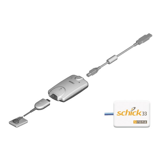
- Page 13 Schick 33 / Schick Elite Systems SCHICK 33 Schick 33 Sensor with Schick 33/Elite USB Interface and USB Cable SCHICK ELITE Schick Elite Sensor with Schick 33/Elite USB Interface and USB Cable Schick USB Module and Sensors 100003870 Rev. 4...
- Page 14 (This page is intentionally blank) 100003870 Rev. 4 Schick USB Module and Sensors...
-
Page 15: System Overview
USB device. “Sensors” refer to Schick 33 and Schick Elite Sensors. “USB Interface” refers to the Schick 33/Elite USB Interface, which provides a physical and electronic connection between the Sensor and the imaging PC. -
Page 16: Replaceable Cable
Details on replacing Sensor cables may be found in the Schick 33 and the Schick Elite sections of this document. 100003870 Rev. 4... -
Page 17: Pc Workstation Description
1.5. PC Workstation Description The PC workstation connects to the USB Interface via USB cable (supplied separately) and serves as the host for CDR DICOM or other compatible imaging software products. The workstation provides the capability to display, manipulate, store, and print images acquired from Schick Sensors. -
Page 18: Software Available For Schick Sensors
Schick Elite Sensors as well, and also with our other Sensor and USB products. Schick Elite and Schick 33 Sensors can be detected automatically by CDR software when connected (depending on your preferences) via Schick 33/Elite USB Interface to a PC workstation. -
Page 19: Installation
Procedures for installing these files are found on the following pages. If you are using a Schick 33/Elite USB Interface for the first time, or if either is being used on a different PC workstation for the first time, you will need to install the device driver. -
Page 20: Uninstalling The Previous Schick 33/Elite Usb Driver
2.3. Uninstalling the Previous Schick 33/Elite USB Driver NOTE: Customers will not need to uninstall the previous Schick 33/Elite driver unless prompted by the software or instructed by customer support. A. Exit CDR DICOM (or other compatible imaging program). B. Verify that the USB Interface is NOT connected to laptop or desktop PC. -
Page 21: Installing The Schick 33/Elite Usb Driver
Installing the Schick 33/Elite USB Driver PLEASE NOTE: Installation on other operating systems is similar to Windows 7, described below. A. Insert the Schick 33/Elite USB Interface Driver disk into your CD or DVD drive. B. Click the Install Schick USB Driver button on the start page. - Page 22 Setup will copy the driver to your workstation. A. Click Finish. B. Remove the USB Interface Driver CD. C. Continue with the next section to connect the USB Interface. 100003870 Rev. 4 Schick USB Module and Sensors...
-
Page 23: Connecting The Schick 33/Elite Usb Interface
An illustration of the Sensor and USB Interface are shown in Figure 1 (below). For a description of cable connections to the device, refer to Table 1 (below). Figure 1. Schick 33/Elite USB Interface Cable Connections Table 1. Schick 33/Elite USB Interface Cable Connections UMBER... -
Page 24: Led Indicators
3. LED Indicators 3.1. Schick 33/Elite USB Interface Table 2. Schick 33/Elite USB Interface LED Indications (Normal Conditions) ENSOR ESCRIPTION DICOM ENSOR ENSOR EADY ONNECTED TATUS CQUIRE Flashing every Ready for image Connected Running ½ - 1½ acquisition seconds Connected... - Page 25 ENSOR ESCRIPTION DICOM ENSOR ENSOR EADY ONNECTED TATUS CQUIRE Over current Running condition. Replace Connected or not Sensor cable. running Replace Sensor if problem persists. Low USB voltage Connected Running condition. Use or not or not ON or OFF ON or OFF Amber Schick USB cable or connected...
-
Page 26: Operation
4. Operation 4.1. Operating the System 4.1.1. Power On 1. Turn on the PC workstation used with imaging applications. 2. Connect the “B” end of the cable to the USB Interface (if not connected already). 3. Connect the “A” end of the cable to the PC work-station (if not connected already). -
Page 27: Using Your Sensor
4.2. Using Your Sensor 4.2.1. Sensor Sheaths Sirona sheaths are required for Sensors. New sheaths are required for each new patient and must be disposed of properly after patient use. Sensor holders (if they are the disposable type) should follow the same procedure. - Page 28 4.2.2. Sensor Positioning To achieve stable Sensor positioning during X-ray exams, use the appropriate tabs and holders available with the Schick Sensors. Using an appropriate Sensor positioning system, adjusting the X-ray setting depending on intraoral position, and placing the X-ray source as close as possible to the imaging area of the Sensor: all of these contribute towards obtaining quality digital X-ray images.
-
Page 29: Table 4. Proper Sensor Removal From Sheath (Aimright Autoclavable System)
Table 4. Proper Sensor Removal from Sheath (AimRight Autoclavable System) XAMPLES CTIONS 1. Begin by pinching the distal end of the Sensor out of the sheath. 2. As the Sensor is pushed into the wider area of the sheath, gently slide the sheath away from the Sensor. -
Page 30: Table 5. Proper Sensor Removal From Sheath (Aimright Adhesive System)
Table 5. Proper Sensor Removal from Sheath (AimRight Adhesive System) XAMPLES CTIONS 1. Keeping the Sensor attached to the positioning tab, grasp the aiming bar where it joins the Sensor and begin pushing the distal end of the Sensor out of the sheath. 2. -
Page 31: Table 6. Sensor Positioning (Aimright Grip System)
Table 6. Sensor Positioning (AimRight Grip System) XAMPLES LACEMENT NSTRUCTIONS Maxillary Anterior Place the distal end of the sensor against the roof of the mouth, with the incisal edge of the teeth against the front of the tab. Sensor should be parallel to the long axis of the maxillary anterior teeth. - Page 32 XAMPLES LACEMENT NSTRUCTIONS Vertical Bitewing The sensor should enter the mouth horizontally. Once past the incisors, “roll” it into a vertical position. Sensor should be placed with the cable pointing upwards toward the hard palate. Ensure the ring is as close to the patient’s face as possible and place the x-ray head against the ring.
-
Page 33: Table 7. Examples Of Sensor-To-Image Orientation
Table 7. Examples of Sensor-to-Image Orientation ENSOR NVERSE IXELS IRCLED ENSOR RIENTATION OCATION MAGE RIENTATION Patient's left side Left Bitewing Patient's upper jaw Anterior Periapical, Maxillary Schick USB Module and Sensors 100003870 Rev. 4... - Page 34 4.2.4. Taking X-rays NOTE: Refer to the CDR DICOM User Guide, Schick P/N 1051047, for detailed information on the use and operation of CDR DICOM software. Start CDR DICOM from the Windows Start button or by clicking the shortcut to CDR DICOM for Windows on your desktop.
- Page 35 IMPORTANT! To avoid exposing the patient to unnecessary X-rays, ensure that the CDR exam window viewbox is flashing green (default color) in AutoTake mode, or that the message, “Waiting to take X-ray,” is displayed before triggering the X-ray source. A. If your acquisition mode is set to AutoTake, the first empty view box in the exam is pre-selected and flashes green (default setting).
-
Page 36: Autodetect
Schick device before using it. Schick devices supported by CDR AutoDetect include: Schick 33/Elite USB interfaces Paired Schick WiFi Interfaces Standard (CDR) and high-speed (CDR Remote HS) remote modules ... - Page 37 4.3.3. How Schick Devices are Detected For CDR AutoDetect to recognize a Schick device, the device must be connected to the specific PC workstation used during imaging. Once the Schick device is connected, we say that it is “known” by CDR AutoDetect, which informs the imaging program to begin using that device.
- Page 38 4.3.4. Changing Schick USB Devices When a known Schick USB device is plugged into the system, a notification window appears momentarily, indicating that the device was just detected and has become active. It is also possible to interact with the CDR AutoDetect feature by clicking on the notification window when it appears or by double- clicking on the CDR AutoDetect graphic in the Windows system tray when CDR AutoDetect is enabled.
-
Page 39: Schick 33
Available in three Sensor sizes (0,1, and 2), three Sensor cable lengths (3-, 6-, and 9-ft), and incorporating Schick’s unique field-replaceable cable design, Schick 33 provides an unprecedented level of resolution and control over intra-oral digital images. With pre-set clinical mapping options and an adjustable image sharpness feature, Schick 33 displays your images just the way you want to see them. -
Page 40: High Resolution Image Acquisition
28 lp/mm. The above image shows a line pair measurement phantom captured with a size 2 Schick 33 Sensor. The phantom measures up to 28 lp/mm, which the Schick Sensor is able to demonstrate in the enlarged section highlighted in red. - Page 41 5.2.2. Selecting Standard Resolution Acquisition Images can be acquired in Standard resolution using the same Schick 33 drop-down menu under X-ray acquisition options. Physically smaller (in terms of file size) when compared with high-resolution images, standard-resolution images are approximately 2 MB per image with a Size 2 Sensor.
-
Page 42: Sharpen And High-Resolution Images
Sharpen and High-Resolution Images Sharpen is a tool for image enhancement developed specifically for Schick 33 images. Sharpen uses a combination of different functions to optimize images for detail and contrast. It is applied automatically to every image taken with Schick 33 Sensors. - Page 43 Sharpen cursor, by following the steps in the next paragraph. Move your cursor over a high-resolution image (taken with a Schick 33 Sensor. Press the right-mouse button to open a short menu. Select Sharpen Slider.
-
Page 44: Figure 4. Sharpen Slider (Top Position)
Figure 4. Sharpen Slider (Top Position) Figure 5. Sharpen Slider (Bottom Position) Figure 6. Sharpen Slider (Overlay Position) 100003870 Rev. 4 Schick USB Module and Sensors... - Page 45 To adjust image sharpness dynamically by using the cursor, perform the following steps: Move your cursor over a high-resolution image (taken with a Schick 33 Sensor. Press the right-mouse button to open a short menu. Select Sharpen.
- Page 46 Please note that the image enhancements introduced with the Schick Elite product — Edge Pro, Edge High, Edge Low, and Smooth — have no effect on images acquired with Schick 33 Sensors and their effects are effectively ignored. (They are still available, when enabled, for images taken with Schick Elite Sensors.) 100003870 Rev.
-
Page 47: Diagnostic Tasks And User Profiles
5.4. Diagnostic Tasks and User Profiles Schick 33 sensors and supporting software enable the clinician to optimize image presentation to a level appropriate for the diagnostic task being performed. These settings are applied at display time and do not affect the original image data. Diagnostic Task selections can be changed for any image, from one task to another, and back at will. - Page 48 5.4.1. How to Add a User Name In the Zoom Window, right-click on an image acquired with a Schick 33 Sensor. Click on the Edit Users menu item. Click on the Add User button. Click inside the New User name text box and type in a user name.
-
Page 49: Figure 7. User Profile Menu Selections
5.4.4. How to Edit a Task In the Zoom window, right-click on an image acquired with a Schick 33 Sensor. Click on the Select User menu item. Select a user name from the list. Note: The [default] name is not editable. To create your own custom profile, add a user name and then perform the following steps. -
Page 50: Figure 8. Diagnostic Tasks: General Dentistry (Top) And Endodontic (Bottom)
Figure 8. Diagnostic Tasks: General Dentistry (top) and Endodontic (bottom) 100003870 Rev. 4 Schick USB Module and Sensors... -
Page 51: Figure 9. Diagnostic Tasks: Periodontic (Top) And Restorative (Bottom)
Figure 9. Diagnostic Tasks: Periodontic (top) and Restorative (bottom) Schick USB Module and Sensors 100003870 Rev. 4... -
Page 52: Figure 10. Diagnostic Task: Hygiene
Figure 10. Diagnostic Task: Hygiene 100003870 Rev. 4 Schick USB Module and Sensors... -
Page 53: Enhancement Modes
Dynamic image enhancement with Schick 33 Sensors represents a departure from the traditional method of image processing that is performed at the time of acquisition. Schick 33 Sensors perform only basic processing at acquisition and instead process the image at display time, providing customers with the flexibility to adjust various enhancements and mapping choices after the image is acquired. -
Page 54: Schick 33 Image Enhancement
5.6. Schick 33 Image Enhancement An alternate option in the way Schick 33 images are presented for display is available. This alternative, known as fixed enhancement, is intended primarily for third-party imaging customers that do not have access to the dynamic processing in CDR Dicom and Sidexis and would not otherwise benefit from the enhancements available for Schick 33 high-resolution images. -
Page 55: Table 9. Selecting Fixed Or Dynamic Enhancement
AFTER the image is displayed. This box is unchecked by default. Applies fixed processing in any imaging software compatible with Schick 33 sensors. Enables users to select a specific degree of sharpness, a Selected* particular diagnostic task, and either enhancement mode BEFORE the image is acquired. -
Page 56: Table 10. Fixed Enhancement In Cdr Dicom
(Mode, Task, and Sharpen). Provides the original image enhancement processing for Mode A Schick 33 sensors. It displays image features in vivid detail and supports a wide sharpening range. Provides a softer enhancement, especially around object Mode B edges, and supports a tighter sharpening range. -
Page 57: Schick Elite
The location and description of the LEDs are shown below and described in Table 2 and Table 3 on page 10. URFACE ENSOR ABLE USB C ABLE Figure 13. Schick 33/Elite USB Interface LED and Connector Views Schick USB Module and Sensors 100003870 Rev. 4... -
Page 58: Schick Elite Image Enhancement
6.2. Schick Elite Image Enhancement Options are available to enhance the appearance of X-ray images before they are displayed on your screen or monitor. There are four options — Edge Pro, Edge High, Edge Low, and Smooth — and the names themselves generally describe the enhancements they perform. - Page 59 6.2.1. Enabling Image Enhancement On new installations, Image Enhancement is enabled by default with the Edge Pro option selected. If the option was disabled however, it can be re-enabled at the X-ray control properties options page (in CDR DICOM, browse to the System menu, select X-ray Settings, click on the Image tab, and mark the Apply Image Enhancement checkbox).
-
Page 60: Figure 14. Enhancements: Edge Pro (Top) And Smooth (Bottom)
Figure 14. Enhancements: Edge Pro (top) and Smooth (bottom) 100003870 Rev. 4 Schick USB Module and Sensors... -
Page 61: Figure 15. Enhancements: Edge High (Top) And Edge Low (Bottom)
Figure 15. Enhancements: Edge High (top) and Edge Low (bottom) Schick USB Module and Sensors 100003870 Rev. 4... -
Page 62: Figure 16. Enhancements: None Applied
Figure 16. Enhancements: None Applied 100003870 Rev. 4 Schick USB Module and Sensors... -
Page 63: Using The Upgrade Utility
Upgrade Utility Names When used with Schick 33/Elite USB Interfaces the upgrade utility is called the Schick 33/Elite Utility. This name appears at the top of the dialog window when a Schick 33/Elite USB Interface is connected and several small graphics representing the connected hardware are displayed along with their current firmware versions. -
Page 64: Figure 17. Schick 33/Elite Utility
A sample screen of the utility is shown below. (Please note that the version numbers shown in the picture below are examples only and may differ from those reported for your system.) Figure 17. Schick 33/Elite Utility 100003870 Rev. 4 Schick USB Module and Sensors... -
Page 65: Usb Interface Test
7.2. USB Interface Test The USB Interface Test checks the connection between the USB Interface and the host computer. During this check, a test pattern appears with alternating sections of black and white rows. A counter located below the image window updates as the pattern is generated. A count of at least 10 test pattern images is usually sufficient to determine if... -
Page 66: Sensor Pattern Test
7.3. Sensor Pattern Test The Sensor Pattern Test checks the connection between the USB Interface and the Sensor. During this check, a gradient test pattern appears with repeating sections. A counter located below the image window updates as the pattern is generated. A count of at least 10 test pattern images... -
Page 67: Usb Interface Firmware Upgrades
Verify that the USB Interface firmware and FPGA version numbers are listed in green. If not, please contact your distributor of Dentsply Sirona products for additional information. Click Close to exit the Upgrade Utility. Schick USB Module and Sensors... -
Page 68: Sensor Module Firmware Upgrade
7.5. Sensor Module Firmware Upgrade Field updates to the Sensor can be accomplished by installing new firmware. When firmware available, typically provided with software release and becomes part of the update your existing system. In the event that version information is displayed with red lettering, we recommend that you perform the upgrade, referring to the procedure... -
Page 69: Cable Replacement
Sensor components. Close CDR DICOM or any other imaging application prior to starting cable replacement. When performing cable replacement, always work outside the patient area, using the tools and materials supplied and / or recommended by Dentsply Sirona. IMPORTANT! Like other electronic devices, your Sensor is susceptible to electrostatic discharge (ESD), particularly when the device is used in or around carpeted areas or low-humidity environments. - Page 70 A. If there is a white frame similar to the picture shown here, please continue with step 4A on page 57. B. If there is a red frame similar to the picture shown here, please continue with step 4B on page 57. C.
- Page 71 A. For WHITE frame with elastomer, perform the following steps: Using fingers, remove the small frame with elastomeric strip from the Sensor. Dispose of part, as it will be replaced. Take a new frame / strip from the spare parts kit and carefully place it in position, flat surface facing up and notched cutout facing the long side of the...
- Page 72 C. For BLUE frame and elastomer, perform the following steps: Using tweezers, remove the small elastomeric strip from the Sensor. Dispose of strip, as it will be replaced. Take a new strip from the spare parts kit, holding it in the tweezers as shown. Strip shown darker for clarity.
- Page 73 A. Using tweezers, remove a gel disk from its paper backing and place it over one of the screws you just tightened. B. Make sure that the gel material completely covers the screw. C. Remove another gel disk and repeat this action for the second screw.
-
Page 74: Protective Measures
9. Protective Measures 9.1. Introduction IMPORTANT! Be sure to disconnect the USB Interface from the Sensor and the USB cable before performing any cleaning procedures. The Sensor should be thoroughly cleaned after each use. The following cleaning and disinfection recommendations are intended to accomplish intermediate-level disinfection and will prepare the product to be safely used and reused during its life. -
Page 75: Recommended Disinfectant
6. If the Sensor or cable are visibly soiled (e.g., with blood or saliva), each should be cleaned with a soapy cloth or paper towel, and then dried with a clean lint-free cloth or paper towel. 7. Thoroughly spray or wipe the Sensor and cable with one of the disinfecting products recommended in Section 9.3 on page 61. -
Page 76: Maintenance
Before operating the system, users shall check it for any signs of physical damage or defect. If detected, contact your local distributor of Dentsply Sirona products for further instructions. 10.2. Damaged Sensor In the event of obvious physical damage to the Sensor, customers shall discontinue use of that Sensor, substitute another Sensor (if available), and contact their local Schick distributor for further instructions. -
Page 77: Quality Procedure
10.4. Quality Procedure 10.4.1. Introduction If you wish to perform an operational check of the system before using it on a patient, or if your local or state radiation agency requires you to perform a quality check periodically, then the following procedure may be used for this purpose. -
Page 78: Figure 18. Comparing Quality Procedure Images
65 kVp 4mA 0.71s ACCEPTABLE 65 kVp 4mA 0.32s UNDEREXPOSED 65 kVp 4mA 0.07s Figure 18. Comparing Quality Procedure Images 100003870 Rev. 4 Schick USB Module and Sensors... -
Page 79: Accessories
11. Accessories 11.1. Schick 33/Elite USB Interface Holder The Schick 33/Elite USB Interface holder is designed for easy access to, and storage of, the USB Interface. Several mounting options are available: (1) Wall-mounted with fastening hardware, or (2) Attached to a wall or other acceptable bonding surface with Velcro adhesive. -
Page 80: Schick Sensor Holster
3. Locate an accessible, stable, and flat surface for the interface. Apply the other half of the Velcro adhesive in that location and attach the holder securely. 4. Snap the Schick 33/Elite USB Interface into the holder with the LEDs facing outward. 11.2. Schick Sensor Holster The Schick Sensor Holster is designed for easy access to, and storage of, Schick Sensors, including Schick 33 and Schick Elite Sensors. - Page 81 11.2.1. Wall-Mounting Option (with Fastener) IMPORTANT! When following the wall-mounting option, choose a location for the holder where there are no electrical wires or connections that could be contacted accidentally when drilling. Perform the following steps to install the holder by fastening it with the supplied hardware to a wall or other flat surface: 1.
-
Page 82: Appendix A. Reference
Appendix A. Reference A-1. Removal and Replacement There are no user-serviceable parts inside the Schick 33/Elite USB interface and the service of Sensors is limited to cable replacement. Should you experience problems with the product, please contact the authorized dealer for Dentsply Sirona products in your country or region or Dentsply Sirona Technical Service at 800-659-5977 (U.S. -
Page 83: Table 12. Schick Elite Orderable Item Part Numbers (Latest Version)
Schick 33/Elite USB Int. Ship Kit B2270000 B2270000 USB Remote — Schick 33/Elite USB Int. Assy — B2270100 Table 13. Schick 33 Orderable Item Part Numbers (Previous Version) ENSOR ABLE ESCRIPTION ENGTH RDERING EFERENCE Size 0 Sensor Kit 6 ft (1.8 meters) -
Page 84: Table 14. Schick Elite Orderable Item Part Numbers (Previous Version)
B2250151 USB Cable Kit 1.6 ft (0.5 meters) USB A/B 0.5M Cable with Ferrite B2250152 B2250152 USB Remote Kit — Schick 33/Elite USB Int. Ship Kit B2270000 B2270000 USB Remote — Schick 33/Elite USB Int. Assy — B2270100 Table 14. Schick Elite Orderable Item Part Numbers (Previous Version) -
Page 85: A-3. Summary Of Specifications
A-3. Summary of Specifications The system has passed North American Safety Certification and complies with international EMC, safety, and quality standards below. Table 15. Specifications ALUE Medical Electrical Equipment – Part 1: General IEC60601-1:2005 Requirements for basic safety and essential performance +CORR.1(2006) +CORR.2(2007) Medical Electrical Equipment –... -
Page 86: A-4. Leakage Current Statement
ITEM VALUE CMOS-APS (Active Pixel Sensor) Technology 15 µm (native); 30 µm (effective) pixel resolution Pixel Size 16.7 lp at 30 µm Line Pairs Size 0 18 x 24 mm Active Sensor Size 1 20 x 30 mm Area Size 2 26 x 36 mm Size 0 23.5 x 32 x 6.3 mm... -
Page 87: A-5. Emc Tables
A-5. EMC Tables The following tables provide system compliance information to electromagnetic compatibility (EMC) and electromagnetic immunity (EMI) standards. To ensure conformance, the customer or user must use the USB Interface in environments that are consistent with these standards. The USB cable required with the USB Interface must also comply with the same standards. -
Page 88: Table 17. Guidance And Manufacturer's Declaration - Electromagnetic Immunity
Table 17. Guidance and Manufacturer's Declaration - Electromagnetic Immunity PLEASE NOTE: The USB Interface is intended for use in the electromagnetic environment specified below. The customer or user of the USB Interface must ensure that it is used in such an environment. IEC 60601 T OMPLIANCE MMUNITY... - Page 89 IEC 60601 T OMPLIANCE MMUNITY UIDANCE EVEL EVEL Radiated RF 3 V/m 3 V/m d for 80 MHz to 800 MHz IEC 61000-4-3 80 MHz to 2.5 GHz d for 800 MHz to 2.5 GHz Where P is the maximum output rating of the transmitter in watts (W) according to the transmitter manufacturer and d is the...
-
Page 90: Table 18. Recommended Separation Distance Between Portable And Mobile Rf Communications Equipment And The Usb Interface
Table 18. Recommended Separation Distance between Portable and Mobile RF Communications Equipment and the USB Interface PLEASE NOTE: The USB Interface is intended for use in an electromagnetic environment in which radiated RF disturbances are controlled. The customer or user of the USB Interface can help prevent electromagnetic interference by maintaining a minimum distance between portable and mobile RF communications equipment (transmitters) and the USB Interface as recommended below, according to the maximum output power of the communications equipment. -
Page 91: Appendix B. Troubleshooting Tips
Interface, refer to the table of troubleshooting tips on this page. If the problem persists, please contact the authorized dealer for Dentsply Sirona products in your country or region or Dentsply Sirona Technical Service at 800-659-5977 (U.S. customers). B-2. Troubleshooting for Schick 33 and Schick Elite... - Page 92 ESCRIPTION OSSIBLE AUSE ORRECTIVE CTION Both USB-side LEDs are Low Sensor voltage If both USB-side LEDs are flashing flashing rapidly and the LED on condition rapidly and the Sensor-side LED is the Sensor side is green, whether green, please check if you have a CDR DICOM is running or not.
- Page 93 Proper System and PC Installation and Operation, Protective Measures, 60 Cable Replacement Purpose, 1 Following Procedures for, vii Schick 33 and Schick Elite Sensors, 55 CDR AutoDetect, 22 Recommended Disinfectant, 61 Cleaning and Disinfecting, 60 Recommended Procedures, v Recommended Separation Distance Between...
- Page 94 Utility, 50 Table of, 71 Schick 33/Elite Interface System Holder Installation, 65 Description of Schick Elite, 1 Schick 33/Elite USB Interface Driver Schick 33, 25 Uninstallation, 6 Schick Elite and Schick Elite, 43 Schick Elite Description of, 43 Troubleshooting Tips, 77...
- Page 95 * * In the event that image quality is unacceptable, please contact the authorized dealer for Dentsply Sirona products in your country or region or Dentsply Sirona Technical Service at 800-659-5977 (U.S. customers). Schick USB Module and Sensors...
Need help?
Do you have a question about the Schick 33 and is the answer not in the manual?
Questions and answers
Hi Dear We can change cable B1209155 with cable B1209256 ?
schick elite sensor screws are not coming off