Table of Contents
Advertisement
Quick Links
Advertisement
Table of Contents
Troubleshooting

Related Manuals for ADB F-Range L-850C


Summary of Contents for ADB F-Range L-850C
- Page 1 ADB Airfield Solutions F-Range Type L-850C Style 3 Inset Lights Document No. 96A0285 Issued: December 3, 2006 Rev. D: April 19, 2013 ETL Certified to FAA Specifications AC 150/5345-46 current edition Copyright 2006 by ADB Airfield Solutions, Incorporated. All rights reserved.
-
Page 2: Record Of Changes
Added 1411.22.002 lamp/filter holder 01581 4/5/06 Table 6-5 assembly to parts list and added notes Fig 7-2 on 1411.22.001 and 1411.22.002 Pg 7-4, 7-7, warranty Updated Warranty 4/19/13 Page ii 96A0285D 2006 ADB Airfield Solutions, Incorporated Issued 04/13 All rights reserved... -
Page 3: Table Of Contents
3. Inner Pan Subassembly ............. 2-4 4. Lamp and Filter Holder Assembly ..........2-5 5. Optional Film Disc Cutout ............2-5 6. F-Range L-850C Light Fixture: Required Equipment ....2-8 7. Specifications ................2-8 Lamp ..................2-8 Isolation Transformers ............2-8 Rated Lamp Life .............. -
Page 4: Table Of Contents
Parts 1. Introduction ................7-1 2. Using the Illustrated Parts List ........... 7-1 3. F-Range L-850C Light Fixture Part Numbering System ....7-2 4. F-Range L-850C Light Fixture Parts List ........7-3 5. F-Range Optical Unit Parts List ........... 7-7 6. - Page 5 Figure 6-12 L-823 Cordset ............6-15 Figure 6-13 L-850C Inset Light Fixture ........6-17 Figure 7-1 L-850C F-Range Inset Lights Part Number ....7-2 Figure 7-2 F-Range L-850C Light Fixture (1 of 3) ......7-5 List of Tables Table 2-1 Required Equipment Supplied ........2-8 Table 2-2 Required Equipment Not Supplied .........
-
Page 6: Warranties
F-Range Type L-850C Style 3 Inset Lights Warranties Warranties Products of ADB Airfield Solutions manufacturer are guaranteed against mechanical, electrical, and physical defects (excluding lamps) which may occur during proper and normal use for a period of one year from the date of installation or 2 years from date of shipment and are guaranteed to be merchantable and fit for the ordinary purposes for which such products are made. - Page 7 This manual could contain technical inaccuracies or typographical errors. ADB Airfield Solutions reserves the right to revise this manual from time to time in the contents thereof without obligation of ADB Airfield Solutions to notify any person of such revision or change.
-
Page 8: Safety
F-Range Type L-850C Style 3 Inset Lights Safety Section 1 Safety This section contains general safety instructions for using your ADB 1. Introduction Airfield Solutions equipment. Some safety instructions may not apply to the equipment in this manual. Task- and equipment-specific warnings are included in other sections of this manual where appropriate. -
Page 9: Qualified Personnel
Use this equipment only as described in this manual. ADB Airfield Solutions cannot be responsible for injuries or damages resulting from nonstandard, unintended applications of its equipment. This equipment is designed and intended only for the purpose described in this manual. -
Page 10: Installation
WARNING: Failure to follow these safety procedures can result in personal injury or death. Allow only qualified personnel to install ADB Airfield Solutions and auxiliary equipment. Use only approved equipment. Using unapproved equipment in an approved system may void agency approvals. -
Page 11: Operation
Allow only qualified personnel to perform maintenance, 8. Maintenance and Repair troubleshooting, and repair tasks. Only persons who are properly trained and familiar with ADB Airfield Solutions equipment are permitted to service this equipment. Always use safety devices when working on this equipment. - Page 12 8. Maintenance and Repair after servicing equipment. Ground all conductive equipment. (contd.) Use only approved ADB Airfield Solutions replacement parts. Using unapproved parts or making unapproved modifications to equipment may void agency approvals and create safety hazards. Check interlock systems periodically to ensure their effectiveness.
-
Page 13: Description
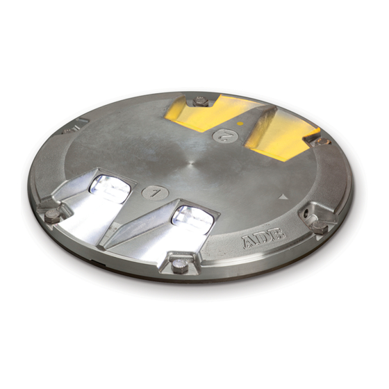
F-Range Type L-850C Style 3 Inset Lights Description Section 2 Description This section describes the ADB Airfield Solutions F-Range Type 1. Introduction L-850C, Style 3 inset lights. See Figures 2-1 and 2-2. The 12-inch L-850C F-Range inset light fixtures are designed to mark the runway edge. It is manufactured in accordance with FAA specification AC 150/5345-46B, Style 3 (... -
Page 14: Optical Unit
4. Light Channel 7. Lamp and Filter Holder Assembly 2. Top Cover 5. Lamp 8. Inner Cover 3. Prism 6. Optical Unit 9. Phillips Flat Head Screw Page 2-2 96A0285D 2006 ADB Airfield Solutions, Incorporated Issued 04/13 All rights reserved... -
Page 15: Figure 2-3 L-820C Optical Unit
Figure 2-3 L-820C Optical Unit 1. Grommet 4. Lockwasher 7. Filter 2. Bidirectional Optical Unit 5. Filter Spring 8. Unidirectional Optical Unit 3. Screw 6. Retainer Spring 9. Lamp Page 2-3 96A0285D 2006 ADB Airfield Solutions, Incorporated Issued 04/13 All rights reserved... -
Page 16: Inner Pan Subassembly
1. Fast-On Connectors 4. Pressure Release Screw 7. Wire Grommets 10. Cordset 2. Terminal Blocks 5. O-Ring 8. Wire Clamp 3. Cable Assembly 6. Inner Cover 9. Screw Page 2-4 96A0285D 2006 ADB Airfield Solutions, Incorporated Issued 04/13 All rights reserved... -
Page 17: Lamp And Filter Holder Assembly
Refer to Replacing Film Disc Cutout Assembly in the Repair section. CAUTION: Do not use a film disc cutout if circuit has monitoring. This will prevent the monitoring system from functioning properly. Page 2-5 96A0285D 2006 ADB Airfield Solutions, Incorporated Issued 04/13 All rights reserved... -
Page 18: Figure 2-5 One Lamp, Right Hand, With/Without Film Disc Cutout
Without Film Disc Cutout With Film Disc Cutout Figure 2-6 One Lamp, Left Hand, With/Without Film Disc Cutout Without Film Disc Cutout With Film Disc Cutout Page 2-6 96A0285D 2006 ADB Airfield Solutions, Incorporated Issued 04/13 All rights reserved... -
Page 19: Figure 2-7 Two Lamps, Two Cordsets, With/Without Film Disc Cutout
Figure 2-7 Two Lamps, Two Cordsets, With/Without Film Disc Cutout Without Film Disc Cutout With Film Disc Cutout Figure 2-8 Two Lamps, With/Without Film Disc Cutout Without Film Disc Cutout With Film Disc Cutout Page 2-7 96A0285D 2006 ADB Airfield Solutions, Incorporated Issued 04/13 All rights reserved... -
Page 20: F-Range L-850C Light Fixture: Required Equipment
Set of screwdrivers, one with 3/8 in. (9.525 mm) minimum blade width Silicone grease As required Joint sealing filler As required This subsection provides specifications for the F-Range L-850C inset 7. Specifications light fixtures. 105 W/6.6 A, MR16 lamp Lamp Refer to Table 2-3. -
Page 21: Rated Lamp Life
Refer below for the L-850C inset light dimensions in cardboard box. Dimensions 13 x 13 x 7 inches (330 x 330 x 180 mm) Weight of L-852 inset light is 12.3 lb (5.4 kg). Weight Page 2-9 96A0285D 2006 ADB Airfield Solutions, Incorporated Issued 04/13 All rights reserved... -
Page 22: Installation
The F-Range light fixture is designed for connection to a 6.6 A or 20 A 3. Input Requirement series lighting circuit via an L-830 isolation transformer. Refer to Summary Specifications in the Description section for required isolation transformers. Page 3-1 96A0285D 2006 ADB Airfield Solutions, Incorporated Issued 04/13 All rights reserved... -
Page 23: L-850C Toe-In Location Coding
NOTE: If dot labels are missing, the filter color can be determined by looking into the window to see the color of the filter installed. Figure 3-1 Installation of L-850C Light Fixture Orientation to Runway Centerline Page 3-2 96A0285D 2006 ADB Airfield Solutions, Incorporated Issued 04/13 All rights reserved... -
Page 24: Installation On L-868B Base
7. Isolation Transformer 10. Screw, 3/8 in. or M10 2. FAA Deep Base 5. Conduit 8. Ground Lug 3. Secondary Connectors 6. Spacer 9. Primary Connector Page 3-3 96A0285D 2006 ADB Airfield Solutions, Incorporated Issued 04/13 All rights reserved... - Page 25 Install the six bolts and lockwashers. Torque the bolts to 185 ±5 inch-pounds (20.902 ±0.565 Nt-M). Torque across the corners. Refer to Retorquing Mounting Bolts in the Maintenance section. Page 3-4 96A0285D 2006 ADB Airfield Solutions, Incorporated Issued 04/13 All rights reserved...
-
Page 26: Section 4 Maintenance
Check for damaged light fixtures. Replace damaged fixtures. Use a power broom for snow removal, if practical. Follow recommended snow removal techniques described in AC 150/5200-23. Page 4-1 96A0285D 2006 ADB Airfield Solutions, Incorporated Issued 04/13 All rights reserved... -
Page 27: Maintenance Procedures
To clean the light channel and prism, perform the following Cleaning Light Channel and procedure: Prism 1. See Figure 2-1. Use a suitable fiber brush to remove all accumulated debris from the light channel (4). Page 4-2 96A0285D 2006 ADB Airfield Solutions, Incorporated Issued 04/13 All rights reserved... -
Page 28: Retorquing Mounting Bolts
Wipe the holes clean with alcohol to remove all oil or diesel fuel and dirt. Clean with dry, oil-free, low-pressure air. Figure 4-1 Sequence for Torquing Mounting Bolts Page 4-3 96A0285D 2006 ADB Airfield Solutions, Incorporated Issued 04/13 All rights reserved... -
Page 29: Removing L-868 Base Water
Never hold the light fixture by the wires. This may damage the insulation, break the waterproof seal, and cause insulation faults and water leakage. Page 4-4 96A0285D 2006 ADB Airfield Solutions, Incorporated Issued 04/13 All rights reserved... -
Page 30: Testing For Leaks
(the opening created when the pressure release screw is removed). Screw fitting hand-tight. Figure 4-3 Pressure Test Fitting Assembly Pressure Test Fitting Lock Hose Plug Sleeve Page 4-5 96A0285D 2006 ADB Airfield Solutions, Incorporated Issued 04/13 All rights reserved... - Page 31 4 and 5. 7. See Figure 4-2. If leak is fixed, depressurize and reinstall the pressure release screw (E11). Page 4-6 96A0285D 2006 ADB Airfield Solutions, Incorporated Issued 04/13 All rights reserved...
-
Page 32: Introduction
This section contains troubleshooting information. This information 1. Introduction covers only the most common problems that you may encounter. If you cannot solve the problem with the information given here, contact your local ADB Airfield Solutions representative for help. Problem Page Lamp not energizing... -
Page 33: Troubleshooting Procedures
Damaged or missing lens seals or top Replace both lens seals. Replace top chamber cover O-ring cover O-ring. Cut or nick on L-823 cordset Replace insulation. insulation that exposes wire Page 5-2 96A0285D 2006 ADB Airfield Solutions, Incorporated Issued 04/13 All rights reserved... -
Page 34: Section 6 Repair
NOTE: Removing the pressure release screw equalizes the pressure inside and outside the fixture, making it easier to break the seal and remove the inner cover. Figure 6-1 Pressure Release Screw Page 6-1 96A0285D 2006 ADB Airfield Solutions, Incorporated Issued 04/13 All rights reserved... -
Page 35: Figure 6-2 Removing Screws
NOTE: The two recess slots are 180 degrees apart. Figure 6-3 Separating Inner Cover from Top Cover Page 6-2 96A0285D 2006 ADB Airfield Solutions, Incorporated Issued 04/13 All rights reserved... -
Page 36: Replacing Lamp And Filter
Item 4 on 63A0222 Grommet (for optical bracket) Figure 6-4 Item 5 on 7110.08.367 Screw, M4 x 10 (for optical bracket) Figure 6-4 Continued on next page Page 6-3 96A0285D 2006 ADB Airfield Solutions, Incorporated Issued 04/13 All rights reserved... - Page 37 NOTE C: Quantity is 1 for clear/yellow lens, 0 for clear/clear lens. To replace the lamp and filter, perform the following procedure: 1. Open the optical unit. Refer to Opening Optical Unit in this section. Page 6-4 96A0285D 2006 ADB Airfield Solutions, Incorporated Issued 04/13 All rights reserved...
-
Page 38: Figure 6-4 Removing Optical Unit From Inner Pan Assembly
2. See Figure 6-4. Lift the optical unit (1) from the inner pan 3. Replacing Lamp and assembly (2). Filter (contd.) Figure 6-4 Removing Optical Unit from Inner Pan Assembly Page 6-5 96A0285D 2006 ADB Airfield Solutions, Incorporated Issued 04/13 All rights reserved... -
Page 39: Figure 6-5 Inner Pan Assembly
September 20, 2006, perform the following procedure: a. While holding the reflector, unlatch the retainer spring (12). Figure 6-6 Old Lamp and Filter Holder Page 6-6 96A0285D 2006 ADB Airfield Solutions, Incorporated Issued 04/13 All rights reserved... -
Page 40: Figure 6-7 Arrow Pointing Up
Put the filter spring back in. Make sure the curved part of the filter spring faces the filter. e. Put the two parts of the retainer spring in their respective notches on the lamp and filter holder assembly. Page 6-7 96A0285D 2006 ADB Airfield Solutions, Incorporated Issued 04/13 All rights reserved... -
Page 41: Figure 6-8 New Lamp And Filter Holder
Never touch the bulb of the lamp with your bare hands. It will reduce the lifetime of the lamp considerably. Should it happen, clean the bulb with alcohol. Page 6-8 96A0285D 2006 ADB Airfield Solutions, Incorporated Issued 04/13 All rights reserved... -
Page 42: Replacing Film Disc Cutout Assembly
Film disc cutout See note. 4071.50.130 Film disc cutout clip See note. 7110.08.367 Spring clip screw See note. NOTE A: Quantity is 1 for unidirectional, 2 for bidirectional. Page 6-9 96A0285D 2006 ADB Airfield Solutions, Incorporated Issued 04/13 All rights reserved... -
Page 43: Figure 6-9 Disconnecting Lamp Wiring From Terminals
Figure 6-9 Disconnecting Lamp Wiring from Terminals 3. See Figure 6-4. Grasp the optical unit (1) and pull straight up from the inner pan assembly (2). Page 6-10 96A0285D 2006 ADB Airfield Solutions, Incorporated Issued 04/13 All rights reserved... -
Page 44: Figure 6-10 Film Disc Cutout Assembly And Optical Unit
6. Reassemble all components in reverse order as removal. The inner pan assembly is now ready to reinstall on the top cover. Page 6-11 96A0285D 2006 ADB Airfield Solutions, Incorporated Issued 04/13 All rights reserved... -
Page 45: Replacing Prism
NOTE B: Quantity is 2 for unidirectional, 4 for bidirectional. To replace the prism, perform the following procedure: 1. See Figure 6-11. Remove the prism-clamp plate (B6) secured in the cover. Figure 6-11 Replacing Prism Page 6-12 96A0285D 2006 ADB Airfield Solutions, Incorporated Issued 04/13 All rights reserved... -
Page 46: Replacing Optical Unit
“THIS SIDE UP”. 4. Torque the fixing screws to 3.5 0.5 Nt-m (31 4 inch-pounds). Page 6-13 96A0285D 2006 ADB Airfield Solutions, Incorporated Issued 04/13 All rights reserved... -
Page 47: Replacing L-823 Cordset
1. Open the optical unit. Refer to Opening Optical Unit in this section. 2. Remove the optical unit. Refer to Replacing Optical Unit in this section. Page 6-14 96A0285D 2006 ADB Airfield Solutions, Incorporated Issued 04/13 All rights reserved... -
Page 48: Figure 6-12 L-823 Cordset
11. Crimp on the new fast-on connectors and connect them to the terminals. Adjust the wires inside the inner cover. 12. Torque the screws (F7) to 31 4 inch-pounds (3.5 0.5 Nt-m). Page 6-15 96A0285D 2006 ADB Airfield Solutions, Incorporated Issued 04/13 All rights reserved... -
Page 49: Closing Optical Unit
Inner cover (of inner pan assembly) 64A0925-10 Screw, M5 x 10 NOTE A: Quantity is 1 for unidirectional, 2 for bidirectional. NOTE B: Quantity is 2 for unidirectional, 4 for bidirectional. Page 6-16 96A0285D 2006 ADB Airfield Solutions, Incorporated Issued 04/13 All rights reserved... -
Page 50: Figure 6-13 L-850C Inset Light Fixture
To close the optical unit, perform the following procedure: 8. Closing Optical Unit (contd.) 1. See Figure 6-13. Turn the top cover (2) upside down. Figure 6-13 L-850C Inset Light Fixture Page 6-17 96A0285D 2006 ADB Airfield Solutions, Incorporated Issued 04/13 All rights reserved... - Page 51 20 psi. Refer to Testing for Leaks in the Maintenance section. 9. Make sure the O-ring seal for the pressure release screw is in good condition and reinstall the pressure release screw. Page 6-18 96A0285D 2006 ADB Airfield Solutions, Incorporated Issued 04/13 All rights reserved...
-
Page 52: Section 7 Parts
F-Range Type L-850C Style 3 Inset Lights Parts Section 7 Parts To order parts, call ADB Airfield Solutions Customer Service or your 1. Introduction local representative. Use this four-column parts list, and the accompanying illustration, to describe and locate parts correctly. -
Page 53: F-Range L-850C Light Fixture Part Numbering System
0 = White (No Filter) 1 = Yellow Left Filter Colors 0 = White (No Filter) 1 = Yellow Figure 7-1 L-850C F-Range Inset Lights Part Number Page 7-2 96A0285D 2006 ADB Airfield Solutions, Incorporated Issued 04/13 All rights reserved... -
Page 54: F-Range L-850C Light Fixture Parts List
NOTE A: Quantity is 1 for unidirectional, 2 for bidirectional. NOTE B: Quantity is 1 for clear/yellow lens, 0 for clear/clear lens. The white lens has no filter. Continued on next page Page 7-3 96A0285D 2006 ADB Airfield Solutions, Incorporated Issued 04/13 All rights reserved... - Page 55 7284.10.416 Spring lockwasher, M4 See note. NOTE A: Quantity is 1 for unidirectional, 2 for bidirectional. NOTE B: Quantity is 2 for unidirectional, 4 for bidirectional. Page 7-4 96A0285D 2006 ADB Airfield Solutions, Incorporated Issued 04/13 All rights reserved...
-
Page 56: Figure 7-2 F-Range L-850C Light Fixture (1 Of 3)
44A6017 708.90.710 4071.50.030 64A0936-13 63A0964 4071.58.510 1411.22.001 1411.22.002 4071.50.160 2990.40.900 44A6018 7110.08.367 7284.10.416 63A0222 60A2603 44A6019 64A0925-10 Figure 7-2 F-Range L-850C Light Fixture (1 of 3) Page 7-5 96A0285D 2006 ADB Airfield Solutions, Incorporated Issued 04/13 All rights reserved... - Page 57 Parts 7110.08.367 4071.50.090 73A0133-31 6126.01.031 44A6017 4071.50.090 60A2602 63B0267-011 7110.08.367 Figure 7-2. F-Range L-850C Light Fixture (2 of 3) 4017.50.130 6111.87.140 44A6112 47A0118 44A6112 7110.08.367 Figure 7-2. F-Range L-850C Light Fixture (3 of 3) Page 7-6 96A0285D 2006 ADB Airfield Solutions, Incorporated...
-
Page 58: F-Range Optical Unit Parts List
7284.10.416 Spring lockwasher, M4 See note. NOTE A: Quantity is 1 for unidirectional, 2 for bidirectional. NOTE B: Quantity is 2 for unidirectional, 4 for bidirectional. Page 7-7 96A0285D 2006 ADB Airfield Solutions, Incorporated Issued 04/13 All rights reserved... -
Page 59: Recommended Spare Parts
Film disc cutout 60A2602 Pressure release screw 60A2603 Optical bracket 63A0222 Grommet (for optical bracket) 63A0964 Filter, yellow 63A0986 Flat seal 63A0993-3 Prism Continued on next page Page 7-8 96A0285D 2006 ADB Airfield Solutions, Incorporated Issued 04/13 All rights reserved... - Page 60 Screw, M4 x 10 (for optical bracket) Screw, M4 x 10 (for cordset) Screw, M4 x 10 (spring clipscrew for film disc cutout ) 7284.10.416 Spring lockwasher, M4 Page 7-9 96A0285D 2006 ADB Airfield Solutions, Incorporated Issued 04/13 All rights reserved...
Need help?
Do you have a question about the F-Range L-850C and is the answer not in the manual?
Questions and answers