
Related Manuals for ADB EURODIM Twin Tech


Summary of Contents for ADB EURODIM Twin Tech
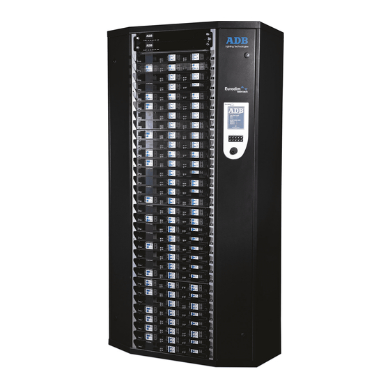
- Page 1 EURODIM Twin Tech Installation Manual V 1.2 Lighting Technologies M 3213 1106.03.213...
-
Page 3: Table Of Contents
EURODIM TWIN TECH INDEX DELIVERY - UNPACKING ......................3 DESCRIPTION ..........................4 INSTALLATION ..........................5 Dimmer room ......................... 5 3.1.1 Preparation ........................5 Ventilation of the dimmer room....................6 3.2.1 Example No. 1 ........................6 Installation of the cabinets ..................... 7 3.3.1... - Page 4 Example 5: Two DMX lighting desks, two CPU’S per EURODIM cabinet (case B) .... 40 10.5 Appendix B – Drawings ......................41 5000-35-650 EURODIM Twin Tech – Vertical Packaging (standard) ......... 41 11.1 11.2 3500.01.650 Power Modules 1 - 8 ..................42 11.3...
-
Page 5: Delivery - Unpacking
Do not attempt installation unless you are suitably qualified. Installation errors may endanger operators and cause system damage and failure. If you do not understand a point in this manual, don’t guess. Contact ADB or one of our authorised distribution partners for advice. -
Page 6: Description
EURODIM TWIN TECH 2. DESCRIPTION www.adblighting.com Installation manual - Page 4 Version 1.2... -
Page 7: Installation
3.1 Dimmer room 3.1.1 Preparation Determine the dimensions of the dimmer room so as to place all EURODIM Twin Tech cabinets easily. Provide for an open space of approximately 90 cm in front of the cabinets to facilitate maintenance. Before attempting to move the rack(s) into the final position, check access routes to the dimmer room for space to manoeuvre through doorways and around corridor corners. -
Page 8: Ventilation Of The Dimmer Room
40% are off. 3.2.1 Example No. 1 A dimmer room with a EURODIM Twin Tech cabinet equipped with 128 thyristor dimmers of 3 kW and a second cabinet with 96 thyristor dimmers of 5 kW. The cabinets are fitted with a back-up power supply for the processor unit. -
Page 9: Installation Of The Cabinets
1,5 Nm Metric Wrench 7 Helical Spring Lock each) Washers M 4 Hex Cap Screw Junction Plate 3 Nm Metric Wrenches 24 (Accessory) M 16 x 25 ADB recommend using Insulated Screwdriver. www.adblighting.com Installation manual - Page 7 Version 1.2... -
Page 10: Packaging
EURODIM TWIN TECH 3.3.2 Packaging The cabinets are shipped on a wooden pallet (see attached drawing in Chapter 12: 5000-35-650). Standard transport position is vertical; First open the top panel after removing the screws of the side panels. The control processors, TTD Human Interface and dimmer modules are packed separately. - Page 11 EURODIM TWIN TECH The weight and dimensions of the cabinets are included in Chapter “Characteristics”. Prior to positioning each cabinet, ensure that the floor is flat and horizontal to ensure a good weight distribution. It is the responsibility of the system integrator or installer to check if the cabinet weight load...
-
Page 12: Contractor's Compartment - Supply
EURODIM TWIN TECH 4. CONTRACTOR'S COMPARTMENT – SUPPLY Front access only is required. Cable entry is possible through bottom and top of the cabinet. Cover panels for the unused cable entry/ exit apertures are supplied. In order to gain maximum space to access the... -
Page 13: Controller Electronics - Cpu/ Psu Crate
EURODIM TWIN TECH 4.1 Controller Electronics - CPU/ PSU crate The CPU/ PSU crate is already mounted in our factory. If a removal is required, loosen the 4 screws and remove the complete crate gently. Replace the connected flat cables with caution. -
Page 14: Supply Busbar
EURODIM TWIN TECH 4.3 Supply busbar The three phase connection points are labelled L1 (phase No. 1, phase R), L2 (phase No. 2, phase S) and L3 (phase No. 3, phase T). The Neutral is labelled N and the colour code for the Neutral is blue, as per IEC Recommendation 446. -
Page 15: Protected Earth (Pe)
EURODIM TWIN TECH 4.3.1 Protected Earth (PE) The Protective Earth (PE) on the busbar connection is a bolt and nut, size M10. Colour code: green/yellow. The equipotential connection, connecting the metal frame, is provided at the top of the supply cabling compartment. This connection is already wired to the busbar PE. -
Page 16: Ground And Earth Connections
EURODIM TWIN TECH 4.5 Ground and Earth Connections The sound or video earth should be separated from the dimmer earth. The distance between the dimmer earth and the others should be as large as possible. Refer to local regulations for grounding. -
Page 17: Sequential Diagnostics (Optional)
Human Interface or a remote program running the TTD Management Software. The communication to a single remote reporting pc is done via the proprietary ADB ADN protocol based on an Ethernet Network to a Personal Computer with the Windows Operating System running the TTD Management Software. -
Page 18: Hardware Installation
All the hardware installations are to be performed in the left hand contractor department. This is where the EURODIM Twin Tech cabinet receives the power supply. It is advisable to mount the hardware before you introduce the power supply cables, because there is more space for the installation left. -
Page 19: Mounting Procedure
EURODIM TWIN TECH 5.2 Mounting Procedure PCB 3015 Connector (the other connectors remain as they are for fan power). Figure 1: open TI before mounting Detail of Mounting Place for PCB 3015 (Cable for connection to PCB 3015) Cables from TI 5.3 Finished installation... -
Page 20: Software Installation
5.4 Software Installation The black lines are ETHERNET connections between the EURODIM Twin Tech, Switch and PC running the TTD Management Software. This software must only be installed one time. At the same time a lighting control desk (which must support ArtNET communications protocol) may be connected to the ETHERNET Switch. - Page 21 ETHERNET Switch ……. Multiple EURODIM Twin Tech Cabinets (TTD) – The ETHERNET cable is connected on the controls input board. The Diagnostics Information is transported over the same physical wire as the ArtNET signal. The report information is transported to the TT Management Software by the ADB proprietary protocol ADN.
-
Page 22: Overview Of The User Interface Menu Items
Below are screen shots of the local menu items, when addressing the Scan Load Function on the EURODIM Twin Tech itself. – When the Scan Load sequence is started the dimmer steps through all enabled channels. On the display (after the scan) the unit reports if there any differences to a pre-defined or measured value. -
Page 23: Ttd Management Software
EURODIM TWIN TECH 5.6 TTD Management SOFTWARE To remote control the EURODIM Twin Tech from a central control room ADB provides as an option the TTD Management Software. This software tool is designed to run on Window OS (32 Bit) and is optionally available. Only one TTD Management software licence is necessary per site. -
Page 24: References And Element Codes
EURODIM TWIN TECH 5.7 References and Element Codes Sequential Diagnostics Kit (optional) consisting of: o Kit PCB3015 o Fixation : N1115.04.420 o PCB3015 : 1131.44.001 with two screws to mount the PCB in the cabinet ADB Code: ADB REF: TTD/SEQD PYRE DESCRIPTION: Sequential Diagnostics –... -
Page 25: Contractor's Compartment - Outputs
EURODIM TWIN TECH 6. CONTRACTOR’S COMPARTMENT – OUTPUTS Front access only is required. Cable entry is possible through bottom and top of the cabinet. BACK: ODD NUMBERED MODULES 1.1 – 1.4 (L1) FRONT: MODULE 15 (L3) EVEN NUMBERED LINE 15.1... -
Page 26: Outputs To The Loads
EURODIM TWIN TECH 6.1 Outputs to the loads The cabling compartment with output terminals is on the right hand side. The load terminals are mounted next to the relevant module. The numbering is shown on self-adhesive labels. These terminal blocks are suitable for cable sizes up to 10 mm². Special Adaptors are available for cables up to 25 mm²... -
Page 27: Load Terminals For 10Kw Modules
EURODIM TWIN TECH Tripping the MCB of a fluo dimmer will disconnect the dimmer and its associated direct output. The direct output can be patched to an independent DMX channel. Please also see attached drawing N° 3500.01.710 6.6 Load terminals for 10kW modules Each 10 kW module is shipped with a special adaptor allowing the user to connect cables with up to 25mm²... -
Page 28: Dmx And Ethernet Terminals
UTP = unshielded twisted pair. WARNING: UTP Ethernet cable is not suitable for DMX. Each EURODIM Twin Tech processor is equipped with two physical DMX inputs, and one Ethernet port. For cabinets with optional ‘instant back-up’, each processor has its own independent data connectors. -
Page 29: Pin Numbering
EURODIM TWIN TECH Screw connector in parallel with RJ45-for-DMX For the convenience of the contractor, each physical DMX input has two types of connector in parallel: a pluggable screw terminal block, and a RJ45. Use one, never use both. The RJ45 are very convenient to use off-the-shelf STP cables for daisy-chaining between dimmer cabinets, and connection to RJ45 DMX patchfields. -
Page 30: Local / Remote Controller Selector Switch Cpu1 - Cpu2 - Automatic
EURODIM TWIN TECH 6.7 Local / Remote Controller selector switch CPU1 – CPU2 – Automatic The Controller or CPU selector switch is located next the CPU slots. connection for the remote selector switch is provided in the right compartment on the PCB 3031. -
Page 31: Ttd Human Interface
The TTD Human Interface is found in a separate packing. In case such a unit has to be reordered the ADB code Nr is: 1115.10.055. The package includes the TTD HUMAN INTERFACE with a mounted metal back part, one connection cable, and one SD card (mounted in the HUMAN INTERFACE) and one EURODIM Twin Tech user and programming manual in English and French. - Page 32 EURODIM TWIN TECH Figure 2: Human Interface Installed - SD Card Slot towards front www.adblighting.com Installation manual - Page 30 Version 1.2...
-
Page 33: Plug In Modules
The Module number appears on the right of the module. 8.6 Protections – types, number of poles EURODIM Twin Tech is a standard cabinet to suit all installation types (IEC 60364). All configurations relay on the used plug in modules. -
Page 34: Dimmer Module Protection By Hrc Fuse
Additionally, the breaking of the contacts is sequential: first control, then power, and Earth last. ADB has taken precautions that there is a minimal impact in case this rule is forgotten. When a module is plugged into the cabinet – first the protection earth is connected, then the supply and load supplies are connected and finally the control wiring connection is performed. -
Page 35: Installing Dimmer Modules
EURODIM TWIN TECH 8.10 Installing Dimmer Modules When inserting dimmer modules in to the crate please do so carefully. If the modules are forced into the crate, the connectors on the back may be damaged, or in the worst case the backplane PCB of the dimmer cabinet is damaged. -
Page 36: Controller Unit (Cpu) - Power Supply Unit (Psu)
8.11 CONTROLLER UNIT (CPU) - POWER SUPPLY UNIT (PSU) Ordering EURODIM Twin Tech you have the choice to either configure the cabinet with 2 identical Controller units for full data and power backup or 1 Controller (CPU) unit + 1 PSU unit for power supply backup. -
Page 37: Blank Modules
EURODIM TWIN TECH 8.12 BLANK MODULES Empty dimmer slots shall be filled with blank panels. Two versions are available: TTD/TB Blank modules for one slot: blank modules must screwed on each side to the module rack. Open the two doors and use the delivered screws at the assigned drill holes. -
Page 38: Module Locks
8.13 MODULE LOCKS A set of two bars are optionally available. (ADB REF: TTD/CAB/LOCK, ADB Code: 1113.33.010). These are intended to be used a locks for the modules, to avoid physical tampering with the configuration of the dimmer and the placement of the modules. The bars must be screwed on the left hand side of dimmer. -
Page 39: Characteristics
EURODIM TWIN TECH 9. CHARACTERISTICS 9.1 Electrical characteristics Supply voltage: 3 NPE 400 TN-S or TN-C Operating voltage: 198 V to 264 V, 50/60 Hz. Max line current: 600 A per phase 600 A for the Neutral (due to the possibility of unbalanced 3phase system, the neutral... -
Page 40: Physical Characteristics
EURODIM TWIN TECH 9.2 Physical characteristics EURODIM TWIN TECH for 32 modules Dimensions Width: 990 mm Depth: 596 mm Height: 1999 mm. Weight: Cabinet: 229 kg (without modules nor processors) Processor unit: 10 kg Thyristor module 4 x 3 kW – 12.2 kg for 400μs/ 9.5 kg for 200μs Thyristor module 3 x 5 kW 10.9 kg for 400μs/ 9,3 kg for 200μs... -
Page 41: Dmx Network And Interconnetcions
EURODIM TWIN TECH 10. DMX NETWORK AND INTERCONNETCIONS 10.1 Example 1: 10.2 Example 2: One DMX lighting desk, two CPU’s One DMX lighting desk, one CPU per EURODIM cabinet per EURODIM cabinet DMX SOURCE No. 1 DMX SOURCE No. 1 (e.g. - Page 42 EURODIM TWIN TECH 10.4 Example 4: 10.5 Example 5: Two DMX lighting desks, two Two DMX lighting desks, two CPU’s per EURODIM cabinet CPU’S per EURODIM cabinet (case A) (case B) DMX SOURCE No. 1 DMX SOURCE No. 2 DMX SOURCE No. 1 DMX SOURCE No.
-
Page 43: Appendix B - Drawings
EURODIM TWIN TECH 11. Appendix B – Drawings 11.1 5000-35-650 EURODIM Twin Tech – Vertical Packaging (standard) www.adblighting.com Installation manual - Page 41 Version 1.2... -
Page 44: 3500.01.650 Power Modules 1 - 8
EURODIM TWIN TECH 11.2 3500.01.650 Power Modules 1 - 8 www.adblighting.com Installation manual - Page 42 Version 1.2... -
Page 45: 3500.01.660 Power Modules 9 - 16
EURODIM TWIN TECH 11.3 3500.01.660 Power Modules 9 - 16 www.adblighting.com Installation manual - Page 43 Version 1.2... -
Page 46: 3500.01.670 Power Modules 17 - 24
EURODIM TWIN TECH 11.4 3500.01.670 Power Modules 17 - 24 www.adblighting.com Installation manual - Page 44 Version 1.2... -
Page 47: 3500.01.680 Power Modules 25 - 32
EURODIM TWIN TECH 11.5 3500.01.680 Power Modules 25 - 32 www.adblighting.com Installation manual - Page 45 Version 1.2... -
Page 48: Kw Module Connection
EURODIM TWIN TECH 11.6 10 kW Module Connection www.adblighting.com Installation manual - Page 46 Version 1.2... -
Page 49: 3650.00.311 Pcb3031 Dmx512 Connection
EURODIM TWIN TECH 11.7 3650.00.311 PCB3031 DMX512 Connection www.adblighting.com Installation manual - Page 47 Version 1.2... -
Page 50: 3650.00.311 Pcb3031 Selector With Wiring
EURODIM TWIN TECH 11.8 3650.00.311 PCB3031 Selector with Wiring www.adblighting.com Installation manual - Page 48 Version 1.2... -
Page 51: 3500.01.710 Output Terminals For Fluo Modules
EURODIM TWIN TECH 11.9 3500.01.710 OUTPUT TERMINALS FOR FLUO Modules www.adblighting.com Installation manual - Page 49 Version 1.2... -
Page 52: Ce Certificate For Eurodim Twin Tech
EURODIM TWIN TECH 11.10 CE Certificate for EURODIM Twin Tech www.adblighting.com Installation manual - Page 50 Version 1.2... -
Page 53: Appendix C- Power Supply For Thyristor Dimmers - Basic Principles For Safe Electrical Design
EURODIM TWIN TECH 12. Appendix C– Power Supply for Thyristor Dimmers – Basic Principles for Safe Electrical Design The global performance of a dimmer system depends on the dimmers and also on its electrical supply system: supply transformer, supply cabling to the dimmers. Planners and... -
Page 54: Current In The Neutral - Dimmer Systems
125% in the Neutral – how can I see this for myself? You can see this with a simple set-up which requires only basic equipment: - any 3-phase dimmer, e.g. an ADB MEMOPACK or MICROPACK, connected to a three- phase star supply (3P+N+E) - three identical lamp loads e.g. -
Page 55: Main Transformer, Cables, Switchgear, Busbar Systems
EURODIM TWIN TECH 12.6 Main transformer, cables, switchgear, busbar systems The main transformer, the switchgear and the supply cables to the dimmer cabinet carry these non-sinusoidal currents. This is valid for all phase-control dimmers (thyristor, triac, and some transistor dimmers), independent of brand and manufacturer. -
Page 56: Appendix D: Specification Of Magnetic Circuit Breakers (Mcb)
In this chapter we would like to discuss the dimension and types of MCB used for our dimmers. For 3 kW circuits ADB uses 13 A and for 5 kW circuits 20 A rated MCB with C Curve. Below we will explain why we use these values; it has been carefully designed in our product, for your maximum safety and protection. - Page 57 EURODIM TWIN TECH 14. CONFIGURATION TABLES EURODIM TWIN TECH CABINET / VERSION WITH 32 MODULES TYPE PHASE MODULE ADB ID USER ID (eg. outlet number) CABLE TYPE www.adblighting.com Installation manual - Page 55 Version 1.2...
- Page 58 EURODIM TWIN TECH TYPE PHASE MODULE ADB ID USER ID (eg. outlet number) CABLE TYPE 10.1 10.2 10.3 10.4 11.1 11.2 11.3 11.4 12.1 12.2 12.3 12.4 13.1 13.2 13.3 13.4 14.1 14.2 14.3 14.4 15.1 15.2 15.3 15.4 16.1 16.2...
- Page 59 EURODIM TWIN TECH TYPE PHASE MODULE ADB ID USER ID (eg. outlet number) CABLE TYPE 17.1 17.2 17.3 17.4 18.1 18.2 18.3 18.4 19.1 19.2 19.3 19.4 20.1 20.2 20.3 20.4 21.1 21.2 21.3 21.4 22.1 22.2 22.3 22.4 23.1 23.2...
- Page 60 EURODIM TWIN TECH TYPE PHASE MODULE ADB ID USER ID (eg. outlet number) CABLE TYPE 25.1 25.2 25.3 25.4 26.1 26.2 26.3 26.4 27.1 27.2 27.3 27.4 28.1 28.2 28.3 28.4 29.1 29.2 29.3 29.4 30.1 30.2 30.3 30.4 31.1 31.2...
- Page 61 EURODIM TWIN TECH Notes www.adblighting.com Installation manual - Page 59 Version 1.2...
- Page 62 EURODIM TWIN TECH Notes www.adblighting.com Installation manual - Page 60 Version 1.2...
- Page 64 ADB - Your Partner for Light Belgium N.V. ADB-TTV Technologies S.A. (Group Headquarters) Leuvensesteenweg 585, B-1930 Zaventem Tel : +32.2.709.32.11, Fax : +32.2.709.32.80, E-Mail : adb@adblighting.com France ADB S.A.S. Sales Office: 92, Avenue Jean Jaurès F-92120 Montrouge Tel : +33.1.41.17.48.50, Fax : +33.1.42.53.54.76, E-Mail : adb.fr@adblighting.com Factory &...
- Page 65 EURODIM Twin Tech Quick Start Guide Issue 1.0 Lighting Technologies SF 3213 1106.03.213...
- Page 67 Dimmer Room ........................... 2 Preparation ........................2 Ventilation of the Dimmer Room ..................2 Example ......................... 2 1.2.1 Installation of the Cabinets ....................3 Tools for commissioning ....................3 1.3.1 Description of the Unit ......................4 Contractor's Compartment – Supply ................. 4 2.1.1 Supply voltage .......................
-
Page 68: Dimmer Room
40% are off. 1.2.1 Example A dimmer room with a EURODIM TWIN TECH cabinet equipped with 128 thyristor dimmers of 3 kW and a second cabinet with 96 thyristor dimmers of 5 kW. The cabinets are fitted with a back-up power supply for the processor unit. -
Page 69: Tools For Commissioning
Cabinet N°2 Electronics: 1 x 150 W Dimmers 96 x 69 W x 0.6 = 3974 W ROOM TOTAL: 7115 W (1 W = 0.86 kcal/hour) or 6119 kcal/hour. In this example, it will be necessary to evacuate approximately 7115 W of losses. Installation of the Cabinets 1.3.1 Tools for commissioning Operation... -
Page 70: Description Of The Unit
2. Description of the Unit 2.1 Contractor's Compartment – Supply Front access only is required. Cable entry is possible through bottom and top of the cabinet. Cover panels for the unused cable entry/ exit apertures are supplied. In order to gain maximum space to access the cabinet for installation and maintenance purposes, remove the two doors, loosen the 16 crosshead screws in the back and 3 left +... -
Page 71: Supply Voltage
2.1.1 Supply voltage The high voltage/low voltage power transformer MUST ABSOLUTELY provide a three phase star system with available neutral (3NPE-400), and rated line voltage 380 V to 415 V between phases and 220 V to 240 V rated voltage between each phase and neutral. -
Page 72: Protected Earth (Pe)
2.1.3 Protected Earth (PE) The Protective Earth (PE) on the busbar connection is a bolt and nut, size M10. Colour code: green/yellow. equipotential connection, connecting the metal frame, is provided at the top of the supply cabling compartment. This connection already wired to the busbar PE. -
Page 73: Contractor"S Compartment - Outputs
2.2 Contractor’s Compartment – Outputs Front access only is required. Cable entry is possible through bottom and top of the cabinet. BACK: ODD NUMBERED MODULES 1.1 – 1.4 (L1) FRONT: MODULE 15 (L3) EVEN NUMBERED LINE 15.1 MODULES NEUTRAL 2.1 - 2.4 (L2) LINE 15.2 NEUTRAL... -
Page 74: Outputs To The Loads
2.2.1 Outputs to the loads The cabling compartment with output terminals is on the right hand side. The load terminals are mounted next to the relevant module. The numbering is shown on self- adhesive labels. These terminal blocks are suitable for cable sizes up to 10 mm². Adaptors are available for cables up to 25 mm². -
Page 75: Pin Numbering
Each EURODIM TWIN TECH processor is equipped with two physical DMX inputs, and one Ethernet port. For cabinets with optional „instant back-up‟, each processor has its own independent data connectors. 2.2.4 Pin numbering For standard DMX cables (2 pairs + screen), the connectors X1 through X8 are connected... -
Page 76: Local / Remote Selector Switch Cpu1 - Cpu2 - Automatic
2.2.6 Local / Remote selector switch CPU1 – CPU2 – Automatic The CPU selector switch is located next to the CPU slots. The connection for the remote selector switch is provided in the right compartment on the PCB 3031. Please see the attached drawing for the exact wiring of the switch. -
Page 77: Power Module Example
2.4 Central Prosessor Unit (CPU) - Power Supply Unit (PSU) Ordering EURODIM TWIN TECH you have the choice to either configure the cabinet with 2 identical CPU units for full data and power backup or 1 CPU unit + 1 PSU unit for power supply backup. -
Page 78: The Human Machine Interface
The TTD Human Interface is found in a separate packing. In case such a unit has to be reordered the ADB code Nr is: 1115.10.055. The package includes the TTD HUMAN INTERFACE with a mounted metal back part, one connection cable, one SD card (mounted in HUMAN INTERFACE) and one EURODIM Twin Tech user and programming manual in English and French. -
Page 79: Using The Ttd Human Interface (Hmi)
When the right-hand side door of the cabinet is opened, the rear of the Unit gives access to the following: 1 - An opening on the rear face to activate the software reset button (in the event that the touch screen becomes blocked) 2 - An opening in the side face for insertion of the SD memory card 3 - A connector to link up to the Twin Tech cabinet Controller units. -
Page 80: Accessing The Ttd Human Interface (Hmi)
Manually synchronise between controllers ADB service Level 0 does not allow access to any menu or function. Depending on the authorised access level, certain functions or menus remain blocked. Should you attempt to access these, the software will ask you to enter the access code for the next level in order to authorise access to the function or menu. -
Page 81: Screensaver
4. Screensaver If whilst accessing a screen page other than the home page, the user does not handle the touch-screen, keyboard or wheel for a period of more than one minute, the software returns to the home page. The access code will become 0. To access the "Menu" screen pages, an access code will again need to be entered. -
Page 82: Online Assistance
5. Online Assistance A "HELP" key is provided in the bottom right-hand corner of all of the screen pages, allowing touch-access to a help function, relating to the page consulted. Press the “BACK” touch-button to return to the screen page. www.adblighting.com Quick Start - page 16 Issue 1.0... -
Page 83: Menu Tree-Structure
6. Menu Tree-Structure www.adblighting.com Quick Start - page 17 Issue 1.0... -
Page 84: Cabinet Configuration
7. Cabinet Configuration The upper part of the Twin Tech cabinet may be equipped with: Two Controller units, or a Controller unit and a backup power supply module. The Controller units, control all of the circuits (128 max.) constituting the modules available in the cabinet (32 max.), according to the configuration recorded by the Unit software (patch) and the channel values present on the DMX A, DMX B and ARTNET inputs (ETHERNET connection). -
Page 85: Module Control
Module Control The selector allows the Controller unit in service to be chosen. It may be set to position 1, A/R or 2. When a controller is selected (1 or 2), the DMX A, DMX B and ARTNET signals present at this controller‟s input are used. -
Page 86: Presentation Of The Home Page
8. Presentation of the Home Page This screen page is displayed as soon as the cabinet is switched on. It gives the information concerning the start address for the DMX A and B inputs and the three ARTNET universes. Information available for start address (valid for DMX and ARTNET): ... -
Page 87: Presentation Of The Cabinet Diagnostic Page
9. Presentation of the Cabinet Diagnostic Page This screen shows the cabinet diagnostic information. This page is divided into three zones: A zone (CTRL1 or CRTL2 tab) providing information on the controllers, A zone (EURODIM TT INFO) providing general information on the cabinet‟s operation, identification of the modules by the controller and signalling the alarms, ... - Page 88 Hardware/communication: • "OK" if the controller is operating correctly, • "Not OK" if a problem is detected. In this case, an error message and an exclamation mark appear in the EURODIM TT INFO zone. Software version: software version present in the controller Temperature: •...
-
Page 89: Description Of The Menus
View ARTNET: general information on the ARTNET universes and the Ethernet connection ARTNET set.: to configure the three ARTNET universes ADB Service: function available to ADB technical service only Synchro: to synchronise the parameters recorded between each of the controllers www.adblighting.com Quick Start - page 23... - Page 90 Note: All the information displayed in the different menus originates from controller 1 if two controllers are present in the cabinet. If only controller 2 is present, all the information displayed in the different menus will originate from the latter. When changing the patch, power multiplication factor, law...
-
Page 91: Patch Menu
11. Patch Menu This function is used to configure a patch on a circuit or set of circuits for the DMX A and DMX B signal. This configuration enables the user to attribute the value of a DMX A and DMX B signal channel to the control of one of the cabinet‟s circuits. - Page 92 Important: Specific case for row 1/1: if key 0 or 1 is used, the value taken into consideration corresponds to the content of output 128 if available, otherwise output 127, and so on. If the value entered is 0 or greater than 512, the circuit is not controllable and the message "Not used"...
-
Page 93: Artnet Patch Menu
12. ARTNET Patch Menu This function is used to configure a patch on a circuit or a set of circuits for each of universes 1, 2 and 3. This configuration is used to attribute the value of a channel of each universe to the control of a circuit of the cabinet. -
Page 94: Range Key
Start by selecting universe 1, 2 or 3. Use the wheel to rapidly move between all the rows of the patch. The row selected is highlighted. To attribute a channel, position on a row and use: The touch-screen and the numeric keyboard to enter a value, ... -
Page 95: Artnet Info Menu
13. ARTNET Info Menu These two screens show the status of the ARTNET connections, the configuration information for the three universes managed by each controller, as well as the IP addresses entered at each controller. To Dock a window: This page is divided into two zones: ... - Page 96 Subnet: value between 0 and 15, see "ARTNET config" menu Port: value between 0 and 15, see "ARTNET config" menu Note: When the ARTNET entries are controlled by an ISIS rotating ADB console, all the subnets must have the same number.
-
Page 97: Artnet Configuration Menu
14. ARTNET Configuration Menu This function configures the ARTNET universes for the two controllers as well as the subnet and port values. 14.1 Selecting Universe Mode For each universe, choose the operating mode: “Not Used” mode: the universe is not taken into consideration for the control of the circuits, “ARTNET”... - Page 98 Personal Notes www.adblighting.com Quick Start - page 32 Issue 1.0...
- Page 100 ADB - Your Partner for Light Belgium N.V. ADB-TTV Technologies S.A. (Group Headquarters) Leuvensesteenweg 585, B-1930 Zaventem Tel : +32.2.709.32.11, Fax : +32.2.709.32.80, E-Mail : adb@adblighting.com France ADB S.A.S. Sales Office: 92, Avenue Jean Jaurès F-92120 Montrouge Tel : +33.1.41.17.48.50, Fax : +33.1.42.53.54.76, E-Mail : adb.fr@adblighting.com Factory &...
- Page 101 EURODIM Twin Tech User Manual V 1.1 Lighting Technologies M 3213 1106.53.213...
- Page 103 Presentation of the Cabinet Diagnostic Page ..............14 12.1 Controller (CTRL) Information ..................14 12.2 EURODIM Twin Tech Information ................15 12.3 DMX Information ......................15 Presentation of the ARTNET Information Page ............... 16 Description of the Menus ....................17 Patch Menu.........................
- Page 104 Managing the Alarms ......................58 39.1 Errors List Screen Page ....................59 39.2 List of Errors displayed in the EURODIM Twin Tech Frame ........60 39.3 List of Errors displayed in the CTRL Board Frame ............60 39.4 List of Errors displayed in the Modules Frame ............. 60 Fault-Clearing Guide ......................
-
Page 105: Foreword
Important note: The present manual does not describe the functions relating to the ADB service menu. This menu is dedicated to qualified personnel trained by the hardware supplier, and to the ADB Lighting Technologies technical department. -
Page 106: Description Of The Unit
EURODIM TWIN TECH 2. Description of the Unit The user is provided with: 1 - A backlit LCD touch-screen enabling access to all menus 2 - A numeric keyboard 3 - A navigation/validation pushbutton - wheel When the right-hand side door of the cabinet is opened, the rear of the Unit gives access to the... -
Page 107: Using The Ttd Human Interface (Hmi)
EURODIM TWIN TECH An original memory card is provided with the Unit. The Unit and its interface are not operational as long as the card is not inserted into its slot. The SD memory card can be changed by another SD memory card if the conditions are respected:... -
Page 108: Accessing The Ttd Human Interface (Hmi)
EURODIM TWIN TECH Pressing the navigation wheel enables the user to: Edit a field to be filled in, Validate the highlighted field, Validate or cancel a function, Select a menu or function. 4. Accessing the TTD HUMAN INTERFACE (HMI) There are several possible user access levels. -
Page 109: Screensaver
EURODIM TWIN TECH 5. Screensaver If whilst accessing a screen page other than the home page, the user does not handle the touch- screen, keyboard or wheel for a period of more than one minute, the software returns to the home page. -
Page 110: Cabinet Configuration
EURODIM TWIN TECH Scan loads Menu 2 Learn Scan Mod. measurements mod. Mod. Diag. Artnet Patch See Artnet Artnet config. ADB Service (functions not described) Synchronisation 8. Cabinet Configuration The upper part of the Twin Tech cabinet may be equipped with: ... -
Page 111: Synchronization
EURODIM TWIN TECH 8.1 Synchronization The human interface is synchronized continuously between two controllers (if present). If two controllers are present, data from a controller (the one inserted into the slot from the top), with the exception of the page "Diagnosis of the cabinet" or information from the selected controller using the tabs "CTRL1"... - Page 112 EURODIM TWIN TECH When the selector is set to A/R, the circuits of each module are controlled according to the following rule: the highest value amongst the DMX A, DMX B and ARTNET inputs of the two controllers is taken into account when controlling this circuit.
-
Page 113: Cabinet Ventilation
The last two outputs are used for the preheat: the switch law (ON/OFF) shall be used. * The maximum ambient temperatures are defined in the EURODIM Twin Tech data sheet. Mult Fact. = Multiplication Factor or Reduction of the maximum possible output level of a dimmer circuit. -
Page 114: Module Dimswitch With Dual Filtering (Tdd/Hd*)
EURODIM TWIN TECH 10.2.2 Module DimSwitch with Dual filtering (TDD/HD*) When the user chooses the switch law, the circuit is automatically configured with a filtering characterised by a 200 µs rise time. For all other laws, the circuit uses a filtering characterised by a 400 µs rise time. -
Page 115: Presentation Of The Home Page
EURODIM TWIN TECH 11. Presentation of the Home Page This screen page is displayed as soon as the cabinet is switched on. It gives the information concerning the start address for the DMX A and B inputs and the three ARTNET universes. -
Page 116: Presentation Of The Cabinet Diagnostic Page
EURODIM TWIN TECH 12. Presentation of the Cabinet Diagnostic Page This screen shows the cabinet diagnostic information. This page is divided into three zones: A zone (CTRL1 or CRTL2 tab) providing information on the controllers, A zone (EURODIM TT INFO) providing general information on the cabinet‟s operation, identification of the modules by the controller and signalling the alarms, ... -
Page 117: Eurodim Twin Tech Information
No: the addressing filled-in in each patch at the circuits is in ascending order, e.g. 1, 2, 3, 4, ..., 128 where 32 modules of four circuits are present in the cabinet. * The maximum ambient temperatures are defined in EURODIM Twin Tech data sheet. www.adblighting.com User Manual - Page 15 Issue 1.1... -
Page 118: Presentation Of The Artnet Information Page
EURODIM TWIN TECH DMX A/B fail: action implemented in the absence of an DMX A/B signal (see "Priority/DMX fail" menu), three actions are possible: "last value": the last values received to control the circuits are used on a permanent basis as long as the DMX signal is missing, ... -
Page 119: Description Of The Menus
View ARTNET: general information on the ARTNET universes and the Ethernet connection ARTNET set.: to configure the three ARTNET universes ADB Service: function available to ADB technical service only Synchro: to synchronise the parameters recorded between each of the controllers www.adblighting.com... -
Page 120: Patch Menu
EURODIM TWIN TECH Note: All the information displayed in the different menus originates from controller 1 if two controllers are present in the cabinet. If only controller 2 is present, all the information displayed in the different menus will originate from the latter. When changing the patch, power multiplication factor, law... the new data is sent to each controller. -
Page 121: Range Key
EURODIM TWIN TECH The touch-screen and the numeric keyboard to enter a value, Press key 1 directly to increment the value by 1 (between 1 and 512) in relation to the first value available on a previous row, ... -
Page 122: A ═> B Key
EURODIM TWIN TECH 15.2 A ═> B Key Used to copy all of the values from patch A to patch B and make them identical 16. Laws and Multiplying Factor Menu This function is used to attribute a law and a multiplying factor to a circuit or set of circuits. -
Page 123: Range Key
EURODIM TWIN TECH Example of a circuit‟s output voltage: Entry DMX channel value (50%) 120 V law Mult. fact.: 50% 230 V 115 V 57 V 29 V Use the wheel in order to rapidly move to the row of a circuit. The row selected is highlighted. -
Page 124: Power Configuration Menu
EURODIM TWIN TECH Enter: The start dimmer number (From dim), The end dimmer number (To dim), The law to be attributed to these circuits, The multiplying factor to be attributed to these circuits, Confirm with the OK button. -
Page 125: Compare Key
3R (3 individual protections) 4R (4 individual protections) EURODIM TWIN TECH module identification table In the Reference column, we are given the type of module that will actually be used by the controller to control the circuits. This reference may be modified manually. If a position in the cabinet is not used, the user must fill it in as an "undefined slot". -
Page 126: Ref. Pres. Key
EURODIM TWIN TECH When the key is selected, two messages can be displayed: "Ref. and present modules are identical": In this case, there is no module identification problem, "Ref. and present modules are different". The message also displays the number of different modules. -
Page 127: Cues Menu
EURODIM TWIN TECH Enter: The start module number, The end module number, The ID to be attributed to these modules, Confirm with the OK button. the module's first number ("From module") must be < the module‟s second number ("To Note: module") during definition of the range. -
Page 128: Cues Menu - Edit
EURODIM TWIN TECH Several sub-menus are available: Cue - Edit: Enter the cue content Cue - Capture: Capture the DMX/ARTNET signals in a cue Cue - Play: Control the circuits by playing a cue Cue - Copy: Copy the content of one cue to another cue ... -
Page 129: Range Key
EURODIM TWIN TECH To edit the cue number: Touch the screen or use the wheel to select the zone of the number in question, Type the number using the keyboard, Confirm the cue to be edited by touching the zone, or use the wheel. -
Page 130: Time/Exist Key
EURODIM TWIN TECH Enter: The start dimmer number (From dim), The end dimmer number (To dim), The intensity to be attributed to these circuits, Confirm with the OK button Note: the circuit's first number ("From dim") must be < the circuit‟s second number ("To dim") during definition of the range. -
Page 131: Cues Menu - Capture
EURODIM TWIN TECH 20. Cues Menu - Capture Instead of entering the cues using the Editing function, this function is used to capture the highest intensity of the sources present at the controller's input (DMX & ARTNET), this being the case for each circuit, and to save it in a cue (from 0 to 80). -
Page 132: Cues Menu - Play
EURODIM TWIN TECH 21. Cues Menu - Play This function is used to play an existing cue. The fade time corresponds to the rise time defined in the "Cue–Edit" menu. Selecting a cue Only the existing cues will be displayed. ("E") To select a cue, position on the cue number (highlighted), either by touching the screen or using the wheel. - Page 133 EURODIM TWIN TECH Press the "Stop" key to interrupt the play. The DMX/ARTNET will entirely regain control in five seconds with a fade. Note: It is not possible to replay a cue immediately after a stop, it is necessary to wait until the fade to DMX is completed.
-
Page 134: Cues Menu - Copy
EURODIM TWIN TECH 22. Cues Menu - Copy This function is used to copy an existing cue to any other cue (existing or not). Existing source cue destination cue indication Selecting the original cue The field memory source can only display existing memories. -
Page 135: Cues Menu - Erase
EURODIM TWIN TECH Otherwise, press keyboard key 1 to scan the cues in ascending order, or press keyboard key 0 to scan the cues in descending order. Copy Press the 'COPY' button and confirm in order to perform the cue copying operation. -
Page 136: Cues Menu - Priority/Dmx Fail
EURODIM TWIN TECH Intensity: 0% Fade time: 0 min 5 sec Wait time: 0 min 5 sec Cue exists: No Note: Cue 0 may be deleted (i.e. filled in with the default parameters) but it will continue to exist. -
Page 137: Cues Menu - Play Chaser
EURODIM TWIN TECH Example with the Memory 0 with the circuit 1 at 95% DMX A circuit 1=100% Memory 0 circuit 1=95% Controller 1 DMX B circuit 2= 0% Circuit 1=95% DMX A circuit 1=90% Circuit 2= 100% Controller 2 DMX B circuit 2=100% Select one of the possibilities by touching one of the keys. -
Page 138: Overview
EURODIM TWIN TECH 26. Overview This function displays all parameters in modules www.adblighting.com User Manual - Page 36 Issue 1.1... - Page 139 EURODIM TWIN TECH Parameters displayed are: Power info: the type of module used by the controllers. Circuit qty.: Number of circuit in the module. Circuit: position of the circuit taking into account the number of circuit in the previous modules.
-
Page 140: Test And Flash Menu
EURODIM TWIN TECH 27. Test and Flash Menu This menu is used to test the outputs of each circuit via a command from controller 1 or 2. Output/patch relationship In order to be able to control a circuit (output) or a set of circuits with respect to controller 1 or 2 (if present), verify the position of the cabinet selector in order to ensure that it matches the control by the controller selected on the screen. -
Page 141: Flash Tab
EURODIM TWIN TECH the output control duration, delay row, duration between 0 ( ~ 0.5 secs) and 60 secs Touch the screen or use the wheel to select either the manual or automated test. Manual test: only the selected output associated with a reference module will be controlled with the set intensity. -
Page 142: Saving The Parameters
EURODIM TWIN TECH In order to conduct a save (backup) or load operation, the SD card must be present in the slot planned in the TTD HUMAN INTERFACE (HMI) Unit, located behind the right contractors door. If no card is detected, the status row displays "No card detected". -
Page 143: Loading The Parameters
EURODIM TWIN TECH 28.2 Loading the parameters Select one of the save files, either by touching the screen or using the wheel. Touch the "LOAD" key to launch the load operation. A window is displayed, asking the user to confirm the loading of the cues (yes/no) if they have been recorded in the file. -
Page 144: Load Scanning Menu
EURODIM TWIN TECH "OFF" selected: the modifications are made but the screen is not changed. 30. Load Scanning Menu Important: This function can only be used if the sequential diagnostic kit has been installed in the cabinet, it being used to measure the neutral current on the module power line (busbar). -
Page 145: Manually Selecting The Loads
EURODIM TWIN TECH Possibilities: EDIT SCANNED PRESENT After start up the following information is available: There is no load present in the "EDIT" column (left-hand column), The information displayed in the "MEASUREMENT" column is "unknown". The "DIFF." column is used to check whether the information in the left-hand and right-hand columns is the same or different (= or ≠). -
Page 146: Range Key
EURODIM TWIN TECH 31.2 Range Key Used to attribute the same load value to a set of circuits, included within a range. www.adblighting.com User Manual - Page 44 Issue 1.1... -
Page 147: Automatically Selecting The Loads
EURODIM TWIN TECH Enter: The start dimmer number (From dim), The end dimmer number (To dim), The load to be attributed to these circuits (a table appears enabling the load to be selected, see manual load selection), ... -
Page 148: Loads Scanning Menu - Scan
EURODIM TWIN TECH 32. Loads Scanning Menu - Scan Important: this function is only accessible if the sequential diagnostic kit has been installed in the cabinet. In effect, it is used to measure the neutral current on the module power line (busbar). -
Page 149: Range Key
EURODIM TWIN TECH 32.2 Range Key Used to select a set of circuits to be scanned, included within a range. Important note: the FLUO, Non Dim and sinewave modules and those circuits that apply the switch law will not be selected. -
Page 150: Module Measurements Menu
EURODIM TWIN TECH Important note: The scan can only be conducted if there is no sinewave module present in the cabinet, even if it is not selected for the scan. The sinewave modules need to be removed from the cabinet before launching the scan The result of the measurement appears in the "MEASUREMENT"... -
Page 151: Selecting The Modules And Circuits
EURODIM TWIN TECH Information displayed according to the module type: circuit technology Sinewave, thyristor, fluo with or without diagnosis input V voltage measured at the module input (identical information for the four circuits); Voltage in V output V Voltage measured at the output of each circuit; Sinewave module: always N/A output I Output current per circuit. -
Page 152: Selecting The Modules And Circuits
EURODIM TWIN TECH 34.1 Selecting the modules and circuits To select a module or circuit, position on the module or dimmer number (highlighted), either by touching the screen or using the wheel. To display the module or circuit measurements: Touch the screen to select the zone of the number in question, or use the wheel, ... - Page 153 EURODIM TWIN TECH Information displayed for each circuit, according to the module type: Thyristor (per circuit) Sinewave: always "N/A" Thyristor with Diag: 1 - Displays "OK" if everything is fine 2 - Displays "Damaged": if a voltage > 210 V is measured whereas the control measured by the module is <...
- Page 154 EURODIM TWIN TECH OverCurrent Sinewave: Displays “low”: if the current is > 13 A (per circuit) Displays "average": if the current is > 16 A Displays "Severe": if the current is > 20 A Thyristor with diag.: always "N/A"...
-
Page 155: Artnet Patch Menu
EURODIM TWIN TECH ARTNET Patch Menu This function is used to configure a patch on a circuit or a set of circuits for each of universes 1, 2 and 3. This configuration is used to attribute the value of a channel of each universe to the control of a circuit of the cabinet. -
Page 156: Range Key
EURODIM TWIN TECH Important: Specific case for row 1/1: If key 0 or 1 is used, the value taken into consideration corresponds to the content of output 128 if available, otherwise to output 127, and so If the value entered is 0 or greater than 512, the circuit cannot be coordinated and the message “Not used”... -
Page 157: Artnet Info Menu
EURODIM TWIN TECH ARTNET Info Menu These two screens show the status of the ARTNET connections, the configuration information for the three universes managed by each controller, as well as the IP addresses entered at each controller. This page is divided into two zones: ... -
Page 158: Artnet Configuration Menu
Subnet: value between 0 and 15, see "ARTNET config" menu Port: value between 0 and 15, see "ARTNET config" menu Note: When the ARTNET entries are controlled by an ISIS rotating ADB console, all the subnets must have the same number. -
Page 159: Selecting Universe Mode
EURODIM TWIN TECH 37.1 Selecting Universe Mode For each universe, choose the operating mode: “Not Used” mode: the universe is not taken into consideration for the control of the circuits, “ARTNET” mode: the universe is taken into consideration for the control of the circuits. -
Page 160: Managing The Alarms
EURODIM TWIN TECH Data copied: - Patch DMX & ARTNET, - Laws, - Cues, - Modules used, - Cue priority, - ARTNET configuration, - Load measurements, - Action in the event of a absent source. Touch one of the "SYNC" keys to launch the copy procedure between controllers, that is, from controller 1 to controller 2 or vice versa. -
Page 161: Errors List Screen Page
EURODIM TWIN TECH Warning message 39.1 Errors List Screen Page www.adblighting.com User Manual - Page 59 Issue 1.1... -
Page 162: List Of Errors Displayed In The Eurodim Twin Tech Frame
For more information, press the MOD DIAG button that appears next to the error. This provides a shortcut to the MOD. DIAG. menu of the module of the first circuit experiencing an error. * The maximum ambient temperatures are defined in the EURODIM Twin Tech data sheet. www.adblighting.com User Manual - Page 60... -
Page 163: Fault-Clearing Guide
EURODIM TWIN TECH Directly displays the first circuit where an error has been detected. Verify on which circuit row the error appears. "Choose the module to be used" The modules used by thee controller do not correspond to those of the REFER and PRESENT columns in the CONF. -
Page 164: Procedure To Be Followed In The Event Of An Error
Change the faulty CTRL or Software version error reload the software from the TTD HUMAN INTERFACE (HMI) (ADB service menu) * The maximum ambient temperatures are defined in the EURODIM Twin Tech data sheet. www.adblighting.com User Manual - Page 62 Issue 1.1... - Page 166 ADB - Your Partner for Light Belgium N.V. ADB-TTV Technologies S.A. (Group Headquarters) Leuvensesteenweg 585, B-1930 Zaventem Tel : +32.2.709.32.11, Fax : +32.2.709.32.80, E-Mail : adb@adblighting.com France ADB S.A.S. Sales Office: 92, Avenue Jean Jaurès F-92120 Montrouge Tel : +33.1.41.17.48.50, Fax : +33.1.42.53.54.76, E-Mail : adb.fr@adblighting.com Factory &...
Need help?
Do you have a question about the EURODIM Twin Tech and is the answer not in the manual?
Questions and answers