ABB Relion 615 Series Operation Manual
Ansi
Hide thumbs
Also See for Relion 615 Series:
- Technical manual (1196 pages) ,
- Applications manual (220 pages) ,
- Engineering manual (160 pages)
Table of Contents
Advertisement
Quick Links
Advertisement
Table of Contents

Related Manuals for ABB Relion 615 Series


Summary of Contents for ABB Relion 615 Series
- Page 1 — RELION® PROTECTION AND CONTROL 615 series ANSI Operation Manual...
- Page 3 Document ID: 1MAC054853-MB Issued: 2019-06-07 Revision: B Product version: 5.0 FP1 © Copyright 2019 ABB. All rights reserved...
- Page 4 Copyright This document and parts thereof must not be reproduced or copied without written permission from ABB, and the contents thereof must not be imparted to a third party, nor used for any unauthorized purpose. The software or hardware described in this document is furnished under a license and may be used, copied, or disclosed only in accordance with the terms of such license.
- Page 5 ABB is not liable for any such damages and/or losses.
- Page 6 (Low-voltage directive 2014/35/EU). This conformity is the result of tests conducted by ABB in accordance with the product standards EN 50263 and EN 60255-26 for the EMC directive, and with the product standards EN 60255-1 and EN 60255-27 for the low voltage directive.
- Page 7 Safety information Dangerous voltages can occur on the connectors, even though the auxiliary voltage has been disconnected. Non-observance can result in death, personal injury or substantial property damage. Only a competent electrician is allowed to carry out the electrical installation. National and local electrical safety regulations must always be followed.
-
Page 9: Table Of Contents
Table of contents Table of contents Section 1 Introduction................7 This manual....................7 Intended audience..................7 Product documentation................8 Product documentation set..............8 Document revision history..............8 Related documentation................9 Symbols and conventions.................9 Symbols....................9 Document conventions................ 9 Functions, codes and symbols............10 Section 2 Environmental aspects............17 Sustainable development............... - Page 10 Table of contents Using the local HMI.................39 Logging in..................39 Logging out..................41 Turning the display backlight on............41 Selecting local or remote use............42 Identifying the device.................42 Adjusting the display contrast............43 Changing the local HMI language............. 44 Changing display symbols..............44 Navigating in the menu..............45 Menu structure................45 Scrolling the display..............45...
- Page 11 Table of contents Selecting phasor diagrams..............75 Selecting fault records............... 79 Exporting report summary..............81 Using Web HMI help................82 Section 5 Protection relay operation........... 85 Normal operation..................85 Disturbance identification................85 DFR recording triggering..............86 DFR record analysis................86 DFR reports..................86 Relay self-supervision...............
- Page 12 Table of contents Activating a setting group............102 Copying a setting group..............103 Browsing and editing setting group values......... 104 Activating programmable LEDs............106 Setting autoscroll delay..............106 Section 7 Troubleshooting ..............109 Fault tracing..................109 Identifying hardware errors..............109 Identifying runtime errors..............109 Identifying communication errors.............109 Checking front communication link operation......110 Checking time synchronization...........110...
- Page 13 Selecting the test mode..............144 Testing the digital I/O interface............144 Testing functions................145 Selecting the internal fault test............145 Selecting the IED blocked or IED test and blocked mode....146 ABB Product Data Registration............147 Section 9 Glossary................149 615 series ANSI Operation Manual...
-
Page 15: Section 1 Introduction
Section 1 1MAC054853-MB B Introduction Section 1 Introduction This manual The operation manual contains instructions on how to operate the protection relay once it has been commissioned. The manual provides instructions for monitoring, controlling and setting the relay. The manual also describes how to identify disturbances and how to view calculated and measured power grid data to determine the cause of a fault. -
Page 16: Product Documentation
Product series- and product-specific manuals can be downloaded from the ABB Web site http://www.abb.com/relion. 1.3.2 Document revision history Document revision/date Product series version History A/2018-02-26 5.0 FP1 First release B/2019-06-07 5.0 FP1 Content updated Download the latest documents from the ABB Web site http://www.abb.com/substationautomation. 615 series ANSI Operation Manual... -
Page 17: Related Documentation
Section 1 1MAC054853-MB B Introduction 1.3.3 Related documentation Product series- and product-specific manuals can be downloaded from the ABB Web site http://www.abb.com/substationautomation. Symbols and conventions 1.4.1 Symbols The electrical warning icon indicates the presence of a hazard which could result in electrical shock. -
Page 18: Functions, Codes And Symbols
Section 1 1MAC054853-MB B Introduction • Abbreviations and acronyms are spelled out in the glossary. The glossary also contains definitions of important terms. • Push button navigation in the LHMI menu structure is presented by using the push button icons. To navigate between the options, use •... - Page 19 Section 1 1MAC054853-MB B Introduction Function IEC 61850 IEC 60617 ANSI/C37.2-2008 RED615 REF615 REG615 REM615 RET615 Three-phase voltage- PHPVOC1 3I(U)> (1) dependent overcurrent protection Non-directional ground- EFLPTOC1 Io> (1) fault protection, low stage EFLPTOC2 Io> (2) 51N-1 51N (2) Non-directional ground- EFHPTOC1 Io>>...
- Page 20 Section 1 1MAC054853-MB B Introduction Function IEC 61850 IEC 60617 ANSI/C37.2-2008 RED615 REF615 REG615 REM615 RET615 FRPFRQ6 f>/f<,df/dt (6) 81-6 81-6 Overexcitation protection OEPVPH1 U/f> (1) 24-1 24-1 (2) OEPVPH2 U/f> (2) 24-2 24-2 (2) Three-phase thermal T1PTTR1 3Ith>F (1) 49F-1 49F-1 protection for feeders,...
- Page 21 Section 1 1MAC054853-MB B Introduction Function IEC 61850 IEC 60617 ANSI/C37.2-2008 RED615 REF615 REG615 REM615 RET615 Multipurpose protection MAPGAPC1 MAP (1) MAP-1 MAP-1 MAP-1 MAP-1 MAP-1 MAPGAPC2 MAP (2) MAP-2 MAP-2 MAP-2 MAP-2 MAP-2 MAPGAPC3 MAP (3) MAP-3 MAP-3 MAP-3 MAP-3 MAP-3 MAPGAPC4...
- Page 22 Section 1 1MAC054853-MB B Introduction Function IEC 61850 IEC 60617 ANSI/C37.2-2008 RED615 REF615 REG615 REM615 RET615 Current total demand CMHAI1 PQM3I (1) PQI-1 PQI-1 PQI-1 distortion CMHAI2 PQM3I(B) Voltage total harmonic VMHAI1 PQM3U (1) PQVPH-1 PQVPH-1 PQVPH-1 distortion VMHAI2 PQM3U(B) PQVPH-2 Voltage variation PHQVVR1...
- Page 23 Section 1 1MAC054853-MB B Introduction Function IEC 61850 IEC 60617 ANSI/C37.2-2008 RED615 REF615 REG615 REM615 RET615 CMMXU2 3I (2) IA, IB, IC (2) IA, IB, IC (2) IA, IB, IC (2) Sequence current CSMSQI1 I1, I2, I0 (1) I1, I2, I0 I1, I2, I0 I1, I2, I0 I1, I2, I0...
- Page 24 Section 1 1MAC054853-MB B Introduction Function IEC 61850 IEC 60617 ANSI/C37.2-2008 RED615 REF615 REG615 REM615 RET615 SCA4GAPC2 SCA4 (2) SCA4-2 SCA4-2 SCA4-2 SCA4-2 SCA4-2 SCA4GAPC3 SCA4 (3) SCA4-3 SCA4-3 SCA4-3 SCA4-3 SCA4-3 SCA4GAPC4 SCA4 (4) SCA4-4 SCA4-4 SCA4-4 SCA4-4 SCA4-4 Integer value move MVI4GAPC1 MVI4 (1)
-
Page 25: Section 2 Environmental Aspects
Section 2 1MAC054853-MB B Environmental aspects Section 2 Environmental aspects Sustainable development Sustainability has been taken into account from the beginning of the product design including the pro-environmental manufacturing process, long life time, operation reliability and disposing of the protection relay. The choice of materials and the suppliers have been made according to the EU RoHS directive (2002/95/EC). - Page 26 Section 2 1MAC054853-MB B Environmental aspects All parts used in this product are recyclable. When disposing of a protection relay or its parts contact a local waste handler who is authorized and specialized in disposing of electronic waste. These handlers can sort the material by using dedicated sorting processes and dispose of the product according to the local requirements.
-
Page 27: Section 3 615 Series Overview
Section 3 1MAC054853-MB B 615 series overview Section 3 615 series overview Overview 615 series is a product family of relays designed for protection, control, measurement and supervision of utility substations and industrial switchgear and equipment. The design of the relay has been guided by the IEC 61850 standard for communication and interoperability of substation automation devices. -
Page 28: Display
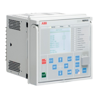
Section 3 1MAC054853-MB B 615 series overview A070704-ANSI V3 EN Figure 2: Example of the LHMI 3.2.1 Display The LHMI includes a graphical display that supports one character size. The character size depends on the selected language. The amount of characters and rows fitting the view depends on the character size. - Page 29 Section 3 1MAC054853-MB B 615 series overview A070705-ANSI V3 EN Figure 3: Display layout 1 Header 2 Icon 3 Content 4 Scroll bar (displayed when needed) • The header area at the top of the display view shows the current location in the menu structure.
-
Page 30: Leds
Section 3 1MAC054853-MB B 615 series overview 3.2.2 LEDs The LHMI includes three protection indicators above the display: Normal, Pickup and Trip. There are 11 matrix programmable LEDs on front of the LHMI. The LEDs can be configured with PCM600 and the operation mode can be selected with the LHMI, WHMI or PCM600. - Page 31 Section 3 1MAC054853-MB B 615 series overview A070680-ANSI V2 EN Figure 4: LHMI keypad with object control, navigation and command push buttons and RJ-45 communication port Close Escape Enter Clear Uplink LED Communication LED Communication port Open 10 Left 11 Down 12 Right 13 Key 14 Menu...
- Page 32 Section 3 1MAC054853-MB B 615 series overview Table 5: Object control push buttons Name Description Closing the object. Close The LED indicates the current object state. Opening the object. Open The LED indicates the current object state. Navigation The arrow buttons are used for navigation. To scroll information, press the arrow button several times or simply keep it pressed down.
-
Page 33: Local Hmi Functionality
Section 3 1MAC054853-MB B 615 series overview Commands Table 7: Command push buttons Name Description • Moving directly to main menu, if currently in any other menu. Menu • Moving between main menu, measurements and single-line diagram views. Changing the control position (remote or local) of the device. •... - Page 34 Section 3 1MAC054853-MB B 615 series overview Table 9: Pickup LED LED state Description Normal operation. A protection function has picked up and an indication message is displayed. • If several protection functions pick up within a short time, the last pickup is indicated on the display.
-
Page 35: Parameter Management
Section 3 1MAC054853-MB B 615 series overview 3.2.4.2 Parameter management The LHMI is used to access the relay parameters. Three types of parameters can be read and written. • Numerical values • String values • Enumerated values Numerical values are presented either in integer or in decimal format with minimum and maximum values. -
Page 36: Web Hmi
Section 3 1MAC054853-MB B 615 series overview A070816 V2 EN Figure 5: RJ-45 communication port and indication LEDs 1 Uplink LED 2 Communication LED When a computer is connected to the protection relay, the relay's DHCP server for the front interface assigns an IP address to the computer. The fixed IP address for the front port is 192.168.0.254. -
Page 37: Command Buttons
Section 3 1MAC054853-MB B 615 series overview • Single-line diagram • Importing/Exporting parameters • Report summary The menu tree structure on the WHMI is almost identical to the one on the LHMI. A070754 V6 EN Figure 6: Example view of the WHMI The WHMI can be accessed locally and remotely. - Page 38 Section 3 1MAC054853-MB B 615 series overview Table 12: Command buttons Name Description Enabling parameter editing. Disabling parameter editing. Writing parameters to the protection relay. Refreshing parameter values. Printing out parameters. Committing changes to protection relay's nonvolatile flash memory. Rejecting changes. Showing context sensitive help messages.
-
Page 39: Authorization
Section 3 1MAC054853-MB B 615 series overview Authorization Four user categories have been predefined for the LHMI and the WHMI, each with different rights and default passwords. The default passwords in the protection relay delivered from the factory can be changed with Administrator user rights. -
Page 40: Communication
Section 3 1MAC054853-MB B 615 series overview Communication The protection relay supports a range of communication protocols including IEC 61850, ® IEC 61850-9-2 LE, Modbus and DNP3. Operational information and controls are available through these protocols. However, some communication functionality, for example, horizontal communication between the protection relays, is only enabled by the IEC 61850 communication protocol. -
Page 41: Self-Healing Ethernet Ring
Section 3 1MAC054853-MB B 615 series overview All communication connectors, except for the front port connector, are placed on integrated optional communication modules. The protection relay can be connected to Ethernet-based communication systems via the RJ-45 connector (100Base-TX) or the fiber optic LC connector (100Base-FX). -
Page 42: Ethernet Redundancy
Section 3 1MAC054853-MB B 615 series overview 3.5.2 Ethernet redundancy IEC 61850 specifies a network redundancy scheme that improves the system availability for substation communication. It is based on two complementary protocols defined in the IEC 62439-3:2012 standard: parallel redundancy protocol PRP and high-availability seamless redundancy HSR protocol. - Page 43 Section 3 1MAC054853-MB B 615 series overview COM600 SCADA Ethernet switch Ethernet switch IEC 61850 PRP GUID-334D26B1-C3BD-47B6-BD9D-2301190A5E9D V3 EN Figure 8: PRP solution In case a laptop or a PC workstation is connected as a non-PRP node to one of the PRP networks, LAN A or LAN B, it is recommended to use a redundancy box device or an Ethernet switch with similar functionality between the PRP network and SAN to remove additional PRP information from the Ethernet frames.
-
Page 44: Pcm600 Tool
Section 3 1MAC054853-MB B 615 series overview GUID-207430A7-3AEC-42B2-BC4D-3083B3225990 V3 EN Figure 9: HSR solution PCM600 tool Protection and Control IED Manager PCM600 offers all the necessary functionality to work throughout all stages of the protection relay life cycle. • Planning •... -
Page 45: Connectivity Packages
REG615 Connectivity Package Ver.5.1 or later • REM615 Connectivity Package Ver.5.1 or later • RET615 Connectivity Package Ver.5.1 or later Download connectivity packages from the ABB Web site http://www.abb.com/substationautomation or directly with Update Manager in PCM600. 615 series ANSI Operation Manual... -
Page 47: Section 4 Using The Hmi
Section 4 1MAC054853-MB B Using the HMI Section 4 Using the HMI Using the local HMI To use the LHMI, logging in and authorization are required. Password authorization is disabled by default and can be enabled via the LHMI. To enable password authorization, select Main menu/Configuration/ Authorization/Passwords. - Page 48 Section 4 1MAC054853-MB B Using the HMI A070890 V2 EN Figure 11: Entering password Press to confirm the login. • To cancel the procedure, press A070889 V2 EN Figure 12: Error message indicating wrong password The current user level is shown on the display's upper right corner in the icon area.
-
Page 49: Logging Out
Section 4 1MAC054853-MB B Using the HMI 4.1.2 Logging out An automatic logout occurs 30 seconds after the backlight timeout. Press To confirm logout, select Yes and press A070837 V3 EN Figure 13: Logging out • To cancel logout, press 4.1.3 Turning the display backlight on The display backlight is normally off. -
Page 50: Selecting Local Or Remote Use
Section 4 1MAC054853-MB B Using the HMI 4.1.4 Selecting local or remote use The control position of the protection relay can be changed with the R/L button. In local position primary equipment, such as circuit breakers or disconnectors, can be controlled via the LHMI. -
Page 51: Adjusting The Display Contrast
Section 4 1MAC054853-MB B Using the HMI A071158-ANSI V2 EN Figure 14: Selecting a submenu Enter the submenu with Browse the information with A071160-ANSI V2 EN Figure 15: Protection relay information 4.1.6 Adjusting the display contrast Adjust the display contrast anywhere in the menu structure to obtain optimal readability. •... -
Page 52: Changing The Local Hmi Language
Section 4 1MAC054853-MB B Using the HMI 4.1.7 Changing the local HMI language Select Main menu/Language and press Change the language using Press to confirm the selection. Commit the changes. A071010 V2 EN Figure 16: Changing the LHMI language To change the language using a shortcut, press simultaneously anywhere in the menu. -
Page 53: Navigating In The Menu
Section 4 1MAC054853-MB B Using the HMI 4.1.9 Navigating in the menu Navigate the menus and change the display views on the screen with the keypad. • To navigate between main menu, measurements and single-line diagram, press • To move up or down in a menu, press •... -
Page 54: Changing The Default View
Section 4 1MAC054853-MB B Using the HMI A070860-ANSI V2 EN Figure 17: Scroll bar on the right • To scroll the view upwards, press • To scroll the view downwards, press • To jump from the last row to the first row, press again. - Page 55 Section 4 1MAC054853-MB B Using the HMI GUID-BA9EE384-E2F7-4390-9F7B-01E764703820-ANSI V1 EN Figure 18: Single-line diagram with one breaker and IEC symbols GUID-DC9A8A5E-3EBF-4C03-A3BC-CAD34B85269E-ANSI V1 EN Figure 19: Single-line diagram with one breaker and ANSI symbols Select the single-line diagram for the default view in Main menu/ Configuration/HMI/Default view.
-
Page 56: Changing Single-Line Diagram Symbol Formats
Section 4 1MAC054853-MB B Using the HMI 4.1.10.1 Changing single-line diagram symbol formats Select Main menu/Configuration/HMI/SLD symbol format and press Change symbol format with Press to confirm the selection. GUID-7350C17D-3F8A-476E-BF3D-EBDB690BF941-ANSI V1 EN Figure 20: Selecting ANSI as single-line diagram symbol format 4.1.11 Browsing setting values Select Main menu/Settings/Settings and press... -
Page 57: Editing Values
Section 4 1MAC054853-MB B Using the HMI A070858 V3 EN Figure 21: Selecting a setting group Press to confirm selection. To browse the settings, scroll the list with and to select a submenu press . To move back to the list, press A070859-ANSI V1 EN Figure 22: Example of submenus in the Settings menu... -
Page 58: Editing Numerical Values
Section 4 1MAC054853-MB B Using the HMI Changing the function block on or off affects to the visibility of its parameters in the menu. Setting function block off hides the function parameters. When changing function block on or off the parameters' visibility changes immediately. - Page 59 Section 4 1MAC054853-MB B Using the HMI For parameters with defined steps, digits smaller than the step value cannot be edited. Press to move the cursor to another digit. To select the minimum or maximum value, select the arrow symbol in front of the value.
-
Page 60: Editing String Values
Section 4 1MAC054853-MB B Using the HMI 4.1.12.2 Editing string values Activate the setting mode and select a setting. When editing string values, the cursor moves to the first character. Press to change the value of an active character. One press changes the value by one step. Press to move the cursor to another character. -
Page 61: Clearing And Acknowledging
Section 4 1MAC054853-MB B Using the HMI A070891 V3 EN Figure 26: Confirming settings • To exit without saving changes, select No and press • If the parameter has an edit-copy, the original parameter value is restored. • If the parameter does not have an edit-copy, the edited parameter value remains visible until the protection relay is rebooted. -
Page 62: Using The Local Hmi Help
Section 4 1MAC054853-MB B Using the HMI A070860-ANSI V2 EN Figure 27: Clear view Select the item to be cleared with Press , change the value with and press again. The item is now cleared. Repeat steps 2 and 3 to clear other items. Use the button as a shortcut for clearing. -
Page 63: Logging In
Section 4 1MAC054853-MB B Using the HMI To enable the WHMI, select Main menu/Configuration/HMI/Web HMI mode via the LHMI. Reboot the relay for the change to take effect. Log in with the proper user rights to use the WHMI. To establish a remote WHMI connection to the protection relay, contact the network administrator to check the company rules for IP and remote connections. -
Page 64: Identifying Device
Section 4 1MAC054853-MB B Using the HMI 4.2.3 Identifying device The Information menu includes detailed information about the device, for example, revision and serial number. Click the Information menu in the left navigation bar. Click a submenu to see the data. A070925-ANSI V2 EN Figure 29: Device information... -
Page 65: Menu Structure
Section 4 1MAC054853-MB B Using the HMI • The DFR records view shows the list of disturbance records. • The Fault records view shows the list of fault records. • The Single Line Diagram view shows the single-line diagram. • The Report summary page allows to save events, fault records, disturbance records, the load profile record and the parameter list. -
Page 66: Selecting Single-Line Diagram
Section 4 1MAC054853-MB B Using the HMI • Tests • Information • Clear • Language • Load profile record • Parameter list • WHMI settings 4.2.5 Selecting single-line diagram • Select Control/SLD in the left navigation bar or click Single Line Diagram in the menu bar to view the single-line diagram. -
Page 67: Showing Parameters
Section 4 1MAC054853-MB B Using the HMI GUID-C78B4218-3979-41ED-8B4E-83EACC433182-ANSI V1 EN Figure 32: Viewing the single-line diagram with ANSI symbols 4.2.6 Showing parameters Some function blocks have a function-specific On/Off setting. When the function setting is “Off”, all settings are hidden and when the function setting is “On”, all settings are visible based on the other visibility and hiding rules. - Page 68 Section 4 1MAC054853-MB B Using the HMI GUID-E32C7A87-CFC5-4BE5-86BC-0FB4CAFE75E2 V1 EN Figure 33: Function block On 615 series ANSI Operation Manual...
- Page 69 Section 4 1MAC054853-MB B Using the HMI GUID-F78F98AA-5055-4C05-926D-0A5CD3078CE8 V1 EN Figure 34: Function block Off The Parameter list page offers filtering functionality where only chosen parameters are displayed, saved or printed. There are various options for filtering. • Enabled settings hides settings of disabled function blocks. •...
-
Page 70: Editing Values
Section 4 1MAC054853-MB B Using the HMI GUID-6544E333-FED5-426C-999A-E3D375FF3E8B V1 EN Figure 35: Parameter list filter Click Parameter list in the left navigation bar. A071008-ANSI V2 EN Figure 36: Displaying parameters Select text (.txt) or comma separated values (.csv) file format and click Save to save the settings. - Page 71 Section 4 1MAC054853-MB B Using the HMI Some parameters, for example the Web HMI mode, cannot be set via the WHMI. A070929-ANSI V2 EN Figure 37: Enable writing to edit a value The selected setting group is shown in the Setting Group drop-down list. The active setting group is indicated with an asterisk *.
- Page 72 Section 4 1MAC054853-MB B Using the HMI A070930-ANSI V2 EN Figure 38: Editing a value • If the entered value is within the accepted value range, the selection is highlighted in green. If the value is out of range, the row is highlighted in red and a warning dialog box is displayed.
-
Page 73: Committing Settings
Section 4 1MAC054853-MB B Using the HMI GUID-E10EE091-CFB9-4278-9FA4-7340C26F5814-ANSI V1 EN Figure 40: Warning indicating that the values were not written to the protection relay If writing is enabled accidentally, click Disable Write. Disable Write cannot be selected when a value has already been written to the protection relay. - Page 74 Section 4 1MAC054853-MB B Using the HMI A070931-ANSI V2 EN Figure 41: Writing values to protection relay The values are not stored to the flash memory. Click Commit to write the values to the flash memory. • Click Reject to cancel saving settings. •...
-
Page 75: Clearing And Acknowledging
Section 4 1MAC054853-MB B Using the HMI A070932-ANSI V2 EN Figure 42: Committing changes Committing values takes a few seconds. If the values are not committed, they are not taken into use and they are lost after a reboot. 4.2.9 Clearing and acknowledging All messages and indications, including LEDs and latched outputs as well as registers and recordings, can be reset, acknowledged or cleared using the Clear menu. - Page 76 Section 4 1MAC054853-MB B Using the HMI A070935-ANSI V2 EN Figure 43: Selecting clear menu In the New Value list, select Clear to choose the item to be cleared. Click Write to IED. 615 series ANSI Operation Manual...
-
Page 77: Selecting Programmable Leds View
Section 4 1MAC054853-MB B Using the HMI A070936-ANSI V2 EN Figure 44: Clearing indications and LEDs 4.2.10 Selecting programmable LEDs view The programmable LEDs view shows the status of the programmable LEDs. These are the same LEDs that are located on the upper right side of the LHMI panel. •... -
Page 78: Selecting Event View
Section 4 1MAC054853-MB B Using the HMI A070946-ANSI V2 EN Figure 45: Monitoring alarms 4.2.11 Selecting event view The event view contains a list of events produced by the application configuration. When the event page is opened, it displays up to 100 latest events at one time. The event list is updated automatically. - Page 79 Section 4 1MAC054853-MB B Using the HMI A070947-ANSI V2 EN Figure 46: Monitoring events Click Freeze to stop updating the event list. Select a page from the drop-down list to view older events or select View all to show all events on the same page. 615 series ANSI Operation Manual...
-
Page 80: Selecting Dfr Records View
Section 4 1MAC054853-MB B Using the HMI GUID-328EBE0A-26D4-4063-AA1F-051C302EBCE2-ANSI V1 EN Figure 47: Events view To save the events in TXT or CSV file formats, select the file format from the drop- down list and click Save. The CSV file can be opened with a spreadsheet program such as OpenOffice.org Calc or Microsoft Excel. -
Page 81: Uploading Dfr Records
Section 4 1MAC054853-MB B Using the HMI GUID-2B46A09D-730E-45D3-BE30-20546BB6F8AD-ANSI V1 EN Figure 48: Selecting DFR record view 4.2.12.1 Uploading DFR records Click DFR records on the menu bar. To save the DFR record files, click the icon in the Download Files column of the record. -
Page 82: Triggering Dfr Recorder Manually
Section 4 1MAC054853-MB B Using the HMI 4.2.12.2 Triggering DFR recorder manually Click DFR records on the menu bar. Click Manual trigger. GUID-4F5661CB-2317-4F4C-9DA2-BFADFA71BA3E-ANSI V1 EN Figure 50: Manual triggering 4.2.12.3 Deleting DFR records Click DFR records on the menu bar. Delete records. -
Page 83: Selecting Phasor Diagrams
Section 4 1MAC054853-MB B Using the HMI GUID-E109C24F-8CC9-4074-A175-DA4820BA7913-ANSI V1 EN Figure 51: Deleting DFR records Click OK to confirm or Cancel to cancel the deletion. 4.2.13 Selecting phasor diagrams Install or enable the SVG plugin to view the phasor diagrams, if needed. Internet Explorer version 9.0 requires an SVG plugin to view the phasor diagrams whereas Internet Explorer versions 10.0 and 11.0 do not require any additional plugins for SVG support. - Page 84 Section 4 1MAC054853-MB B Using the HMI A070948-ANSI V3 EN Figure 52: Monitoring phasors Toggle the diagram visibility by selecting the diagram from the drop-down menu. 615 series ANSI Operation Manual...
- Page 85 Section 4 1MAC054853-MB B Using the HMI GUID-5F3C9CC8-1AE8-4235-836F-AC93E1E73708-ANSI V2 EN Figure 53: Toggling the diagram visibility Visible diagrams are indicated with an asterisk *. Change the size of the diagram by changing the zoom value. 615 series ANSI Operation Manual...
- Page 86 Section 4 1MAC054853-MB B Using the HMI GUID-690A11A9-FEC4-4558-A68F-16FBAC500E3B-ANSI V2 EN Figure 54: Zooming the diagram Click Freeze to stop updating the phasor diagram. No updates are displayed in the diagram. 615 series ANSI Operation Manual...
-
Page 87: Selecting Fault Records
Section 4 1MAC054853-MB B Using the HMI A071226-ANSI V3 EN Figure 55: The arrow extends outside the circle if the current value is too high 4.2.14 Selecting fault records Fom the main menu, select Monitoring/Recorded data/Fault record or click Fault records on the menu bar to view a list of all available fault records. Click a record from the Fault records list to open the fault record details view. - Page 88 Section 4 1MAC054853-MB B Using the HMI GUID-A6D3E116-CBAC-4F6B-8853-D97D32F73A71-ANSI V1 EN Figure 56: Fault records 615 series ANSI Operation Manual...
-
Page 89: Exporting Report Summary
Section 4 1MAC054853-MB B Using the HMI GUID-A49A6D73-2E18-48B3-9ECA-17908590688D-ANSI V1 EN Figure 57: Fault record parameters 4.2.15 Exporting report summary The Report summary page allows exporting events, fault records, disturbance records, the load profile record and the parameter list. Events, fault records and the parameter list are saved in TXT format. -
Page 90: Using Web Hmi Help
Section 4 1MAC054853-MB B Using the HMI GUID-9D3CAEA1-0456-4F46-BE58-69707EB6E94F V1 EN Figure 58: Report summary page 4.2.16 Using Web HMI help The context-sensitive WHMI help provides information on a single parameter, for example. • Move the mouse over the to display the help dialog box. 615 series ANSI Operation Manual... - Page 91 Section 4 1MAC054853-MB B Using the HMI A070927-ANSI V2 EN Figure 59: Opening the WHMI help 615 series ANSI Operation Manual...
-
Page 93: Section 5 Protection Relay Operation
Section 5 1MAC054853-MB B Protection relay operation Section 5 Protection relay operation Normal operation In a normal protection relay use situation, the basic operation includes monitoring and checking procedures. • Monitoring measured values • Checking object states • Checking function setting parameters •... -
Page 94: Dfr Recording Triggering
Section 5 1MAC054853-MB B Protection relay operation • Checking programmable LEDs • Reading event history • Checking fault records • Analyzing DFR recordings Document the disturbance before clearing the information from the protection relay. Only authorized and skilled personnel should analyze possible errors and decide on further actions. -
Page 95: Relay Self-Supervision
Section 5 1MAC054853-MB B Protection relay operation 5.2.4 Relay self-supervision The relay self-supervision handles internal run-time fault situations.The main indication of an internal fault is a flashing green Normal LED. Internal faults can be divided to hardware errors, run-time errors in the application or operating system and communication errors. -
Page 96: Settings For Different Operating Conditions
Section 5 1MAC054853-MB B Protection relay operation After completing the editing of setting group values, the new values are activated. The user can either commit the edited values or discard them. Setting values can also be copied from one setting group to another. 5.3.2 Settings for different operating conditions Protection relay settings can be designed for various operation conditions by defining... -
Page 97: Section 6 Operating Procedures
Section 6 1MAC054853-MB B Operating procedures Section 6 Operating procedures Monitoring 6.1.1 Indications The operation of the protection relay can be monitored via three different indications on the LHMI. • Three indicator LEDs with fixed functionality: Normal, Pickup and Trip •... -
Page 98: Monitoring An Internal Relay Fault
Section 6 1MAC054853-MB B Operating procedures A071264-ANSI V2 EN Figure 60: Indication message 6.1.1.2 Monitoring an internal relay fault The flashing green LED indicates an internal relay fault. Internal relay fault messages are shown in a dialog box. Only one dialog box can be shown at a time, therefore the relay has internal priority for indication messages and tripping data. -
Page 99: Monitoring Condition Monitoring Data
Section 6 1MAC054853-MB B Operating procedures Select Main menu/Monitoring/IED status/Self-supervision to monitor the latest fault indication. Press to scroll the view. 6.1.1.3 Monitoring condition monitoring data Select Main menu/Monitoring/I/O status/Condition monitoring. Press to scroll the view. Press to enter or to exit a submenu. - Page 100 Section 6 1MAC054853-MB B Operating procedures Indicator Description IC2-A Measured current amplitude phase C I1-A Measured positive sequence current I2-A Measured negative-sequence current I0-A Measured zero-sequence current I1B-A Measured positive-sequence current I2B-A Measured negative-sequence current I0B-A Measured zero-sequence current f-Hz Measured frequency Therm-Lev Thermal level of protected object...
-
Page 101: Using The Local Hmi For Monitoring
Section 6 1MAC054853-MB B Operating procedures Indicator Description QC-kVAr Reactive power, magnitude of instantaneous value, phase C PFA2 Power factor, magnitude of instantaneous value, phase A PFB2 Power factor, magnitude of instantaneous value, phase B PFC2 Power factor, magnitude of instantaneous value, phase C PA2-kW Active power, magnitude of instantaneous value, phase A PB2-kW... -
Page 102: Creating Digital Fault Records
Section 6 1MAC054853-MB B Operating procedures • DFR records • Fault records • Events • Load profile record 6.1.3.1 Creating digital fault records Normally DFR recordings are triggered by the protection relay applications but the recording can also be triggered manually. Select Main menu/DFR records. -
Page 103: Controlling And Uploading Of Dfr Recorder Data
Section 6 1MAC054853-MB B Operating procedures • Number of recordings currently in the protection relay's memory. • Remaining amount of recordings that fit into the available recording memory. • Recording memory used in percentage. • If the periodic triggering function is used, the time to trigger which indicates the remaining time to the next periodic triggering of the DFR. -
Page 104: Monitoring Events
Section 6 1MAC054853-MB B Operating procedures A071146-ANSI V2 EN Figure 64: Monitoring fault records 6.1.3.5 Monitoring events Event view contains a list of events produced by the application configuration. Each event takes one view area. The header area shows the currently viewed event index and the total amount of the events. -
Page 105: Monitoring And Uploading Load Profile Record
Section 6 1MAC054853-MB B Operating procedures A071148-ANSI V2 EN Figure 65: Monitoring events 6.1.3.6 Monitoring and uploading load profile record • Monitor the recording memory usage of the load profile via Main menu/ Monitoring/Load profile record. • Upload and analyze the load profile record with PCM600. 6.1.4 Remote monitoring The protection relay supports comprehensive remote monitoring. -
Page 106: Controlling
Section 6 1MAC054853-MB B Operating procedures Controlling 6.2.1 Controlling via the control menu The primary equipment can be controlled via the LHMI with the Open and Close buttons when the protection relay is set to the local-control mode and accessing the control operations is authorized. - Page 107 Section 6 1MAC054853-MB B Operating procedures A071170 V4 EN Figure 67: Opening a circuit breaker • To cancel the operation, select No and press A071172 V3 EN Figure 68: Cancelling operation The time between selecting the object and giving a control command is restricted by an adjustable time-out.
-
Page 108: Controlling With Single-Line Diagram
Section 6 1MAC054853-MB B Operating procedures 6.2.2 Controlling with single-line diagram In the single-line diagram view it is possible to open and close the controllable object. The position indication of the object can be seen on the single-line diagram. Select the object with if there are more than one controllable object in the single-line diagram. -
Page 109: Resetting Protection Relay
Section 6 1MAC054853-MB B Operating procedures Resetting protection relay 6.3.1 Clearing and acknowledging via the local HMI All messages and indications, including LEDs and latched outputs as well as registers and indications, including recordings can be reset, acknowledged or cleared with the Clear button. -
Page 110: Changing Protection Relay Functionality
Section 6 1MAC054853-MB B Operating procedures A070860-ANSI V2 EN Figure 71: Clear view Select the item to be cleared with Press , change the value with and press again. The item is now cleared. Repeat the steps to clear other items. Use the button as a shortcut for clearing. -
Page 111: Copying A Setting Group
Section 6 1MAC054853-MB B Operating procedures A071150 V3 EN Figure 72: Active setting group Select the setting group with Press to confirm the selection or to cancel. A071152 V3 EN Figure 73: Selecting the active setting group Commit the settings. Remember to document the changes you make. -
Page 112: Browsing And Editing Setting Group Values
Section 6 1MAC054853-MB B Operating procedures Select Main menu/Settings/Setting group/Copy group 1 and press Change the options with and press to confirm the selection. GUID-7C997215-CA0C-43E7-8D8B-324E69086C35 V1 EN Figure 74: Copying setting group 1 into 6 6.4.1.3 Browsing and editing setting group values Select Main menu/Settings/Settings and press Select the setting group to be viewed with and press... - Page 113 Section 6 1MAC054853-MB B Operating procedures To browse different function blocks, scroll the list with and to select a function block press . To move back to the list, press The function block list is shown in the content area of the display. On the left in the header, you see the current setting group, and on the right the menu path.
-
Page 114: Activating Programmable Leds
Section 6 1MAC054853-MB B Operating procedures A070922-ANSI V2 EN Figure 78: Editing the setting group value The active setting group is indicated with an asterisk * . Switching the Operation parameter of a function block on or off restarts all control and protection functions. 6.4.2 Activating programmable LEDs Select Main menu/Configuration/Programmable LEDs. - Page 115 Section 6 1MAC054853-MB B Operating procedures Select Main menu/Configuration/ HMI/Autoscroll delay and press Select delay time with Press to confirm the selection. GUID-799BFDDC-93D0-4887-818E-E7C7905F236D V1 EN Figure 79: Autoscroll delay 615 series ANSI Operation Manual...
-
Page 117: Section 7 Troubleshooting
Inspect the protection relay visually. • Inspect the protection relay visually to find any physical error causes. • If you can find some obvious physical damage, contact ABB for repair or replacement actions. Check whether the error is external or internal. •... -
Page 118: Checking Front Communication Link Operation
Section 7 1MAC054853-MB B Troubleshooting 7.1.3.1 Checking front communication link operation • To verify front communication, check that both LEDs above the RJ-45 communication port are lit. Table 17: Front communication LEDs Communication ok Uplink Steady green light Communication Flashing yellow light 7.1.3.2 Checking time synchronization •... - Page 119 The protection relay continues to perform internal tests during the fault situation. The internal fault code indicates the type of internal relay fault. When a fault appears, the code must be recorded so that it can be reported to ABB customer service. A071144-ANSI V1 EN Figure 80:...
- Page 120 Section 7 1MAC054853-MB B Troubleshooting Fault indication Fault code Additional information Internal Fault Faulty Signal Output relay(s) in card SO-relay(s),X130 located in slot X130. Internal Fault Faulty Power Output relay(s) in card PO-relay(s),X100 located in slot X100. Internal Fault Faulty Power Output relay(s) in card PO-relay(s),X110 located in slot X110.
-
Page 121: Warnings
LHMI. The warning indication message can be manually cleared. If a warning appears, record the name and code so that it can be provided to ABB customer service. A071222-ANSI V1 EN Figure 81:... - Page 122 Section 7 1MAC054853-MB B Troubleshooting Table 19: Warning indications and codes Warning indication Warning code Additional information Warning A watchdog reset has occurred. Watchdog reset Warning The auxiliary supply voltage has dropped Power down det. too low. Warning Error when building the IEC 61850 data IEC61850 error model.
-
Page 123: Correction Procedures
Section 7 1MAC054853-MB B Troubleshooting Warning indication Warning code Additional information Warning A continuous light has been detected on ARC3 cont. light the ARC light input 3. Warning Temporary error occurred in RTD card RTD card error,X130 located in slot X130. Warning Measurement error in RTD card located in RTD meas. -
Page 124: Setting Passwords
, change the password with and press again. Repeat steps 2 and 3 to set the rest of the passwords. If the administrator password is lost, contact ABB's technical customer support to retrieve the administrator level access. 7.3.4 Identifying relay application problems •... -
Page 125: Sample Data Interruptions
In case of permanent faults, the measurement chain should be checked to remove the origin of the faulty measurement data. In case of persistent faults originating from protection relay's internal faults, contact ABB for repair or replacement actions. 615 series ANSI Operation Manual... -
Page 127: Section 8 Commissioning
Section 8 1MAC054853-MB B Commissioning Section 8 Commissioning Commissioning checklist Familiarize yourself with the protection relay and its functionality before you start the commissioning work. • Ensure that you have all the needed station drawings such as single line and wiring diagrams. -
Page 128: Checking The Installation
Section 8 1MAC054853-MB B Commissioning Checking the installation 8.2.1 Checking power supply • Check that the auxiliary supply voltage remains within the permissible input voltage range under all operating conditions. • Check that the polarity is correct before powering the protection relay. 8.2.2 Checking CT circuits Check that the wiring is in strict accordance with the supplied connection... -
Page 129: Checking Vt Circuits
Section 8 1MAC054853-MB B Commissioning Both the primary and the secondary sides must be disconnected from the line and the protection relay when plotting the excitation characteristics. If the CT secondary circuit is opened or its ground connection is missing or removed without the CT primary being de-energized first, dangerous voltages may be produced. -
Page 130: Checking Binary Output Circuits
Section 8 1MAC054853-MB B Commissioning 8.2.4.2 Checking binary output circuits • Preferably, disconnect the binary output connector from the binary output cards. • Check all connected signals so that both load and voltage are in accordance with the protection relay specifications. 8.2.5 Checking optical connections Check that the Tx and Rx optical connections are correct. -
Page 131: Setting Protection Relay And Communication
Section 8 1MAC054853-MB B Commissioning Table 20: Predefined user categories and default passwords Username LHMI WHMI password User rights password VIEWER 0001 remote0001 Only allowed to view OPERATOR 0002 remote0002 Authorized to make operations ENGINEER 0003 remote0003 Allowed to change protection relay parameters, but no operation rights ADMINISTRATOR 0004... -
Page 132: Communication Link Options Between Pcm600 And Protection Relays
Section 8 1MAC054853-MB B Commissioning 8.4.1.1 Communication link options between PCM600 and protection relays Two options are available for the connection of PCM600 to the protection relay. • Direct point to point link between PCM600 and the protection relay • Indirect link via a station LAN or from remote via a network Point to point link The protection relay is provided with an RJ-45 connector on the LHMI. - Page 133 Section 8 1MAC054853-MB B Commissioning A071162 V1 EN Figure 82: Selecting TCP/IP protocol Select Obtain an IP address automatically and Obtain DNS server address automatically. 615 series ANSI Operation Manual...
- Page 134 Section 8 1MAC054853-MB B Commissioning A071224 V1 EN Figure 83: Obtaining IP address automatically Close all open windows by clicking OK and start PCM600. Administrator rights are requested to change the configuration as described above. Setting the rear communication To set up a standard PC with MicroSoft Windows operating system for rear communication: To open Network Connections, click Start, point to Settings, click Control Panel, and then double-click Network Connections.
- Page 135 Section 8 1MAC054853-MB B Commissioning A071162 V1 EN Figure 84: Selecting TCP/IP protocol Choose Use the following IP address. Enter an IP address and a subnet mask. Make sure that the IP address is unique, that is not used by any other device on the network. 615 series ANSI Operation Manual...
- Page 136 Section 8 1MAC054853-MB B Commissioning A071164 V1 EN Figure 85: Setting IP address and subnet mask Close all open windows by clicking OK and start PCM600. Administrator rights are requested to change the configuration as described above. Setting protection relay's IP address in PCM600 In PCM600 the protection relay's IP address can be defined via the first window of the wizard by including a new protection relay in the project or by entering the protection relay's IP address in the Object Properties window.
-
Page 137: Communication Settings
Section 8 1MAC054853-MB B Commissioning The used method depends on the time at which the IP address is available. Defining IP address in the Object Properties windows allows changing the IP address at any time. 8.4.2 Communication settings The protection relay is provided with an RJ-45 front port on the LHMI. This connector is mainly used for configuration and setting purposes. -
Page 138: Serial Communication Ports And Drivers
Section 8 1MAC054853-MB B Commissioning For more information, see the communication protocol manuals and the technical manual. 8.4.2.1 Serial communication ports and drivers Depending on the hardware configuration, the protection relay can be equipped with one or several UART-based serial communication ports. The communication ports can be either galvanic (RS-485, RS-232) or fiber optic. -
Page 139: Serial Link Diagnostics And Monitoring
Section 8 1MAC054853-MB B Commissioning COM parameter Values Hardware options Baudrate 1 = 300 All modes 2 = 600 3 = 1200 4 = 2400 5 = 4800 6 = 9600 7 = 19200 8 = 38400 9 = 57600 10 = 115200 [bits/sec] Serial mode parameter value must be “RS485 2wire”. - Page 140 Section 8 1MAC054853-MB B Commissioning Depending on the communication protocol, the serial driver software receives single characters or complete protocol frames, based on the frame start/stop characters or on timing. Monitoring data for a COM channel can be divided into basic and detailed diagnostic counters.
- Page 141 Section 8 1MAC054853-MB B Commissioning Table 23: Basic diagnostic counters Counter Function Characters received Counts all incoming non-erroneous characters. This counter operates regardless of if the serial driver is set to detect a whole protocol link frame or just separate characters. Frames received Counts all protocol specific non-erroneous frames received.
-
Page 142: Defining Ethernet Port Settings
Section 8 1MAC054853-MB B Commissioning Table 25: Link status Parameter Function Link status Link status in write direction: By writing 1 to the parameter the diagnostic counters are reset to 0. Link status in monitoring direction: If the driver is in use by any communication protocol, the monitoring value shows 1. -
Page 143: Connecting Jumper Connectors
Section 8 1MAC054853-MB B Commissioning 8.4.2.6 Connecting jumper connectors See the technical manual for details on jumper connectors. 8.4.2.7 Communication checklist Check the physical connections. After the settings are changed, allow them to be stored in the non-volatile memory (S character on the icon area of the LHMI). Reboot the unit to allow the setting changes to take effect in DNP3. -
Page 144: Setting The Local Hmi
Section 8 1MAC054853-MB B Commissioning 8.4.3 Setting the local HMI 8.4.3.1 Changing the local HMI language Select Main menu/Language and press Change the language using Press to confirm the selection. Commit the changes. A071010 V2 EN Figure 86: Changing the LHMI language To change the language using a shortcut, press simultaneously anywhere in the menu. -
Page 145: Changing Display Symbols
Section 8 1MAC054853-MB B Commissioning 8.4.3.3 Changing display symbols Use the keypad to switch between the display symbols IEC 61850, IEC 60617 and ANSI. Select Main Menu/Configuration/HMI/FB naming convention and press Change the display symbols with Press to confirm the selection. The protection relay has to be rebooted if the WHMI display symbols are changed. - Page 146 Section 8 1MAC054853-MB B Commissioning The DST on/off date must precede the selected DST on/off day and be within the same week as the DST shift. Table 26: Possible date values for DST change on Sunday Day of the DST shift DST on/off date (dd) First Sunday of the month Second Sunday of the month...
-
Page 147: Setting Protection Relay Parameters
Section 8 1MAC054853-MB B Commissioning 8.4.4 Setting protection relay parameters 8.4.4.1 Defining setting groups Selecting a setting group for editing Select Main Menu/Settings/Edit setting group. Select the setting group to be edited with Press to confirm the selection. Edit the settings. A070858 V3 EN Figure 87: Selecting a setting group... - Page 148 Section 8 1MAC054853-MB B Commissioning A071166 V3 EN Figure 88: Selecting a setting group To browse the settings, scroll the list with and to select a setting press To browse different function blocks, scroll the list with and to select a function block press .
- Page 149 Section 8 1MAC054853-MB B Commissioning A071168-ANSI V2 EN Figure 90: Selecting the setting group value Only values within the selected setting group can be changed. Press to change the value and to confirm the selection. A070922-ANSI V2 EN Figure 91: Editing the setting group value The active setting group is indicated with an asterisk * .
-
Page 150: Relay Parametrization
Section 8 1MAC054853-MB B Commissioning A071150 V3 EN Figure 92: Active setting group Select the setting group with Press to confirm the selection or to cancel. A071152 V3 EN Figure 93: Selecting the active setting group Commit the settings. Remember to document the changes you make. 8.4.4.2 Relay parametrization Protection relay parameters are set via the LHMI, WHMI or PCM600. -
Page 151: Defining Dfr Channel Settings
Section 8 1MAC054853-MB B Commissioning Setting parameters need to be calculated according to the electrical network conditions and the electrical characteristics of the protected equipment. The protection relay's settings need to be verified before the protection relay is connected to a system. Document all changes to parameter settings. -
Page 152: Selecting The Test Mode
Section 8 1MAC054853-MB B Commissioning 8.5.1 Selecting the test mode The test mode can be activated using the LHMI. The green Normal LED is flashing to indicate that the test mode is activated.By default, the test mode can only be changed from the LHMI. -
Page 153: Testing Functions
Section 8 1MAC054853-MB B Commissioning Select Main menu/Tests/Binary outputs/X100 (PSM)/X100-PO1 and press Select the value with Press to confirm the selection. If the optional BIO-module (X110) is included in the protection relay, the menu path could also be Main menu/Tests/Binary Outputs/X110 (BIO)/<binary output>. -
Page 154: Selecting The Ied Blocked Or Ied Test And Blocked Mode
Section 8 1MAC054853-MB B Commissioning A071156-ANSI V2 EN Figure 95: Internal fault test Select the value with Press to confirm the selection. 8.5.5 Selecting the IED blocked or IED test and blocked mode The IED blocked mode and the IED test and blocked mode can be activated using the LHMI. -
Page 155: Abb Product Data Registration
Pickup and/or Normal LEDs remain flashing. ABB Product Data Registration The ABB Product Data Registration feature traces composition changes in the protection relay's SW or HW. Traceability allows better support and maintenance possibilities. After a composition change, an LCT indication is seen on the LHMI at the protection relay startup. - Page 156 Section 8 1MAC054853-MB B Commissioning A071266 V2 EN Figure 97: LCT indication The number of composition changes can be seen from the Composition changes parameter in Main Menu/Monitoring/IED status. 615 series ANSI Operation Manual...
-
Page 157: Section 9 Glossary
Section 9 1MAC054853-MB B Glossary Section 9 Glossary 100BASE-FX A physical medium defined in the IEEE 802.3 Ethernet standard for local area networks (LANs) that uses fiber optic cabling 100BASE-TX A physical medium defined in the IEEE 802.3 Ethernet standard for local area networks (LANs) that uses twisted- pair cabling category 5 or higher with RJ-45 connectors 615 series Series of numerical protection and control relays for... - Page 158 Section 9 1MAC054853-MB B Glossary Daylight-saving time EEPROM Electrically erasable programmable read-only memory Electromagnetic compatibility Ethernet A standard for connecting a family of frame-based computer networking technologies into a LAN Function block Firmware System software or hardware that has been written and stored in a device's memory that controls the device FPGA Field-programmable gate array...
- Page 159 Section 9 1MAC054853-MB B Glossary Life cycle traceability Light-emitting diode LHMI Local human-machine interface Media access control Modbus A serial communication protocol developed by the Modicon company in 1979. Originally used for communication in PLCs and RTU devices. Modbus ASCII Link mode using 7-bit ASCII characters Modbus RTU Link mode using 8-bit binary characters...
- Page 160 Section 9 1MAC054853-MB B Glossary Single-line diagram Simplified notation for representing a three-phase power system. Instead of representing each of three phases with a separate line or terminal, only one conductor is represented. Single-line diagram Signal Matrix tool in PCM600 SNTP Simple Network Time Protocol Connector type for glass fiber cable...
- Page 164 — ABB Distribution Solutions Distribution Automation P.O. Box 699 FI-65101 VAASA, Finland Phone +358 10 22 11 ABB Inc. 655 Century Point Lake Mary, FL 32746, USA Phone +1-800-222 1946 www.abb.com/mediumvoltage www.abb.com/relion www.abb.com/substationautomation © Copyright 2019 ABB. All rights reserved.
Need help?
Do you have a question about the Relion 615 Series and is the answer not in the manual?
Questions and answers