Table of Contents
Advertisement
Quick Links
Advertisement
Table of Contents

Related Manuals for Universal Space Pin Setter


Summary of Contents for Universal Space Pin Setter
- Page 1 IMPORTANT www.universal-space.com Operation Manual...
- Page 2 Pin Setter Manual WE ARE HERE TO ASSIST For parts and service Have Questions? Contact us! UNIS SERVICE CENTER Tel: 972-241-4263 Fax: 214-919-4918 Email: service@unisusasupportcenter.com 04/18/2018...
-
Page 3: Table Of Contents
Pin Setter Manual CONTENT IMPORTANT SAFETY INSTRUCTIONS ................ 3 1. SPECIFICATIONS ..................... 5 2. CONTENTS OF THE ACCESSORY KIT ..............6 3. PART NAME ......................7 4. SET UP & INSTALLATION ..................8 5. HOW TO PLAY ......................12 6. GAME OPTION ....................... 13 7. -
Page 4: Important Safety Instructions
Pin Setter Manual Thank you for purchasing Pin Setter. We hope you enjoy the product. This manual contains valuable information about how to operate and maintain your game machine properly and safely. It is intended for the owner and/or personnel in charge of product operation. - Page 5 Pin Setter Manual Use the following safety guidelines to help ensure your own personal safety and to help protect your equipment and surrounding environment from potential damage. This product is an indoor game machine. Do not install outdoors. Avoid installing in the following places to prevent fire, electric shock, injury and/or machine malfunctioning: ...
-
Page 6: Specifications
Pin Setter Manual 1. SPECIFICATIONS Rated power supply: AC110V 50/60Hz; Min. Power consumption: 390W Max. Power consumption: 470W Dimension: W80.53×D34.17×H110.08 in W2045×D868×H2796 mm Weight:Approximately 1212.5 lb 550kg Part No: P139 Model No: C-522 NOTICE: After turning off the game, please wait at least 1 minute before restarting again. -
Page 7: Contents Of The Accessory Kit
Pin Setter Manual 2. CONTENTS OF THE ACCESSORY KIT Open the package and make sure all the items are included: 1. Following accessories Part No. Name Picture 1 P139-801-000 2 P139-802-000 3 P139-803-000 Fuse 4 P139-804-000 Power cord 5 P139-805-000... -
Page 8: Part Name
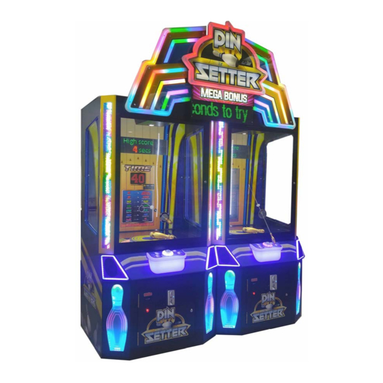
Pin Setter Manual 3. PART NAME Key Components Marquee Assy. MEGA BONUS Display Ring assy. 27" Monitor Rod assy. Rod handle Bowling pin Start button Ticket dispenser Assy. Coin mech. 04/18/2018... -
Page 9: Set Up & Installation
Pin Setter Manual 4. SET UP & INSTALLATION NOTICE We do not recommend using power tools as they may cause damage. This product is an indoor game machine. Do not install outdoors. Refer to IMPORTANT SAFETY INSTRUCTIONS (Pg. 3) for places to avoid ... - Page 10 Pin Setter Manual 4.3 Play Zone This machine requires space for playing and for maintenance as shown below. Leave space around the game upon installation: Service area: 20 in Service area Play area NOTICE Your unit must be leveled to operate properly.
- Page 11 Pin Setter Manual 4.4 Marquee Installation (This process requires assistance.) Before processing with assembly assure you have the following tools. Name Picture Phillips screwdriver Ladder Step 1 Stand on the ladder and place the marquee bracket on the top of the cabinet and fix it with four screws as picture shown.
- Page 12 Pin Setter Manual Step 4 Place the L&R stripe assy. on the bracket and fix it with six screws as picture shown. Please connect the plugs. 3 screws for one side 04/18/2018...
-
Page 13: How To Play
Pin Setter Manual 5. HOW TO PLAY 5.1 Insert coins. 5.2 Press the start button to begin 5.3 Use the Rod make the Pin stand up within game time. Less time you spend, more tickets you will get. Ring assy. -
Page 14: Game Option
Pin Setter Manual 6. GAME OPTION 6.1 Adjustment button instruction Open the coin door and there is a meter panel. Press Settings button to enter into the setting menu. Settings Test Reset 6.2 Setting menu 6.2.2 Basic Setting 6.2.1 Main menu... - Page 15 Pin Setter Manual 6.2.4Input Test 6.2.5 Output Test Ticket driver OFF/ON Insert coin Card reader inhibit OFF/ON Front window Card reader enable OFF/ON Go button Two side light bar OFF/ON Rod laying down Go button light OFF/ON Rod pulling up...
- Page 16 Pin Setter Manual 6.2.10 Daily Record Date Weekday RunTime Coins Tickets Payout 2014-06-061 Fri 00:01 0.00 Prev. Page Next Page Clear Back 6.2.11 Calibrate the detecting area Pin is set: No Detecting time:1.5 Operation tips Calibration: Reset button Back: Settings button...
-
Page 17: Trouble Shootings
Pin Setter Manual 7. TROUBLESHOOTING 7.1 Common Problem Please confirm that all connectors fit tightly. Symptom Possible Cause Recommended action Frame assembly connector is Game will not Check connector. loose. start Frame assembly fault Contact with UNIS Service. Turn on power SW again. If appeared... - Page 18 Pin Setter Manual If you see following error signs showing on the display, please try the recommended action. Display Possible Cause Recommended action Check and reconnect the The connection part of the loose ports of the PC or IO IO board and PC are loose.
- Page 19 Pin Setter Manual 7.2 System Recovery Operation (NOTE: Do not disconnect power during this process.) 1. Turn off the game. Remove recovery USB from the machine. (Note: This process may take up to 60 minutes) Insert the memory stick into the USB port at the back of the computer.
-
Page 20: Maintenance & Inspection
Pin Setter Manual 8. MAINTENANCE & INSPECTION 8.1 Safety Check Check the points listed before operating the machine. These checks are necessary for safe machine operation: 1. Test game before operation each day. 2. Conduct monthly routine checks of game components to ensure good working condition 3. - Page 21 Pin Setter Manual 8.3.1 Changing the pushing rod nylon wiring. Before processing with assembly assure you have the following tool and part. Name Picture Phillips screwdriver Nylon wiring Step 1 Tie a knot on one side of the Nylon wiring and guide it through two holes of the pushing rods as red arrow indicated.
- Page 22 Pin Setter Manual 8.3.2 Changing the turntable assy. Before processing with assembly assure you have the following tool and part. Name Picture Wrench Turntable assy. Step 1 Power off the game. Unplug this plug and loosen four screws in red area. Then, take out the whole turntable assy.
- Page 23 Pin Setter Manual 8.3.3 Changing the Bowling pin bottom assy. Before processing with assembly assure you have the following tools and part. Name Picture Phillips screwdriver L type wrench Circlip pliers Bowling pin bottom assy.(normal) Alternative Bowling pin bottom assy.(heavy) Step 1 Power off the game.
- Page 24 Pin Setter Manual Step 3 Use the pliers to remove the circlip. Then, follow the direction of yellow arrow, slightly push the red area part and remove it. Circlip Step 4 Install the Bowling pin bottom assy. Make sure it will be installed in place and fix with the washer.
- Page 25 Pin Setter Manual 8.3.4 Making the Bowling pin bottom assy. If you already get this part and the problem happens again, please replace the string. Name Picture Rope Step 1 Disassemble the Bowling pin Step 2 Use the new string to bunch the bottom assy.
- Page 26 Pin Setter Manual 8.3.5 Changing the rod assy. If the rod broke, please replace it. Before processing with assembly assure you have the following tool and part. Name Picture L type wrench Step 1 Use the wrench to loosen two screws...
- Page 27 Pin Setter Manual 8.3.6 Changing the ring assy. Name Picture Ring assy. (normal) Ring Loosen the spring ring as arrow indicated, and change into the new ring. 04/18/2018...
-
Page 28: Overall Construction
Pin Setter Manual 9. OVERALL CONSTRUCTION 9.1 General Assembly Part No. Code No. Name 1 P139-117-000 20221701A011 L&R side banding 2 P139-107-000 20621701A002 L speaker plastic 3 P139-138-000 20621701A030 L&R side window 4 P139-006-000 29921701A011 L marquee assy. 5 P139-142-000 20221701A045 Marquee mounting bracket 1... - Page 29 Pin Setter Manual Part No. Code No. Name 1 P139-143-000 20221701A042 Wiring cover plate 2 P139-140-000 20221701A021 Connecting plate 3 P139-010-000 29921701A015 String rolling assy. 4 P139-127-000 20221701A039 Display mounting plate 5 P139-198-000 26000042000A Wiring box 6 P139-128-000 20221701A017 Display tube mounting plate 2...
- Page 30 Pin Setter Manual Part No. Code No. Name 1 P139-200-000 26000051000 Ticket cover 2 P139-203-000 26000065000 Out of ticket light cover 3 P139-119-000 20221701A012 Ticket cover plate 4 P139-120-000 20221701A013 DBV front plate 5 P139-121-000 20221701A014 DBV back plate 6 P139-194-000 26000006000...
- Page 31 Pin Setter Manual Part No. Code No. Name 1 P139-123-000 20221701A015 R post 2 P139-124-000 20221701A016 R post back plate P139-101-000 20221701A001 L sensor pressing plate 2 P139-102-000 20621701A022 Sensor EVA 4 P139-008-000 29921701A008 Pushing rod assy. 5 P139-009-000 29921701A003 Turntable assy.
- Page 32 Pin Setter Manual 9.2 Rod assy. (without handle and ring) Part No. Code No. Name 1 P139-464-000 41108000005 2 P139-136-000 20221701A036 Rod baffle 3 P139-135-000 20621701A018 Fishing plate P139-137-000 20221701A037 Rod baffle P139-466-000 25108070004 Iron wire 0.1*2 5 P139-465-000 41108000001 Small ring 9.3 String rolling assy.
- Page 33 Pin Setter Manual 9.4 Turntable Assy. Part No. Code No. Name 1 P139-455-000 23404000120 Motor 2 P139-146-000 20221701A043 Turntable motor bracket 3 P139-147-000 20221701A024 Turntable shaft 4 P139-009-000 29921701A003 Turntable assy. 5 P139-148-000 29921701A005 Bowling pin bottom assy.(normal) 2 6 P139-151-000 20621701A021...
- Page 34 Pin Setter Manual 9. 5 Pushing rod Assy. Part No. Code No. Name 1 P139-457-000 22604000010 Micro SW 2 P139-455-000 23404000120 Motor 3 P139-156-000 20221701A025 Motor mounting bracket 2 4 P139-159-000 20621701A032 Damping plastic 5 P139-157-000 20221701A026 R swing rod...
- Page 35 Pin Setter Manual 9.6 L Marquee assy. Part No. Code No. Name 1 P139-724-000 20521701A004 L side decal P139-174-000 20621701A009 L marquee plate B P139-175-000 20621701A010 L marquee plate C P139-176-000 20621701A011 L marquee plate A P139-173-000 20621701A008 L marquee plate A...
- Page 36 Pin Setter Manual 9.7 R Marquee assy. Part No. Code No. Name 1 P139-725-000 20521701A005 R side decal P139-181-000 20621701A012 R marquee plate A P139-182-000 20621701A013 R marquee plate B P139-183-000 20621701A014 R marquee plate C P139-184-000 20621701A015 R marquee plate D...
- Page 37 Pin Setter Manual 9.8 Marquee assy. Part No. Code No. Name 1 P139-721-000 20521701A001 Marquee plastic decal P139-161-000 20621701A004 White plastic A P139-162-000 20621701A005 White plastic B P139-163-000 20621701A006 White plastic C P139-164-000 20621701A007 White plastic D P139-538-000 20321701A035 Marquee back plate...
- Page 38 Pin Setter Manual 9.9 Mega bonus assy. Part No. Code No. Name 1 P139-727-000 20521701A007 Display decal 2 P139-726-000 20521701A006 Logo plastic decal 3 P139-185-000 20221701A033 Display mounting frame 1 4 P139-186-000 20221701A051 Display mounting plate 1 9.10 Front door Assy.
- Page 39 Pin Setter Manual 9.11 Decals Part No. Code No. Name 1 P139-723-000 20521701A003 Back plastic decal 2 P139-712-000 20521701007 Control panel bed plate decal 2 3 P139-724-000 20521701A004 L side decal 4 P139-713-000 20521701008A Control panel decal 5 P139-715-000 20521701011...
- Page 40 Pin Setter Manual Part No. Code No. Name 1 P139-719-000 20521701018 Meter label 2 P139-730-000 20521701A010 Component label 3 P139-703-000 25600000037 Voltage warning label (L) 4 4 P139-729-000 20521701A009 TUV 110V nameplate 5 P139-728-000 20521701A008 110V nameplate P139-708-000 25600000095 Service label(L)
- Page 41 Pin Setter Manual 9.12 Electrical components Part No. Code No. Name P139-416-000 22002013002 RGB light strip 2.5m P139-431-000 22002015005 5050 light strip 3.2m 2 P139-429-000 50801000010 Display tube P139-406-000 21201027001 27" display P139-419-000 23307010003 DVI-HDMI video cable 4 P139-432-000 22002019002 WS2812b light strip 1.16m*4...
- Page 42 Pin Setter Manual Part No. Code No. Name 1 P139-434-000 22301000002 Coin mech. 2 P139-408-000 23100000005 Ticket dispenser P139-412-000 22003000003 LED bulb (12V) P139-413-000 22201000028 12V socket 4 P139-401-000 23000000005 Meter P139-409-000 22402010002 Red button P139-410-000 22402030002 Green button P139-411-000 22402050001 Black button 6 P139-417-000 22002013007 LED light strip-yellow 3.2m...
- Page 43 Pin Setter Manual Part No. Code No. Name 1 P139-427-000 21602000001A Power supply Short circuit board 2 P139-407-000 29711605001 (Fuseboard01(V1.0) 3 P139-423-000 29790700002 Ticket converted board 2 P139-443-000 23309000276 Cable set P139-414-000 21107210027 Android board 5 P139-435-000 29721701001 6 P139-404-000 29741315004...
- Page 44 Pin Setter Manual AC110 Part No. Code No. Name 1 P139-403-000 22601000005 Rocket SW 2 P139-402-000 21902000006 Fuse socket 2 P139-803-000 21901000013 Fuse 3 P139-405-000 21412000001 Binding post 2 4 P139-457-000 22604000010 Micro SW P139-804-000 23301010042 Power cord 2 P139-426-000 23201000001A...
-
Page 45: Wiring Diagram
Pin Setter Manual 10. WIRING DIAGRAM XKX2-PX-01 04/18/2018... - Page 46 Pin Setter Manual XKX2-PX-01 04/18/2018...
- Page 47 Pin Setter Manual 04/18/2018...
Need help?
Do you have a question about the Pin Setter and is the answer not in the manual?
Questions and answers