Table of Contents
Advertisement
Quick Links
HPE G2 Series Metered, Switched, and
Metered & Switched Power Distribution
Unit
User Guide
Abstract
This document is for the person who installs and maintains HPE PDU products. Hewlett Packard
Enterprise assumes that this person is qualified in the installation of electrical equipment and
trained in recognizing hazards in products with high energy levels.
Part Number: 879285-003
Published: May 2019
Edition: 3
Advertisement
Table of Contents

Related Manuals for HP HPE G2 Series


Summary of Contents for HP HPE G2 Series
- Page 1 HPE G2 Series Metered, Switched, and Metered & Switched Power Distribution Unit User Guide Abstract This document is for the person who installs and maintains HPE PDU products. Hewlett Packard Enterprise assumes that this person is qualified in the installation of electrical equipment and trained in recognizing hazards in products with high energy levels.
- Page 2 © Copyright 2018, 2019 Hewlett Packard Enterprise Development LP Notices The information contained herein is subject to change without notice. The only warranties for Hewlett Packard Enterprise products and services are set forth in the express warranty statements accompanying such products and services.
-
Page 3: Table Of Contents
Contents Before you begin..................7 Overview..............................7 Important safety information........................ 7 Introduction....................9 Classification overview........................9 Features.............................. 9 Form factors............................10 Rack mounting options and maximum configurations............... 10 Metered PDUs—rack mounting options ................10 Metered 0U (vertical) PDUs—maximum configuration............11 Metered 1U PDU (true 0U)—maximum configuration............12 Switched PDUs—rack mounting options................ - Page 4 Network management module......................50 Using the reset button......................51 Connecting the PDU to a LAN......................51 Connecting the PDU to a computer serial port.................. 52 Setting up serial communication.....................53 Remote configuration................55 Dynamic Host Configuration Protocol (DHCP).................. 55 Web configuration..........................55 Supported web browsers......................55 Logging in to the web interface....................55 Access privileges........................
- Page 5 Connecting a temperature sensor....................113 Connecting a temperature and humidity sensor................113 Connecting a 3-temperature and 1-humidity sensor................113 Connecting a rope fluid leak sensor....................114 Connecting an Open door sensor....................116 Connecting the sensor hub......................124 Detecting environmental sensors....................124 Configuring environmental sensors....................125 Configuring door sensors........................
- Page 6 Appendix F: Systems Insight Manager Integration .................162 Discovering the PDU......................162 Systems Insight Manager Overview..................163 Configuring HPE SIM to Receive Traps................164 Configuring the PDU to Send Traps to SIM................164...
-
Page 7: Before You Begin
Before you begin Overview This document provides installation and configuration instructions for installing a Hewlett Packard Enterprise G2 Series Metered, Switched, and Metered & Switched Power Distribution Units into a data center rack. Read all instructions before operating the equipment and save this document for future reference. Important safety information See the complete regulatory compliance notices in Safety and Compliance Information for Server, Storage, Power, Networking, and Rack Products on the Hewlett Packard Enterprise website. - Page 8 WARNING: To reduce the risk of fire, electric shock, and damage to the equipment: • HIGH LEAKAGE CURRENT. To reduce the risk of electric shock due to high leakage currents, make sure that there is a reliable grounded (earthed) connection before connecting power distribution products to AC power.
-
Page 9: Introduction
Introduction Classification overview The Hewlett Packard Enterprise G2 Series Metered, Switched, and Metered & Switched Power Distribution Units are intelligent PDUs designed to distribute power to IT equipment installed in a rack. These PDUs are either single-phase (1Ph) or three-phase (3Ph) models with electrical metering and switching capabilities. Each PDU provides power distribution to IT loads through C13, C19, or NEMA 5-20R outlets. -
Page 10: Form Factors
• Dual-color OLED display—Provides local access to view configuration settings and automatically enters sleep mode to conserve energy. • Dual network access—Using a redundant power delivery configuration and separate network connections, provides facilities management and IT (or Tenant) power consumption information. •... -
Page 11: Metered 0U (Vertical) Pdus-Maximum Configuration
HPE P/N Form factor 0U (Vertical) 0U (between RETMA U position in rack rails) P9R61A 0U—Full-height P9R77A P9R78A P9R79A P9R80A P9R81A P9R82A 0U—Half-height high density P9R83A 0U—Full-height high density P9R84A 0U—Half-height high density P9R85A 0U—Full-height high density P9R86A 0U—Full-height P9R87A 0U—Full-height HPE high-density model mounts on its side with outlets facing the back of the rack. -
Page 12: Metered 1U Pdu (True 0U)-Maximum Configuration
HPE P/N Form factor P9R87A 0U—Full-height P9R85A 0U—Full-height high density HPE high-density model mounts on its side with outlets facing the back of the rack. Metered 1U PDU (true 0U)—maximum configuration Mounting configuration for a 1U PDU in an HPE 1075 mm rack depth between the RETMA rails. These are the maximum number of PDUs per side of rack. -
Page 13: Switched 1U Pdu (True 0U)-Maximum Configuration
HPE P/N Form factor P9S08A 0U—Half-height P9S09A 0U—Mid-height P9S12A 0U—Half-height P9S14A 0U—Full-height P9S17A 0U—Full-height Switched 1U PDU (true 0U)—maximum configuration Mounting configuration for a 1U PDU in an HPE 1075 mm rack depth between the RETMA rails. These are the maximum number of PDUs per side of rack. HPE P/N Form factor P9S07A... -
Page 14: Load Segment And Phase Distinction
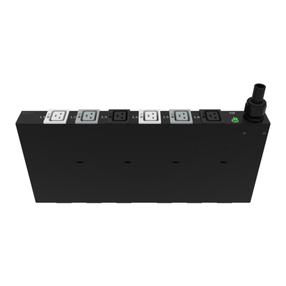
HPE P/N Form factor P9S20A 0U—Full-height P9S21A 0U—Full-height P9S22A 0U—Full-height P9S23A 0U—Full-height high-density P9S24A 0U—Full-height P9S25A 0U—Full-height high-density HPE high-density model mounts on its side with outlets facing the back of the rack. Load segment and phase distinction HPE G2 PDUs have colored receptacles to help distinguish between the different load segments and phases. All HPE 3Ph PDUs have different colored receptacles (white, light gray, and black) to distinguish the different phases. -
Page 15: Power Cord Retention
Power cord retention Integrated cord retention Each IEC C13 and C19 outlet on the PDU has an integrated cord retention feature that allows you to secure the cord to the outlet without needing a cord retention bracket. Procedure 1. Plug in the power cord. 2. - Page 16 3. Secure the tie wrap. Introduction...
-
Page 17: Locking Power Cord
Locking power cord Optional locking power cords can be used on each IEC C13 and C19 outlet on the PDU. Several lengths are available to support any configuration. The following illustration shows the locking power cord engaged with the outlets. NEMA 5-20R outlet retention bracket PDUs with 5-20R outlets require installation of a separate retention bracket to secure the equipment power cord at the outlet. - Page 18 Procedure 1. Using the screws provided, attach the bracket to one of the locations shown in the following illustrations, a - d. Introduction...
- Page 19 2. Install the PDU into the rack. 3. Feed the tie wrap through the hole in the retention bracket and around the input cord. Introduction...
- Page 20 Introduction...
-
Page 21: Installing The Pdu
Installing the PDU Required tools • Phillips screwdriver • Torx screwdriver Vertical PDU installation HPE Vertical PDUs include the following form factor models: • Half-height • Mid-height • Full-height Installing cord retention brackets The following instructions are for PDUs with NEMA 5-20R outlets, which require the installation of a separate retention bracket to secure the input power cord at the outlet. - Page 22 3. Insert the power cord. 4. Feed the tie wrap through the hole in the retention bracket and around the input cord. Installing the PDU...
- Page 23 Installing the PDU...
-
Page 24: Installing The Mounting Hardware
Installing the mounting hardware To assist with mounting in non-HPE racks, each vertical PDU has two mounting hole locations (M1 and M2) on the sides and back of the PDU for installing the buttons. When installing the mounting buttons, use either the M1 or M2 mounting holes as a set. - Page 25 • Outlets facing the back of the rack Installing the PDU...
- Page 26 • Outlets facing the front of the rack Installing the PDU...
-
Page 27: Vertical (0U) Pdu-Two Or More Installations
NOTE: These installation methods apply to all vertical models except for the high-density models. High- density units must be installed on its side with the outlets facing the back of the rack. For more information, see High-density PDU installation. Vertical (0U) PDU—two or more installations In order for two full-height (in a 42U/47U/48U rack), two mid-height (in a 36U/42U/47U/48U rack), or four half- height (in a 42U/47U/48U rack) vertical units to be mounted on one side of the rack, all units must be installed with the outlets facing towards the center of the rack. - Page 28 • Two mid-height PDUs with outlets facing towards the center of the rack. Installing the PDU...
- Page 29 • Four half-height PDUs with outlets facing towards the center of the rack. Installing the PDU...
-
Page 30: High-Density Pdu Installation
High-density PDU installation High-density PDUs have a unique form factor and are available in the following models: • Full-height Installing the PDU... - Page 31 • Half-height Installing the PDU...
-
Page 32: Pdu Shipping Retention For Rack Transportation
High-density PDUs must be installed on its side with the outlets facing the back of the rack. NOTE: Only one full-height PDU can be installed on each side of the rack, and only two half-height PDUs can be installed on each side of the rack. PDU shipping retention for rack transportation For vertical PDUs with attached input power cord (mid-height and full-height models) For rack transportation, mid-height and full-height vertical units with an attached input power cord must be... - Page 33 For Vertical PDUs with detached input power cord and for all half-height models For rack transportation, Vertical units with a detached input power cord and all half-height units must be secured using the shipping retention locking tape. Procedure 1. Remove the adhesive backing from only one side of the shipping retention locking tape. Installing the PDU...
- Page 34 2. Place the locking tape directly above the unit on the rack PDU mounting bracket. Installing the PDU...
- Page 35 Installing the PDU...
-
Page 36: Installing A Vertical Pdu In An Hpe Standard G1 Or 10K Series Rack
NOTE: If the PDU must be removed from the rack, remove the top piece of the locking tape and lift the unit out of the rack. Installing a vertical PDU in an HPE standard G1 or 10K series rack Installing a PDU in an older HPE 10K series rack requires option kit H6L32A, which is purchased separately. Procedure 1. - Page 37 2. Install the PDU in the rack frame. Installing the PDU...
-
Page 38: 1U Pdu Installation
1U PDU installation Installing cord retention brackets (PDUs with NEMA 5-20R outlets) PDUs with 5-20R outlets require installation of a retention bracket to secure the input power cord at the outlet. Procedure 1. Attach the retention bracket to the unit using the screws provided. Installing the PDU... -
Page 39: Mounting Options
2. Install the PDU into the rack. For more information, see Mounting hardware installation. 3. Insert the power cord. 4. Feed the tie wrap through the hole in the retention bracket and around the input cord. Mounting options The 1U PDU can be installed in any 1U location of the rack, or in the true 0U space between the RETMA rails, with the outlets facing down. -
Page 40: Mounting Hardware Installation
Mounting hardware installation Mounting the 1U PDU in a U position of the rack Procedure 1. Attach the mounting brackets to the unit using the screws provided. Installing the PDU... - Page 41 2. Install the cage nuts in the desired U location. 3. Screw the mounting bracket ears into the RETMA rail surface at the U location where the cage nuts were installed. Installing the PDU...
- Page 42 Mounting the 1U PDU in a U position between the RETMA rails Procedure 1. Attach the 0U mounting brackets to the unit using the screws provided. 2. Insert the mounting screws in the desired 0U location on the RETMA rails. Installing the PDU...
- Page 43 3. Rest the cutout on the end of the bracket on the screw and pivot the PDU until the holes line up with the hole in the bracket. Installing the PDU...
- Page 44 4. Insert and tighten the screws provided through the bracket into the holes in the RETMA rails of the rack. Installing the PDU...
-
Page 45: 2U Pdu Installation
2U PDU installation Installing cord retention brackets (PDUs with NEMA 5-20R outlets) Procedure Install the power cord retention bracket for 2U PDUs with 5-20R outlets. NOTE: No cord retention bracket is required for 2U PDUs with IEC C13 and C19 outlets. Installing the PDU... -
Page 46: Mounting Options
Mounting options This unit can be installed in any U location of the rack. Mounting hardware installation Procedure 1. Attach the mounting brackets to the unit. Each bracket requires four screws on each side. 2. Install the cage nuts at the desired U locations. Installing the PDU... - Page 47 3. Install the PDU. Installing the PDU...
-
Page 48: Grounding The Pdu
Grounding the PDU Connecting the ground bonding cable The PDU chassis has an external ground bonding point. The ground bonding screw is provided as an attachment point for conductors. Use a ground bonding cable if the rack contains any conductors for functional grounding or bonding of ungrounded metal parts. - Page 49 Installing the PDU...
-
Page 50: Connecting The Pdu
Connecting the PDU Connecting the PDU to a power source Always follow local and national codes when installing the PDU. The PDU must be connected to a dedicated circuit protected by a branch circuit breaker matching the PDU input plug type. NOTE: Make sure that the PDU power cord is long enough to reach the PDU power source. -
Page 51: Using The Reset Button
Using the reset button Press and hold the Reset button for 8 seconds to recover from a Network Management Module communication failure. NOTE: Pressing the Reset button only reboots the Network Management Module. It does not change the Energy (KWh) value and it does not affect the output voltage. Connecting the PDU to a LAN Connecting the PDU to a LAN provides communication through an Internet or intranet connection. -
Page 52: Connecting The Pdu To A Computer Serial Port
Connecting the PDU to a computer serial port If you cannot connect to a network, change the network setting using the serial interface. Connecting the PDU... -
Page 53: Setting Up Serial Communication
Procedure 1. Connect the PDU to a computer serial port, and then set the baud rate for a terminal program. 2. Use a CLI command to enable DHCP or set a static IP address. 3. Verify access to the web interface. The Ethernet LED on the PDU front panel indicates the communication status by color and display activity. - Page 54 • Parity: None • Stop bits: 1 • Flow control: None 5. Use the default initial login credentials. The user name and password are case sensitive. • User name: admin • Password: 12345678 (or your new password) The HPE> prompt appears after you have log in. 6.
-
Page 55: Remote Configuration
Remote configuration Dynamic Host Configuration Protocol (DHCP) The PDU is DHCP compatible. If the network does not use a DHCP server, see Connecting through a serial connection. When connected to the network, the PDU automatically obtains an IP address through DHCP. If necessary, log in to the web interface to configure the PDU and assign a static IP address. -
Page 56: Access Privileges
• If a user name and password were configured during the Network Configuration Setup, enter the user name and password in the appropriate fields. Press Login or Enter. • If a user name and password were not configured during the Network Configuration Setup, use the default user name, admin, and password, 12345678. - Page 57 displayed on setting and configuration dialog boxes. Before setting up users, determine the Roles that will be required. Each user must be assigned a Role, which defines the permissions granted to the user. Role Default permissions Full Full permissions that cannot be modified or deleted. Limited permissions that can be modified or deleted.
- Page 58 Adding a user role Procedure 1. On the User Settings page, click Add Role in the top right corner. 2. Enter a new role name and description, and set the administrator privileges, if required. 3. Click Save. The new role is displayed in the Roles list. Modifying users and roles Procedure 1.
- Page 59 • Server address • Port number • Port type • Base DN • User search DN • Login name attribute • User entry object class • Test name • Password 4. In the Bind DN field, enter the name of the account to be used to access the AD. For example: CN=myuser,CN=Users,DC=EMEA,DC=mydomain,DC=com 5.
- Page 60 Creating a certificate and private key Create sha1/sha256 and 1024bits/2048bits certificate and private key for the PDU.. Prerequisites The PDU needs the following environments to create a certificate and private key. • Operating system—Linux • Apps—OpenSSL Procedure Open Terminal on your Linux operating system. Enter mkdir cer.
- Page 61 11. Wait for the rebooting to complete. 12. Log in to the IP address of the PDU through https. You will see that the secure connection is established by the customized Certificate or you can check the connection on the SSH terminal by entering net cert, which will print the certificate information. 13.
-
Page 62: Web Menu Overview
Web menu overview Number Icon Description The search icon allows you to enter keywords and search for related results. The home icon provides an overview of the PDU with access to Dashboard, Alarms, Identification, and Control & Manage. The Alarm icon provides details of the active critical alarms and active warning alarms. - Page 63 Number Icon Description This icon allows you to set up Network Settings, System Management, SNMP Manager, Email Setup, Event Notifications, Trap Receiver, and Thresholds. This icon shows who is logged in (user or admin). You can change passwords and manage user accounts from this page. Remote configuration...
-
Page 64: Web Menu Options
Web menu options Menu Illustration Overview Alarms Remote configuration... - Page 65 Menu Illustration Help Table Continued Remote configuration...
- Page 66 Menu Illustration Language Remote configuration...
- Page 67 Menu Illustration Logs Remote configuration...
- Page 68 Menu Illustration Settings Remote configuration...
-
Page 69: Web Interface Overview
Web interface overview Summary page The dashboard summary page appears when you log in to the PDU web UI. This page displays the PDU total load percent (in a doughnut chart), PDU power energy, external sensor information, current, and voltage and load percent of each load segment. - Page 70 Control & Manage page Outlet grouping The Outlet Groups tab is under the PDU# tab on the Control and Manage page. Outlet Groups lists the outlet groups created, the power control options, and the "Add new outlet group" option. There are two types of outlet groups: •...
- Page 71 5. Add a group name and select the outlets you want to group. You can group a minimum of one outlet and a maximum of twelve outlets. 6. Click Save. The new outlet group appears in the Outlet Groups tab. Remote configuration...
- Page 72 Controlling an outlet group You can apply power controls to an outlet group. Procedure 1. Select the group name and the power control option from the Group Name and Power Control drop- down menu. 2. Click Apply. The group outlets are switched on or off accordingly. Remote configuration...
- Page 73 Editing an outlet group You can edit an outlet group name or add or remove outlets from an existing outlet group. Procedure 1. Select the outlet group you want to edit. 2. Click Edit. 3. Edit the outlet group name, delete an existing outlet, or select a new outlet. 4.
- Page 74 Deleting an outlet group Procedure 1. Select the outlet group you want to delete. 2. Click Delete. 3. Click Yes to confirm that you want to delete the outlet group. Identification page The Identification page displays system information such as the system name, contact name, email, phone, and location.
- Page 75 Alarms page The Alarms page displays the generated alarms. Alarms are categorized by severity level: • Active critical alarms • Active warning alarms The alarms icon displays the count of critical alarms and warning alarms. The count is reduced as the alarms are cleared.
- Page 76 View Logs page The event log lists the events, applications, and audit logs with the time stamp of when the event log was generated. All user activities are logged and displayed on the View Logs page. You can download an event log as an Excel sheet or clear an event log by using the Download or Clear button in the top right corner of the page.
- Page 77 Network Settings page The Network Settings page allows you to edit the IP Configuration, Web/REST API access configuration, SSH/FTP Configuration, Network Time Protocol, Date/Time Settings, and daylight-savings time. To access the Network Settings page, select Settings > Network Settings. You can also perform the following tasks on this page: •...
- Page 78 Prerequisites • • Procedure 1. Enter the PDU IP address in Google Chrome and login to the PDU using the credentials. 2. Navigate to the Network Settings page and enable RESTapi Access Configuration. 3. Click Save, and then confirm and apply changes. The PDU reboots.
- Page 79 ◦ Enter the valid primary and secondary NTP server addresses. ◦ Select the desired GMT offset time from the drop-down list. Daylight savings time Procedure 1. Enable daylight savings time for the PDU time by setting a 1 hour or 30 minute offset. 2.
- Page 80 Email Setup page Procedure 1. Navigate to Settings > Email Setup. 2. Edit the SMTP account settings 3. Add the email server address, sender address, and port number, and then set the number of retries allowed. 4. Enable authentication and set the user name and password, if required. When server authentication is disabled, user name and password might be empty.
- Page 81 PDU Thresholds page Procedure 1. Navigate to Settings > Thresholds. 2. Set the threshold values for PDU power, phase current, phase voltage, circuit breaker current, outlet power, and external sensors. PDU power thresholds Procedure 1. On the PDU Thresholds page, click the PDU Power Threshold edit pencil. 2.
- Page 82 4. Set the Reset Threshold value and Alarm State Change Delay value. 5. Click Save. Power Input phases Procedure 1. In the Input Phases tab of PDU Thresholds page, click the Edit pencil icon for the PDU input current and voltage phases.
- Page 83 Control Management When thresholds are enabled for alarms, the PDU generates the alarms in order of priority: 1. Power alarms 2. Circuit breaker 3. Input phase 4. External sensor 5. Outlet alarms The alarms are checked at 20-minute intervals. You can set individual thresholds for High Critical, High Warning, Low Warning, and Low Critical. To enable two or more thresholds, set the condition for the threshold values.
- Page 84 Remote configuration...
-
Page 85: Simple Network Management Protocol (Snmp)
Simple Network Management Protocol (SNMP) SNMP configuration IMPORTANT: For SNMP OID (Delta PDU) Pdu3InputPhaseCurrent 1.1, the value is calculated as Phase Current * sqrt 3 for both Master and Slave. The GUI threshold page displays as "PDU 1-displays Phase 1 current." Setting up SNMP Procedure 1. -
Page 86: Configuring Snmp V1/2C Manager
Configuring SNMP v1/2c Manager Procedure 1. On the SNMP Management page, click the edit pencil icon of the IP address to be configured. 2. Choose the access rights for the Read community and the Write community. 3. Click Enable. 4. Click Save. SNMP v3 Manager Simple Network Management Protocol (SNMP) -
Page 87: Trap Receiver
Trap Receiver Setting up an SNMP trap receiver Procedure 1. Navigate to Settings > SNMP Manager. 2. Select SNMP Port, and then set the trap port number. 3. Navigate to Settings > Trap Receiver. 4. Edit the SNMPV1 Trap Receiver by setting the name, host IP address, and community string. 5. - Page 88 • Select Password as Authentication Phrase or enter a new unique password to use for authentication, and then enter it again in the Confirm Authentication Pass Phrase field. • Select Authentication Pass Phrase as Privacy Pass Phrase to use the user's authentication passphrase as the privacy passphrase, or enter a new privacy passphrase in the Privacy Pass Phrase field, and then enter it again in the Confirm Privacy Pass Phrase field.
-
Page 89: Configuring Local Access
Configuring local access Connecting through a serial connection You can access the following PDU information through a serial connection by running CLI commands. • System configuration • Network Configuration • User Operation • Device Settings • Power Measurements • Switch Outlets On/Off. A serial connection also requires a terminal emulation program, such as HyperTerminal, or the use of an SSH client, such as PuTTY. -
Page 90: Logging In With The Cli
Command variables are represented in command input syntax surrounded by angle braces (< >). Optional parameters are represented in command input syntax surrounded by straight brackets ([ ]). For data of type array, the 'x' character as index of array in command input syntax means all indexes. You must be logged in to the PDU before commands can be sent. - Page 91 6. Enter your user name, and then press Enter. 7. Enter your password, and then press Enter. You are now logged in to the SSH. For CLI commands, see Appendix A: CLI commands. NOTE: An SSH connection is not available when serial connection is enabled. Configuring local access...
- Page 92 Configuring local access...
-
Page 93: Controlling Outlets Using Ssh
Controlling outlets using SSH Procedure 1. Log into the PDU web UI. 2. Navigate to Settings > Network Settings and enable SSH Configuration with the default port. 3. Open PuTTY configuration, and then enter the host name and port number. 4. -
Page 94: Local Display
Local display This section contains operation information for the Hewlett Packard Enterprise G2 Series Metered, Switched, and Metered & Switched Power Distribution Units. OLED display The OLED display provides information about the PDU and connected devices. The OLED window flashes red when a critical alarm is active. -
Page 95: Oled Menu Structure
LED state Description Green, red, orange Upgrading blinking In USB mode OLED menu structure Local display... -
Page 96: Main Menu Selections
Main menu selections The PDU menu selection hierarchy consists of Setup, Alarms, Power, and Sensors. On the main menu, scroll down to highlight Setup, and then press Select. Scroll down to select a submenu and press Select to display the submenu options. To return to the previous menu, press Menu. Setup menu The Setup menu provides user configuration options including Network, Device, Screen, Language, USB, and Units. - Page 97 Device submenu The Device submenu provides the SKU number, Serial number, MAC address, and Firmware version. On the Setup menu, scroll down to highlight the Device submenu. Press Select to display the options screen. To set the values for the selected option, press Select to display the screens. To return to the previous menu, press Menu.
- Page 98 Screen submenu The Screen submenu allows you to customize settings for Contrast, Rotate, and Always On. On the Setup menu, scroll down to highlight Screen. To display the screens to set the values for the submenu, press Select. After you select the values, press Select to set the values as displayed on the screen. To return to the previous menu, press Menu.
- Page 99 Local display...
- Page 100 Language submenu The Language submenu allows you to select the language. On the Setup menu, scroll down to highlight Lang. To display the screens to set the values for the submenu, press Select. After you select the values, to set the values as displayed on the screen, press Select.
- Page 101 Local display...
-
Page 102: Alarms Menu
Units submenu The Units submenu displays the temperature units. On the Setup menu, scroll down to highlight Units. To display the screens to set the values for the submenu, press Select. After you select the values, to set the values as displayed on the screen, press Select. To return to the previous menu, press Menu. Alarms menu The Alarms menu filters and displays active alarms for the PDU. -
Page 103: Power Menu
Select and scroll down to view active alarm data. When you finish your review, to return to the main menu, press Menu. If the backlight was blinking red to indicate an active alarm, the backlight returns to normal. Power menu The Power menu manages Device, Phase, Breaker, and Outlet functions. - Page 104 Phase submenu The Phase submenu displays information about the status of 3-phase power used by the system. On the Power menu, scroll down to highlight Phase and press Select to display the screens. After you select the values, press Select to set the values as displayed on the screen. To return to the previous menu, press Menu.
- Page 105 Breaker submenu The Breaker submenu displays the breaker quantities of 1Ph or 3Ph PDUs. On the Power menu, scroll down to highlight Breaker and press Select to display the screens. After you select the values, press Select to set the values as displayed on the screen. To return to the previous menu, press Menu. Figure 4: FOR 1Ph WITH BREAKERS Local display...
- Page 106 Figure 5: FOR 3Ph WITH 6 BREAKERS Outlet submenu The Outlet submenu displays the voltage, current, and power from outlet number 1 to number 10. On the Power menu, scroll down to highlight Outlet and press Select to display the screens to set the values for the submenu.
- Page 107 Local display...
-
Page 108: Sensors Menu
Sensors menu The Sensors menu displays information about the temperature, humidity, door switch, and fluid leak. On the main menu, scroll down to highlight Sensors and press Select. To select a submenu, scroll down and press Select to display the submenu options. To return to the previous menu, press Menu. NOTE: A maximum of six sensors can be configured per PDU. - Page 109 Setting up a daisy chain The following procedure describes how to connect up to four PDUs of the same SKU through a single IP address. Procedure 1. After the initial PDU is configured, connect an Ethernet cord from the RS485-2 port on the configured PDU to the Serial+RS485-1 port on the second PDU in the daisy chain line.
-
Page 110: Connecting And Configuring Optional Hardware
The optional environmental sensors can be installed before or after completing the PDU installation or startup, and can be installed without turning off power to the PDU or the devices connected. HPE G2 Series Metered, Connecting and configuring optional hardware... - Page 111 All HPE G2 Series Metered, Switched, and Metered & Switched Power Distribution Units have two physical sensor ports, and each PDU can collect a total of eight sensor measurements (or readings). For example, if a PDU has an Open/Close door sensor (P9T03A) and an Environmental 3-temperature + 1-humidity sensor (P9T02A) connected, both physical sensor ports are used with a total of five sensor measurements recorded.
-
Page 112: Temperature Sensor
Figure 7: Sensor Ports for Horizontal PDU Temperature sensor If a temperature sensor is added to the PDU, the sensor units operate in the following ways: • Temperature units can alternate between Fahrenheit or Celsius. A user can change the temperature units from either the OLED display or User Accounts screen. -
Page 113: Connecting A Temperature Sensor
Values Displayed Navigation Serial dev sensor [pduID] SNMp pdu3TemperatureScale pdu3TemperatureTable • Current temperature readings are displayed on the Summary page. • Connecting a temperature sensor Procedure 1. Secure the sensor to the perforated area on the rack enclosure door by threading the provided cable tie through the recessed channel in the sensor box and through the door. -
Page 114: Connecting A Rope Fluid Leak Sensor
4. Use the RJ45 quick disconnect coupler and an Ethernet cable to extend the length of the sensor input cable and/or to serve as an easy disconnect point for the rack door removal. 5. Plug the sensor cable (or the connected Ethernet cable) into the Sensor-1 or Sensor-2 port on the PDU. Connecting a rope fluid leak sensor Procedure 1. - Page 115 NOTE: If mounting to a cabinet or wall, use the provided adhesive-backed mount. Use of the adhesive- backed mount in the detection area (floor) may prevent or delay leakage notification. Connecting and configuring optional hardware...
-
Page 116: Connecting An Open Door Sensor
Connecting an Open door sensor Procedure 1. Assemble magnetic sensor to bracket. Adhere magnetic sensor to bracket using adhesive strip Connecting and configuring optional hardware... - Page 117 2. Mounting position of the rear door sensor is shown in the following illustration. Connecting and configuring optional hardware...
- Page 118 3. Mounting position of sensor bracket on the rear door is shown in the following illustration. Mount bracket with magnetic sensor to rear door at a distance around 58mm (2.28 in) from the center of the rack on the second row of perforated holes, using the flat-head screws provided. 4.
- Page 119 5. Adhere switch sensor to the inner frame of the rack while aligning it with the magnetic sensor mounted to the door. Connecting and configuring optional hardware...
- Page 120 Connecting and configuring optional hardware...
- Page 121 6. Adhere the switch sensor to rack frame using an adhesive strip. You can select the location, but it must be opposite the door hinge. Connecting and configuring optional hardware...
- Page 122 7. To mount the magnetic sensor to the front door, stick it to the inner door frame using the adhesive strip. Verify that it is aligned with the rack sensor. Connecting and configuring optional hardware...
- Page 123 8. The following illustrations shows the mounting position of sensors to the front door. Connecting and configuring optional hardware...
-
Page 124: Connecting The Sensor Hub
Connecting the sensor hub The sensor hub contains four parallel RJ45 ports, labeled 1 through 4, for connecting to the PDU and up to three sensors. Any of the RJ45 ports can be used to connect to the PDU or sensors. The numbered ports help when documenting which sensor is being used with the PDU. -
Page 125: Configuring Environmental Sensors
The sensor type, name, PDU ID, PDU name, and PDU location is displayed for each sensor. 3. Confirm that the serial number on the sensor device matches the number in the sensor table. Configuring environmental sensors To configure the sensor name, location, alarms, notifications, and details, open the web interface. Procedure 1. -
Page 126: Spares
Spares Ordering spares Procedure • To order a spare, visit the Hewlett Packard Enterprise website (http://www.hpe.com/info/hpparts). • To replace parts under warranty, contact a Hewlett Packard Enterprise authorized service representative. Metered PDU spare parts list Description Spare part number P9R45A HPE G2 Mtrd 1.9kVA/C20 1U NA/J PDU 870286-001 P9R46A... -
Page 127: Switched Pdu Spare Parts List
Description Spare part number P9R83A HPE G2 Mtrd 3P 17.3kVA/C13-C19 NA/J 870130-001 P9R84A HPE G2 Mtrd 3P 22kVA/60309 Vt INTL PDU 870132-001 P9R85A HPE G2 Mtrd 3P 22kVA/C13-C19 Vt INTL 870134-001 P9R86A HPE G2 Mtrd 3P 17.3kVA/12 C13 N/J PDU 870129-001 P9R87A HPE G2 Mtrd 3P 22kVA/ 24 C13 C19 N/J... -
Page 128: Spare Options
Spare options Description Spare part number PDU Horizontal Network Management 874564-001 Card Module PDU Vertical Network Management 874565-001 Card Module DB9 to RJ45 Cable 874724-001 Hardware options For information on the supported hardware options, see the Hewlett Packard Enterprise website (http:// www.hpe.com/info/rackandpower). -
Page 129: Websites
Websites General websites Hewlett Packard Enterprise Information Library www.hpe.com/info/EIL Single Point of Connectivity Knowledge (SPOCK) Storage compatibility matrix www.hpe.com/storage/spock Storage white papers and analyst reports www.hpe.com/storage/whitepapers For additional websites, see Support and other resources. Websites... -
Page 130: Support And Other Resources
Support and other resources Accessing Hewlett Packard Enterprise Support • For live assistance, go to the Contact Hewlett Packard Enterprise Worldwide website: http://www.hpe.com/assistance • To access documentation and support services, go to the Hewlett Packard Enterprise Support Center website: http://www.hpe.com/support/hpesc Information to collect •... -
Page 131: Customer Self Repair
Customer self repair Hewlett Packard Enterprise customer self repair (CSR) programs allow you to repair your product. If a CSR part needs to be replaced, it will be shipped directly to you so that you can install it at your convenience. Some parts do not qualify for CSR. -
Page 132: Documentation Feedback
www.hpe.com/support/Safety-Compliance-EnterpriseProducts Additional regulatory information Hewlett Packard Enterprise is committed to providing our customers with information about the chemical substances in our products as needed to comply with legal requirements such as REACH (Regulation EC No 1907/2006 of the European Parliament and the Council). A chemical information report for this product can be found at: www.hpe.com/info/reach For Hewlett Packard Enterprise product environmental and safety information and compliance data, including... -
Page 133: Appendix
Appendix Appendix A: CLI commands Help commands HPE>? Description List all available PDU CLI commands. Example output HPE>? PDU system configure and setting PDU net application configure and setting PDU user operation PDU device setting PDU power setting System commands sys date [year-month-day] Description Query or set system date. - Page 134 sys ntp <IP Address> Description Synchronize system date and time, with NTP server you set. Example output >sys ntp 69.25.96.13 NOTE: IP address must be a valid NTP server address. sys ver Description Query system version information, including firmware, bootloader, language, and web. Example output HPE>sys ver E000...
- Page 135 sys upd lan Description Update system firmware with existing PDU .bin file. Example output HPE>sys upd lan E801 system will enter upgrade mode after reboot System Reboot now, Are you sure? (Y/N):Y NOTE: There must be a valid file named HPE.bin, existing under directory/fw. NOTE: If in daisy-chain configuration, the master will also upgrade the firmware on all the slaves.
- Page 136 NOTE: If in daisy-chain configuration, the master will also upgrade the bootloader on all it's slaves. sys upd conf Description Update system configuration. Example output HPE>sys upd conf E801 system will enter upgrade mode after reboot System Reboot now, Are you sure? (Y/N):Y NOTE: There must be a valid file named conf.ini existing under directory/fw.
-
Page 137: Network Commands
Network commands net ssh [on/off] Description Query or on/off SSH. Example output HPE>net ssh E000, SSH Port: 22 SSH Server is running HPE>net ssh on E000 HPE>net ssh off E000 net FTPs [on/off] Description Query or on/off FTPs. Example output HPE>net FTPs E000, FTPSS Port: 21... -
Page 138: User Commands
Example output HPE>net mac E000 MAC Addr: C8-45-44-66-2B-26 net tcpip Description Query network IP information. Example output HPE>net tcpip E000 IPv4 Addr: 192.168.30.39 net tcpip <dhcp> Description Set network to DHCP mode. Example output HPE>net tcpip dhcp E801 Network is reconfigured, Please reboot to validate System Reboot now, Are you sure? (Y/N): Y net tcpip<static ip, mask, gateway>... -
Page 139: Device Commands
Example output HPE>user list E000 Role ------------- admin admin user user User unlock<username> Description Unlock specified user. Example output HPE>usr unlock user E000 HPE>usr unlock admin E000 NOTE: Account is locked temporarily if login failures exceed the maximum allowed number of failed logins. Use this command to unlock it. - Page 140 dev outlet <PDUID> status Description Query all outlet status with specified PDUID. Example HPE>Dev outlet 1 status E000 Relay outlet status Outlet#1: Close Outlet#2: Close Outlet#3: Close Close Outlet#4: CLose Outlet#5: Close Outlet#6: Close Outlet#7: Close Outlet#8: Close Outlet#9 Close Outlet#10: Close Outlet#11: Close Outlet#12: Close NOTE: This command is invalid for Metered PDUs.
-
Page 141: Power Commands
dev ver <slipaddr> Description Query sensor, power, or delay firmware version. Example output HPE>dev ver 1 HPE>dev ver 15 HPE>dev ver 35 NOTE: Relay: start from 1. Power: start from 15. Sensor: start from 35. Power commands pwr unit [idx] Description Query device information and query specified index unit electric information. -
Page 142: System Configure Commands
power factor: 0.00 energy: 0.000kWh pwr cb [idx] Description Query specified circuit breaker electric information. Example output HPE>pwr cb 1 E000 PDU CB 1 power Feature voltage: 0V current: 0.0A active power: 0W apparent power: 0W power factor: 0.00 energy: 0.000kWh outlet [idx] Description Query specified outlet electric information. - Page 143 sys date Description Set the PDU date. Example output HPE>sys date SUCCESS Date:2013-08-12 Time:04:58:16 sys time[hh:mm:ss] Description Set the user input time. Example output HPE>sys time 09:20:50 SUCCESS sys time Description Query PDU time. Example output HPE>sys time SUCCESS Date:2013-08-12 Time:09:20:53 sys ntp [primary_ip] [secondary_ip] Description...
- Page 144 Example output HPE>sys ver SUCCESS Firmware Version: 2.0.0.A Bootloader Version: 2.25 LANGUAGE Version 3.02 Web Version: 3.34 sys def Description Set the PDU system to default settings. Example output HPE>sys def SUCCESS Press reset button 8 seconds to finish PDU configuration recover Press any key to cancel...
-
Page 145: Network Application Configure Commands
sys upd boot Description Updates the boot file. sys upd all Description Updates all the files. Example HPE>sys upd all Reboot required for change to take effort System Reboot now, Are you sure?(Y/N): sys log [del/edit] [data/event] Description Edits or deletes the event and data file. Example HPE>sys log del event SUCCESS... - Page 146 Status: OFF HPE>net https on Reboot required for change to take effort WEB protocol is changed, Please reboot to validate System Reboot now, Are you sure?(Y/N): net redfish [on/off] Description Sets Redfish on/off. Example output HPE>net redfish SUCCESS Status: ON HPE>net redfish off SUCCESS Status: OFF...
-
Page 147: Appendix B: Firmware Update Procedure
Reboot required for change to take effort Phy speed is changed, Please reboot to validate System Reboot now, Are you sure?(Y/N): net cert [def] Description Updates the certificate file. Appendix B: Firmware update procedure Updating the PDU firmware using the web UI Procedure 1. -
Page 148: Updating The Pdu Firmware Using A Web Interface
Updating the PDU firmware using a web interface Procedure 1. Open the user interface in a web browser by entering the PDU IP address. 2. Log in with Administrator credentials. 3. Navigate to System Management > Update > Firmware. 4. In the Firmware Update dialog box, navigate to HPE.bin firmware file and then select click OK. NOTE: The firmware file must be named HPE.bin or HPEvxx.bin. -
Page 149: Updating The Pdu Firmware Using Bootloader Mode
Log in with administration privileges. Enter sys upd lan. The following message displays. System will enter upgrade mode after reboot System Reboot now Are you sure?(Y/N) Enter Y. When the upload is complete, the system reboots automatically. 10. It is not always required to update Web or Bootloader files when the firmware is updated. However, a user can upload these file types in SSH. -
Page 150: Upgrading Configuration With Bootloader Mode
Upgrading configuration with bootloader mode Procedure 1. Make the PDU accessible through the USB port. a. Navigate to device Configuration > USB Settings. b. Select Enable USB Access. 2. Upload the configuration. a. Copy conf.ini to a USB drive. b. Insert the USB drive to the PDU. c. - Page 151 Type Alarms Circuit breaker • Circuit Breaker X Current Above upper critical • Circuit Breaker X Current Above upper warning • Circuit Breaker X Current Below lower warning • Circuit Breaker X Current Below lower critical • Circuit Breaker Status ON •...
- Page 152 Type Alarms System • System Event log cleared • System Data log cleared • System PDU configuration file imported • System PDU configuration file exported • System Firmware update completed • System Firmware update failed • System Firmware updated started •...
-
Page 153: Trap Codes Assigned To Alarms List
Trap Codes assigned to Alarms List Trap codes assigned for critical alarms Trap class Trap code Description The PDU unit active power is ABOVE critical threshold value. The PDU unit active power is BELOW critical threshold value. The phase 1 voltage is ABOVE critical threshold value. The phase 2 voltage is ABOVE critical threshold value. - Page 154 Trap class Trap code Description 147-152 The sensor 1~6 temperature/humidity is ABOVE critical threshold value. 153-158 The sensor 1~6 temperature/humidity is BELOW critical threshold value. 159-170 Reserved 171-? Communication between xxx and xxx is lost. PDU firmware update failed. PDU firmware validate failed. Sending SMTP message failed.
- Page 155 Trap class Trap code Description The phase 3 current is BELOW warning threshold value. Trap warning 214-225 The circuit breaker (1~12) current is ABOVE warning threshold value. 226-237 The circuit breaker (1~12) current is BELOW warning threshold value. 238-249 The circuit breaker (1~12) is in OFF state. 250-297 The outlet (1~48) active power is ABOVE warning threshold value.
-
Page 156: Appendix D: Horizontal Network Management Module Replacement
Trap class Trap code Description Data log cleared. PDU configuration file imported. PDU configuration file exported. Firmware update completed. Trap critical Firmware update started. An LDAP error occurred. Network interface link state is up. Communication module reset. Communication module start. Daisy-chain state changed. - Page 157 2. Pull out the Network Management Module from the PDU. 3. Insert the new Network Management Module. Appendix...
- Page 158 4. Align the Network Management Module and tighten the captive nuts by turning them clockwise. Appendix...
-
Page 159: Appendix E: Vertical Network Management Module Replacement
Appendix E: Vertical Network Management Module Replacement Procedure 1. Use a T10 Torx screwdriver to remove the top and bottom screws from the Network Management Module. 2. Press the release button on the ribbon cable and disconnect it from the Network Management Module and the PDU. - Page 160 3. Connect the ribbon cable to the replacement Network Management Module and the PDU. Appendix...
- Page 161 4. Insert the replacement Network Management Module into the PDU and tighten the two screws. Appendix...
-
Page 162: Appendix F: Systems Insight Manager Integration
Appendix F: Systems Insight Manager Integration Discovering the PDU HPE SIM automatically detects PDUs as part of the device discovery process. If detected, a link is included on the SIM All Systems page for the PDU. The PDU must be installed and running before attempting discovery through SIM. -
Page 163: Systems Insight Manager Overview
8008=Default Home Page, ,true,false, ,http 1311=Server Administrator, ,true,false, ,https 1234=HP PDU, ,true,false, ,https The last entry allows SIM to detect the PDU running on port 1234 and using HTTPS (Secure Socket Layer protocol). SIM services must be restarted to apply the change. -
Page 164: Configuring Hpe Sim To Receive Traps
Configuring HPE SIM to Receive Traps Prerequisites Before SIM can receive traps, the correct MIB file (cpqpower.mib) must be compiled into SIM. To download the Power MIB, visit the Hewlett Packard Enterprise website http://www.hpe.com/info/rackandpower. Procedure 1. Copy the MIB file to the HPE\Systems Insight Manager\mibs folder. 2.
Need help?
Do you have a question about the HPE G2 Series and is the answer not in the manual?
Questions and answers
Has there been any reports of the top outlet on the PDU fusing with the cord from the GPU? We have had 2 instances where the cord plug fused with the outlet part of the PDU.