Table of Contents
Advertisement
Advertisement
Table of Contents

Subscribe to Our Youtube Channel
Related Manuals for Denso GT20Q-SB


Summary of Contents for Denso GT20Q-SB
- Page 1 2D code Handy Scanner GT20Q-SB User’s Manual...
- Page 2 The copyright for this manual is held by DENSO WAVE INCORPORATED. Any copying or reproduction of this material without prior consent is strictly prohibited. QR Code, iQR Code, SQRC, and QBdirect are registered trademarks of DENSO WAVE INCORPORATED. iPad and iPhone are registered trademarks of Apple Inc.
-
Page 3: Table Of Contents
Table of Contents Introduction ..............................i Customer Registration and Inquiries ......................i SAFETY PRECAUTIONS ........................... ii Components ............................. vii Wireless communication ........................... viii Care and Maintenance ..........................ix Chapter 1 Names and Functions ......................1 ® Chapter 2 Bluetooth wireless communication ..................2 ®... - Page 4 7.8.3 Output Format ......................... 40 SQRC Scanning ........................40 Chapter 8 Beeper, Indicator LED, Vibrator, Marker, Illumination Light ..........41 Beeper ..........................41 Indicator LED ........................43 Vibrator ..........................45 Marker ..........................46 8.4.1 Normal Marker Mode ....................... 46 8.4.2 Marker-OFF Mode ......................46 8.4.3 Marker-ON Mode ......................
- Page 5 ● If it is judged by DENSO WAVE INCORPORATED that malfunction of the product is due to the product having been dropped or subjected to impact, repairs will be made at a reasonable charge even within the warranty period.
- Page 6 SAFETY PRECAUTIONS Be sure to observe all these safety precautions. ■ Please READ through these instructions carefully. They will enable you to use the scanner correctly. ■ Always keep this manual nearby for speedy reference. Strict observance of these warnings and cautions is a MUST for preventing accidents that could result in bodily injury and substantial property damage.
- Page 7 DANGER Handling the rechargeable battery cartridge Incorrect handling of the rechargeable battery cartridge could cause the battery to generate heat or smoke, or to rupture or burn. This is DANGEROUS. Be sure to observe the following. ● Never disassemble or modify the rechargeable battery cartridge. ●...
- Page 8 WARNING Warning: To System Designers ● When introducing the scanner in those systems that could affect human lives (e.g., medicines management system), develop applications carefully through redundancy and safety design which avoids the feasibility of affecting human lives even if a data error occurs. Incorrect handling of the scanner could lead to visual impairment.
- Page 9 CAUTION Incorrect handling of the scanner could cause it to generate heat or smoke, or to rupture or burn. Be sure to observe the following. ● Never disassemble or modify the scanner. Doing so could result in a fire or electrical shock. Never disassemble ●...
- Page 10 WARNING Incorrect handling of the scanner could cause it to generate heat or smoke, or to rupture or burn. Be sure to observe the following. ● When performing care and maintenance, for safety remove the rechargeable battery cartridge from the scanner. Failure to do so could result in an electrical shock.
- Page 11 Components As described below, the devices required for this scanner (GT20Q-SB) differ depending on the parameters for use. When using a communications adapter (BA11-RKU or BA20-RU) Basic Devices When using a communications adapter, the following basic devices are required, regardless of interface.
- Page 12 Wireless communication ® This scanner (GT20Q-SB) is equipped with wireless facilities based on Bluetooth wireless technology. Item Specifications ® Specifications Bluetooth Specification Ver. 2.1+EDR standard Radio output Class 2 (maximum 2.5 mW) Supported profiles Serial Port Profile/Human Interface Device Profile...
- Page 13 Care and Maintenance Dust or dirt accumulating on the clear plate of the code scanning window will affect reading performance. If you use the scanner in dusty areas, periodically check the clear plate and clean it if dusty. - To clean the plate, first blow the dust away with an airbrush. Then wipe the plate gently with a soft item such as a cotton swab.
-
Page 14: Chapter 1 Names And Functions
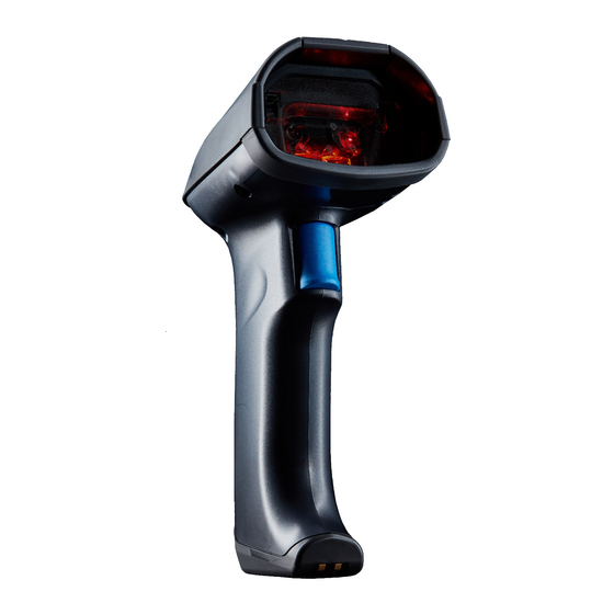
Chapter 1 Names and Functions Scanning window Hold this window over Beep emitter the code to be scanned. The beeper sounds when the scanner has scanned a code successfully. Refer to Section 8.1 for details. Indicator LED Illuminates in blue when the scanner has scanned a code successfully. -
Page 15: Chapter 2 Bluetooth ® Wireless Communication
® Chapter 2 Bluetooth wireless communication ® Appendix 3 for terms regarding Bluetooth wireless communication. ® 2.1 Enabling Bluetooth wireless communication When using the scanner for the first time, read the “Setting commencement” and “Start operation” QR codes (Section 13.2) following the procedure in Section 13.1. - Page 16 ® 2.2 Establishing Bluetooth wireless communication ® After the Bluetooth wireless communication function has been enabled, the descriptions in this section can be used to ® establish a Bluetooth wireless communication connection between the scanner and the BA series communications adapter or ®...
- Page 17 Connecting the scanner as a master device ® When using the scanner as the master device and a communications adapter or commercial Bluetooth device, etc. as the ® slave device, the Bluetooth address of the connecting slave device must be set on the scanner. Refer to the examples below. The connection between the scanner and the slave device is a 1:1 connection.
- Page 18 Connecting the scanner with an iPhone, iPad, Android, PC or other device ® To connect the scanner to a iPhone, iPad, Android device, PC, or other device equipped with a Bluetooth Specification Ver. ® 2.1+EDR-compatible Bluetooth module, the following settings are required. ®...
- Page 19 ® Bluetooth -disconnect scanning ® Scanning is possible when Bluetooth wireless communication has been disconnected. This function is used when scanning a code will suffice and data transfer is not necessary. For example, it can be used in data verification mode for scanner-only determination without sending verification results to the host computer.
- Page 20 ® 2.4 Reconnecting Bluetooth wireless communication ® When Bluetooth wireless communication has been disconnected using the operation below, pull the trigger switch to reconnect. Wireless communication is reconnected if the scanner is the master device; the scanner waits for a connection request from the master device if it is the slave device.
-
Page 21: Chapter 3 Scanning Method
Chapter 3 Scanning Method 3.1 Before Use When using the scanner for the first time or when the scanner has not been used for a long period of time, always charge the battery before use. (See Chapter 10 for charging methods.) 3.2 Operating Procedure (1) Place the scanning window over the code, and pull the trigger switch. - Page 22 Scanning mode Regular scanning mode The data is transferred once the code has been read correctly. Data verification mode The data of the code that has been scanned is compared with that of the registered code to verify whether they match. Refer to Section 7.1 for details.
-
Page 23: Chapter 4 Parameter Settings
Chapter 4 Parameter Settings With this scanner, communication, code types and other parameters can be set using one of two methods, the QR-coded parameter menu or the configuration software (ScannerSetting_2D).* The set parameter values will be retained even after the scanner is turned off. -
Page 24: Chapter 5 Scanning Control
Chapter 5 Scanning Control Scanning can be controlled through two different methods, “scanning using the trigger switch” (Section 5.1), or “scanning using software control” (Section 5.2). “Scanning using the trigger switch” enables the user to scan by operating the trigger switch. - Page 25 (6) Continuous Reading Mode 2 Similar to continuous reading mode 1. The difference between this and continuous reading mode 1 is that the scanner enters standby state when scanning is complete. To return to the Active state, the scanner must first receive a “Z”, “READOFF” or “LOFF” command and enter the Ready state, and then receive an”R”, “READON”...
-
Page 26: Scanning Using Software Control
5.2 Scanning Using Software Control Instead of pulling the trigger switch to carry out scanning operations, these can be carried out via communication from a computer or other control device. These software control commands are affected by the trigger switch operation mode as shown in the table below. (Refer to Appendix 2: Control Commands for detailed control commands.) Trigger switch operation mode... -
Page 27: Scanning Through Automatic Label Recognition
5.3 Scanning through Automatic Label Recognition In auto sensing mode (including auto sensing operation in auto stand mode) there is no need to operate the trigger switch; approach the scanner with the code and the illumination light comes on making scanning available. This mode is used when the scanner is sitting in the stand and the codes are brought up to the scanner for scanning. -
Page 28: Chapter 6 Magic Key
Chapter 6 Magic Key The magic key can be used as an auxiliary key for scanning or data transfer. One of the following seven functions can be assigned to the magic key. It is also possible to select to ignore this function. Using the configuration software (ScannerSetting_2D), select the function that best suits your needs. - Page 29 The table below illustrates the relationship between magic key operation functions and trigger switch operation modes. (Identical for regular scanning mode and data verification mode.) An × in the table below indicates that the magic key operation function is deactivated. For example, even if the scanning active/ready switching function has been set on the magic key, it will be ignored while in auto-off mode.
- Page 30 ® Bluetooth wireless communication disconnection ® ® After establishing a Bluetooth wireless link, Bluetooth wireless communication can be disconnected by holding the magic key for two seconds or more. However, if the scanner is operating in data verification mode (excluding 2-point verification), wireless communication ®...
-
Page 31: Chapter 7 Scanning Function
Chapter 7 Scanning Function 7.1 Data Verification Mode When placed in data verification mode, the data of the code that has been scanned is compared with that of the master data to verify whether they match. Two data verification modes, “n-point verification” and “2-point verification,” are available. Make a selection in the configuration software (ScannerSetting_2D). - Page 32 Note: Control commands cannot be used when HID (Human Interface Device Profile) is selected. Note: Registered master data will be cleared in the following instance. ・ If parameter settings are changed using the configuration software (ScannerSetting_2D), batch setting QR Code, or QR-coded parameter menu. Note: Master data can be registered an unlimited number of times while the magic key is pressed and the indicator LED is illuminated in green.
-
Page 33: Designating Targets For Data Verification
7.1.2 Designating Targets for Data Verification When designating a data verification target, “data string” or “data block” can be selected. “Data string” refers to a data area specified by the verification start position and the number of verification digits. “Data block” refers to a CSV formatted data block separated by commas. -
Page 34: Verification Result Output
7.1.3 Verification Result Output (1) Verification Result Based Data Output One of the following three data output patterns can be selected in the configuration software (ScannerSetting_2D) for each of the two possible results, “verification matched” and “verification mismatched”. No output will occur if “Transfer disabled” is selected. Verification matched Verification mismatched Transfer disabled... -
Page 35: Data Edit Mode
7.2 Data Edit Mode The scanned code data can be edited and output in the following modes: “Data extraction mode,” “data conversion mode,” “block sorting mode,” and “ADF script mode”. These data editing modes can be set using the configuration software (ScannerSetting_2D). -
Page 36: Data String Extraction Mode
7.2.1.1 Data String Extraction Mode The scanner extracts the portion of data specified by the “extraction start position” and “extraction end position” from the code specified in the parameter “code type” and outputs it in the specified data transmission format (refer to Section 9.4). - Page 37 Extraction start position, Extraction end position Extraction start position Extraction end position First character Position specified/To the nth digit Last character Last character Number of digits specified/n Position specified/From the nth digits worth digit Position specified/To the nth digit n can be set within a range of 1 and 9999.
-
Page 38: Data Block Extraction
7.2.1.2 Data Block Extraction If the scanned data is CSV formatted data separated by commas, the scanner extracts data blocks specified by the “extraction block number” from codes specified in the parameter code type and outputs these data blocks in the data transmission format (refer to Section 9.4) selected in the scanner. - Page 39 Example: A QR Code with the following data is scanned. Header: STX, Terminator: ETX, Scanner ID: Prohibited, Code mark: Disabled, The Number of Digits: Disabled, Prefix/Suffix transmission: Not specified, BCC transmission: Disabled Parameters Scanned data Extraction block Output data [STX]1[ETX][STX]23[ETX][STX]45 1,23,456,7890 1 2 3 6[ETX]...
-
Page 40: Ai (Application Identifier) Extraction
7.2.1.3 AI (Application Identifier) Extraction When the scanned code is a GS1-128, GS1 DataBar, or GS1 Composite (excludes linear components of UPC/EAN Composite) code, the scanner edits the data using AI (Application Identifier) and outputs scanned data in the data transmission format (refer to Section 9.4) selected in the scanner in accordance with the specified parameters. - Page 41 Example: Scanned data: “(01)94901234567894(11)030808(13)030810(17)040208(17)040305” Header: STX, Terminator: ETX, Scanner ID: Prohibited, Code mark: Disabled, The number of digits: Disabled, Prefix/Suffix transmission: Not specified, BCC transmission: Disabled Specified Parameters Delimiters Output data 01,11,17 [STX]94901234567894,030808,040208[ETX] 17,11 [STX]040208,030808[ETX] Transmit data 17,17 [STX]040208,040305[ETX] regardless of the results: Error Disabled...
- Page 42 (2) AI Parenthesis Mode The scanner encloses the AI in parentheses and outputs the data in accordance with the specified parameters. Parameters Parameters Value Transmit data regardless of the results Enabled/Disabled When “Transmit data regardless of the results” is enabled, the scanned data will be output without editing if AI extraction fails.
- Page 43 (3) AI Table In “AI (Application Identifier) extraction” data is edited according to the AI defined in the table below. Number of Description digits n2+n18 Serial Shipping Container Code (SSCC) n2+n14 Global Trade Item Number (GTIN) n2+n14 GTIN of Contained Trade Items (must be processed with AI37) n2+n14 Reserved n2+n16...
- Page 44 Number of Description digits 320n n4+n6 Net weight, Pounds (***) 321n n4+n6 Length or first dimension, Inches (***) 322n n4+n6 Length or first dimension, Feet (***) 323n n4+n6 Length or first dimension, Yards (***) 324n n4+n6 Width, diameter, or second dimension, Inches (***) 325n n4+n6 Width, diameter, or second dimension, Feet (***)
- Page 45 Number of Description digits 353n n4+n6 Area, Square inches, Logistic Measures (***) 354n n4+n6 Area, Square feet, Logistic Measures (***) 355n n4+n6 Area, Square yards, Logistic Measures (***) 356n n4+n6 Net weight, Troy ounces (***) 357n n4+n6 Net weight (or volume), Ounces (***) 360n n4+n6 Net volume, Quarts (***)
- Page 46 Number of Description digits n3+n3+an..9 Ship to - Deliver to Postal Code with Three-Digit ISO Country Code n3+n3 Country of Origin of a Trade Item n3+n15 Country of Initial Processing n3+n3 Country of Processing n3+n3 Country of Disassembly n3+n3 Country Covering Full Process Chain n2+n4+n7+an..
- Page 47 Number of Description digits n2+an..30 Company Internal Information n2+an..30 Company Internal Information n2+an..30 Carrier Internal Information n2+an..30 Carrier Internal Information n2+an..30 Company Internal Information n2+an..30 Company Internal Information n2+an..30 Internal Information DD is “00” when displaying the year and month only (**) “n”...
-
Page 48: Data Conversion Mode
7.2.2 Data Conversion Mode In data conversion mode, when a code specified in the parameter “code type” is scanned in, the scanner searches for and converts the characters for conversion (up to 16 ASCII characters), and outputs the data in the data transmission format (refer Section 9.4) set by the scanner. -
Page 49: Block Sorting Mode
7.2.3 Block Sorting Mode The scanner splits a code specified in the parameter “Code type” at the specified position(s) (max. five divisions), and sorts these data blocks into the specified output sequence for output in the transmission format (refer to Section 9.4) specified by the scanner. -
Page 50: Adf Script Mode
7.2.4 ADF Script Mode ADF script is a simple programming language used to edit scanned data. The main functions of ADF script are listed below. (1) Fixed/variable length data extraction (2) GS1-128, GS1 DataBar, GS1 Composite AI (Application Identifier) compatibility (3) Sorting disordered data into the prescribed order (4) Data verification (5) Repeated output of the same data... -
Page 51: Barcode Reader Mode
7.3 Barcode Reader Mode In barcode reader mode, the scannable range on the longitudinal scale is limited to the central 15% shown in the figure below, with a skew angle diameter of 5°≧θ≧-5°. Less time is therefore required for barcode scanning than standard reader mode. 2-D codes and multi-line barcodes cannot be scanned in this mode, even if scanning of these codes is enabled. -
Page 52: Split Qr Code Scanning
7.7 Split QR Code Scanning With QR Code models 1 and 2, and iQR Codes, the data can be split into a maximum of 16 codes for processing as individual split codes. Split codes can only be scanned by the same model. For split code scanning, use the QR-coded parameter menu or configuration software (ScannerSetting_2D) to select either “edit mode,”... -
Page 53: Multi-Line Barcode Scanning
7.8 Multi-line Barcode Scanning The scanner is capable of scanning up to three lines of barcodes within its scanning field at a single time. Use the configuration software (ScannerSetting_2D) to specify the number of lines, data output order, and output format of the multi-line barcode to be scanned. -
Page 54: Chapter 8 Beeper, Indicator Led, Vibrator, Marker, Illumination Light
Chapter 8 Beeper, Indicator LED, Vibrator, Marker, Illumination Light 8.1 Beeper (1) Beeper Sound The beeper emits a single or multiple long or short beeps according to the various conditions. The beeper emits a short beep when - the code has scanned successfully, - the scanned code data matches the master data in “data verification mode,”... - Page 55 Use the configuration software (ScannerSetting_2D) to enable/disable the beeper sound when the scanner is turned on (Default: disabled). The beeper tone cannot be changed. Beeper sound can be disabled using the QR-coded parameter menu or the configuration software. In the following instances, however, the beeper sounds regardless of that beeper setting: - when the scanner is customized with the QR-coded parameter menu (Chapter...
-
Page 56: Indicator Led
8.2 Indicator LED The indicator LED illuminates or flashes in blue, green, red or orange as described below. The indicator LED illuminates in blue when: - the code has scanned successfully, - a split QR Code is scanned, - the scanned code matches the master data in “data verification mode,” or - the master data has been registered successfully in “data verification mode”. - Page 57 The indicator LED flashes in orange when: - the battery level of the rechargeable battery cartridge is low (long flashes), or - the scanner is going to turn off due to the low battery level of the rechargeable battery cartridge (five short flashes). The indicator LED flashes in blue when: - the scanner commences or completes reading from the QR-coded parameter menu (Chapter...
-
Page 58: Vibrator
8.3 Vibrator Use the QR-coded parameter menu or the configuration software (ScannerSetting_2D) to select whether the scanner will vibrate when an “OK” action occurs or when the action is “NG”. There are settings for disabling vibrator operation. If OK vibration is enabled, the scanner will vibrate when: - the scanned data has been transferred successfully, - the scanned code data matches the master data in “data verification mode,”... -
Page 59: Marker
8.4 Marker The red semiconductor laser illuminates to indicate the scanning area as a guide. Using the QR-coded parameter menu or configuration software (ScannerSetting_2D), select one of the three following modes. 8.4.1 Normal Marker Mode When the trigger switch is in auto-off mode or auto stand mode auto-off The marker beam illuminates continuously while the trigger switch is held down. -
Page 60: Illumination Light
8.5 Illumination Light The illumination LEDs light up when the scanner is in the Active state. Using the configuration software (ScannerSetting_2D), illumination lights can be turned on or off. When the illumination LEDs are on, it is possible to activate an “ECO mode” which controls the brightness of the LEDs and reduces electrical consumption by 20%. -
Page 61: Chapter 9 Communication
Chapter 9 Communication ® 9.1 Bluetooth Interface Use the QR-coded parameter menu or the configuration software (ScannerSetting_2D) to set the communications conditions. Scanned data can be transmitted to external devices or computers in the following formats. The waiting time for a connection from a master device when the scanner is the slave device can be selected from 2 minutes (default), 4 minutes, 10 minutes, and 30 minutes. -
Page 62: Hid Profile
9.3 HID Profile The scanner supports Human Interface Device Profile (HID profile), which can connect to an iPhone, iPad, Android device, ® ® PC, or other device equipped with a Bluetooth Specification Ver. 2.1+EDR-compatible Bluetooth module. (1) Caps Lock Status Align with the Caps Lock status of the host computer. -
Page 63: Communication Format
9.4 Communication Format Select the data communication format from the following two options. Number of digits Code Scanner Header Prefix Code data Suffix Terminator mark n1 n2 n3 n4 Number of digits Code Scanner Header Prefix Code data Suffix Terminator mark n1 n2 n3 n4 Each item is described as follows:... - Page 64 (5) Code Mark This optional field specifies the code system. Code marks can be selected from the types (Type 1, Type 2, Type 3, Type 4, and user-defined) listed below. 2 output modes are available for Type 4 code marks: Coupling and separating. Coupling: Assigns a single code mark to the combination of the main symbol of barcodes with UPC/EAN add-on + add-on component.
- Page 65 Code mark Code Type Type1 Type2 Coupling Separating Coupling Separating Without add-on Linear With 2-digit add-on EAN-13 Add-on None None Linear With 5-digit add-on Add-on None None Without add-on Linear With 2-digit add-on EAN-8 Add-on None None Linear With 5-digit add-on Add-on None...
- Page 66 Code mark Code Type Type1 Type2 Coupling Separating Coupling Separating GS1 DataBar GS1 DataBar CC-A (Note 1) GS1 DataBar CC-B (Note 1) CC-A, CC-B None None (Note 2) (Note 2) Without add-on Linear With 2-digit add-on UPC-A Add-on None None None None UPC-A CC-A,...
- Page 67 Code mark Code Type Type3 Type 4 (Note 3) Coupling Separating Coupling Separating QR code Edit mode QR code Batch edit mode (Split mode) Non-edit mode (Note 4) Micro QR code (Note 4) SQRC (Note 4) iQR code Edit mode iQR code (Split mode) Non-edit mode...
- Page 68 Code mark Code Type Type3 Type 4 (Note 3) Coupling Separating Coupling Separating Interleaved 2 of 5 Standard 2 of 5 (short) Standard 2 of 5 (normal) Code 39 Code 39 Full ASCII Codabar (NW-7) Code 128 GS1-128 Code 93 GS1 DataBar (Note 1) GS1 DataBar...
- Page 69 Note 1: “GS1 DataBar” refers to all of the following codes: GS1 DataBar Omnidirectional, GS1 DataBar Truncated, GS1 DataBar Limited, GS1 DataBar Stacked, GS1 DataBar Expanded, GS1 DataBar Stacked Omnidirectional, GS1 DataBar Expanded Stacked Note 2: These code marks are contained in the code data. Note 3: Type 4 code mark is a code mark system that conforms to the AIM USA “Guidelines on Symbology Identifiers.”...
- Page 70 (6) Number of Digits This optional field specifies whether to transmit the number of digits of code data. The default setting is transfer disabled. When transmission is enabled, select between four digits (4 bytes) or two digits (2 bytes). The number of digits will be omitted for the UPC and EAN codes.
- Page 71 UPC-A You can select whether or not to transmit the padding character “0”, number system character “S”, and the check digit to the host. Disabling the transmission of the number system character “S” automatically disables the transmission of the padding character “0”.
- Page 72 With UPC-E Add-on If the scanner is set to “Code mark type: Type 4,” and “Code mark output mode: Separating,” a code mark will be applied in front of the add-on code data. (For details on the code mark applied, refer to Section 9.4 (5)) You can also select whether or not to convert to GTIN format and UPC-A.
- Page 73 With EAN-13 Add-on: If the scanner is set to “Code mark type: Type 4,” and “Code mark output mode: Separating,” a code mark will be applied in front of the add-on code data. (For details on the code mark applied, refer to Section 9.4 (5)) You can also select whether or not to convert to GTIN format.
- Page 74 Code 39 The scanned data is transmitted as is. You can select whether or not to transmit the start-stop codes. Start-stop codes are “*”. Interleaved 2 of 5, Standard 2 of 5 The scanner transmits scanned code data, starting from the character following the start code to the one preceding the stop code.
- Page 75 Composite with UPC/EAN Add-on The scanned data is transmitted as is. If the scanner is set to “Code mark type: Type 1” and “Code mark output mode: Separating,” a separator <GS> (1Dh) and 2D code mark will be applied between the linear code data and 2D code data. If the scanner is set to “Code mark type: Type 4”...
-
Page 76: Gtin Conversion
9.5 GTIN Conversion When GTIN (Global Trade Item Number) format is enabled, UPC-A, UPC-E, EAN-13, EAN-8, and Interleaved 2 of 5 (14 digits) formats can be converted to GTIN for output. GS1 DataBar, GS1-128 in GTIN format can also be outputted in product code (EAN-13/JAN-13) format. - Page 77 With UPC-A Add-on - Scanned data With 2-digit add-on: 0 S X C/D X With 5-digit add-on: 0 S X C/D X Padding character for adjustment of the data length Number system character Add-on code data 11-15 - Conversion to 16 digits (the application identifier “01” and PI are added at the start of the code before transmission) With 2-digit add-on: 0 1 PI 0 S X C/D X...
- Page 78 With UPC-E Add-on - Scanned data With 2-digit add-on: C/D X With 5-digit add-on: C/D X Padding character for adjustment of the data length Add-on code data 7-11 - Conversion to 16 digits (the application identifier “01” and PI are added at the start of the code before transmission) With 2-digit add-on: =0-2 0 1 PI 0 S X...
- Page 79 With EAN-13 Add-on: - Scanned data With 2-digit add-on: C/D X With 5-digit add-on: C/D X Prefix character Add-on code data 10-14 - Conversion to 16 digits (the application identifier “01” and PI are added at the start of the code before transmission) With 2-digit add-on: 0 1 PI P C/D X...
- Page 80 With EAN-8 Add-on: - Scanned data With 2-digit add-on: C/D X With 5-digit add-on: C/D X Prefix character Add-on code data 6-10 - Conversion to 16 digits (the application identifier “01” and PI are added at the start of the code before transmission) With 2-digit add-on: 0 1 PI 0 0 0 0 0 P C/D X...
- Page 81 (2) Converting GS1 DataBar and GS1-128 in GTIN Format to ENA/JAN You can select whether or not to convert scanned GS1 DataBar or GS1-128 in GTIN format (16 digits with application identifier “01”) to EAN/JAN format. Choose from conversion to 13-digit EAN/JAN format (the application identifier “01” and PI at the start of the code are not transmitted) or conversion to 14-digit EAN/JAN format (the application identifier “01”...
-
Page 82: Data Packing (Data Packetizing)
9.6 Data Packing (data packetizing) Data packing (data packetizing) is used when the user wants to increase the reliability of wireless communication. With data packing, data being sent via wireless communication is first converted to the following formats (packetized) before being sent. - Page 83 Note: If the DLE (10h) is included in data other than the header or terminator, the DLE is applied to the front of the header before the data is transferred. When performing data packing (data packetizing) using a device other than the communications adapter, the applied DLE must be deleted by CRC calculation and retrieving the transferred data.
- Page 84 - Scanner setting ・ Data packing (host) (1) Data packetized and sent (2) Received packet analyzed (3) ACK is sent when data is received successfully; NAK is sent if not successfully Bluetooth® device or personal computer with received Bluetooth® functionality ...
-
Page 85: Chapter 10 Rechargeable Battery Cartridge Charging And Replacement
Chapter 10 Rechargeable Battery Cartridge Charging and Replacement A warning beep will sound when the battery level of the rechargeable battery cartridge becomes low. When the warning beep sounds, charge the rechargeable battery cartridge. While charging, it is normal for the scanner body and the battery charger to become hot. 10.1 Rechargeable Battery Cartridge Charging Method Indicator Scanner... - Page 86 Charging method (1) Connect the AC adapter to the battery charger before inserting it into the socket. Confirm that the battery charger's power LED (green) is illuminated. (2) Set the scanner on the battery charger. Charging begins when the scanner indicator LED illuminates in red. Charging time is approximately 2.5 hours.
-
Page 87: Rechargeable Battery Cartridge Replacement Method
10.2 Rechargeable Battery Cartridge Replacement Method When the time in which the scanner can be used becomes noticeably shorter despite charging the rechargeable battery cartridge, replace the rechargeable battery cartridge. Note: The rechargeable battery cartridge is perishable and as such its life is limited. The length of its life depends on the usage conditions. - Page 88 (5) Connect the cable of the new rechargeable battery cartridge to the battery cable connector. (6) Insert the new rechargeable battery cartridge into the scanner. (7) After guiding the cable into the space around the rechargeable battery cartridge, close the lower housing and tighten the screw.
-
Page 89: Recycling The Rechargeable Battery Cartridge
● Please take any expended rechargeable battery cartridge to your nearest cooperating rechargeable battery recycler, or contact your nearest Denso office. Pay careful attention to the following points when placing the used rechargeable battery cartridge into the recycling box of a recycler. -
Page 90: Chapter 11 Image Capture Function
Image Capture Function 11.1 Function Outline The GT20Q-SB scanner is equipped with an image capture function. Scanned images can be output in either BMP (bitmap file) format or as a JPEG (standard, high, or low quality). Image size can be selected from Standard WVGA, 1/4 WVGA and 1/16 WVGA. When 1/4 WVGA or 1/16 WVGA is selected, users can select whether to enlarge the image to fit the screen, or to extract the center portion of the full screen (1/1WVGA). - Page 91 (4) Image Output Setting Command IMAGEOUT#1#m#n.......... Thumbnail transmission is enabled IMAGEOUT #1#m#n#o ..Thumbnail transmission is disabled The details of the four parameters are as follows: 1: Output format (file type) BMP format J or J0 JPEG format (standard) JPEG format (high quality) JPEG format (low quality) M: Image Size Standard WVGA...
- Page 92 (6) Note: - Only control commands can be used to enable image transmission. There is no setting to initiate it in the QR Menu. - During image transmission mode, scanning of barcodes or 2D codes, etc. is disabled. Further, the protocol is fixed as Xmodem 1K.
-
Page 93: Chapter 12 Settings Overview And Factory Settings
Chapter 12 Settings Overview and Factory Settings The following parameters can be selected via the QR-coded parameter menu or configuration software (ScannerSetting_2D). However, the parameters in the shaded boxes can only be set via the configuration software. At the time of shipping, all settings are set to the factory defaults. - Page 94 ® (3) Bluetooth Communications Parameters Specification (when SPP profile set) Settings Parameters Default Refer to Non-acknowledge mode ACK/NAK mode (host) Communication procedures Data packing mode (host) Section 9.2 Data packing mode (BA series) Set range 0.1 - 9.9 s ACK/NAK response verification time : Only available via configuration software.
- Page 95 Settings Parameters Default Refer to Enabled Special key transmission mode (Note 1) Disabled 0 ms 1 ms 10 ms 15 ms Data transmission interval 30 ms 50 ms 100 ms Enabled Software keyboard Section 2.2 Disabled : Only available via configuration software. Note 1: It is possible to select whether or not special keys are transmitted for sections of data other than the communication format header/terminator.
- Page 96 ® (5) Bluetooth Communications Parameters Specification Settings Parameters Default Refer to Master mode ® Bluetooth wireless communication Slave mode Section 2.2 connection No change Address Connecting device when master Section 2.2 Local name Address of connecting device Not specified Specify address of connecting device Section 2.2 ...
- Page 97 (7) Data Transmission Format Specification (when HID profile set) Settings Parameters Default Refer to None CR+LF Header ENTER Execute (right CTRL) ← ↑ → ↓ User selection Section 9.4 (1) None CR+LF Terminator ENTER Execute (right CTRL) ← ↑...
- Page 98 (8) Data Transmission Format Specification Settings Parameters Default Refer to Transmission enabled Code mark transmission Section 9.4 (5) Transfer disabled Before the prefix Code mark addition position Section 9.4 After the prefix Type1 Type2 Type3 Code mark types Section 9.4 (5) Type4 User selection...
- Page 99 (9) Specifying 2D Codes, Mirror Images, Black-and-white Inverted Codes, and SQRC Settings Parameters Default Refer to Enabled Mirror image 2D code scanning Section 7.5 Disabled Black-and-white normal code Black-and-white inverted code Black-and-white inverted code Section 7.6 scanning Black-and-white auto-detect ...
- Page 100 Settings Parameters Default Refer to Enabled (SQRC and QR Code) Only SQRC scanning enabled SQRC scanning Disabled Scanning disabled SQRC encryption key mismatch Section 7.9 processing Transmission of disclosed data only Transmission of disclosed data and SQRC encryption key match undisclosed data processing Transmission of undisclosed data only...
- Page 101 (10) Barcode Specification UPC-A/E, EAN-13/8 Settings Parameters Default Refer to Enabled UPC-A, EAN-13 scanning Disabled Transmission enabled UPC-A C/D transmission Transfer disabled Transmission enabled UPC-A number system character transmission Transfer disabled Section 9.4 (7) Transmission enabled Transmission of UPC-A padding characters for adjustment of the data Transfer disabled...
- Page 102 Settings Parameters Default Refer to Enabled EAN-8 code scanning Disabled Transmission enabled EAN-8 C/D transmission Transfer disabled Conversion enabled EAN-8 EAN-13 conversion Conversion disabled Enabled UPC/EAN add-on 2-digit scanning Disabled Section 9.4 (7) Enabled UPC/EAN add-on 5-digit scanning ...
- Page 103 Standard 2 of 5 Settings Parameters Default Refer to Scanning enabled (without check digit) Scanning enabled (with check digit) (check digit transmission enabled) Standard 2 of 5 scanning Scanning enabled (with check digit) (check digit transmission disabled) Disabled Standard 2 of 5 minimum scannable 3 digits digits 3-99 digits...
- Page 104 Code 39 Settings Parameters Default Refer to Scanning enabled (without check digit) Scanning enabled (with check digit) (check digit transmission enabled) Code 39 scanning Scanning enabled (with check digit) (check digit transmission disabled) Disabled 3 digits Code 39 minimum scannable digits 3-99 digits(incl.
- Page 105 Code 93 Settings Parameters Default Refer to Enabled Code 93 scanning Disabled 1 digit Code 93 minimum scannable digits 1-99 digits (excl. start-stop code and (Note 1) 2-digit check digit) 99 digits Code 93 maximum scannable digits : Only available via configuration software. Note 1: The parameter setting range and the number of scannable digits differ.
- Page 106 Settings Parameters Default Refer to Enabled GS1 DataBar Composite (with CC-B) scanning Disabled Enabled EAN/UPC Composite (with CC-A) scanning Disabled Enabled EAN/UPC Composite (with CC-B) scanning Disabled (Note 1) Enabled GS1-128 Composite (with CC-A) scanning Disabled Enabled GS1-128 Composite (with CC-B) ...
- Page 107 (11) Trigger Switch/Magic Key Control Settings Parameters Default Refer to Auto-off mode Momentary switching mode Momentary switching mode (reverse type) Section 5.1 Alternate switching mode Trigger switch control Continuous reading mode 1 Continuous reading mode 2 Auto sensing mode Section 5.3 Auto stand mode ...
- Page 108 Settings Parameters Default Refer to Scanning code switching function Data retransfer function Specific character transfer function Scanning active/ready switching function Magic key control Chapter 6 Marker switching function Barcode reader mode switching function Auto sensing mode switching function No function assigned ...
- Page 109 (12) Beeper, Indicator LED, Vibrator, Marker, Illumination Light Settings Parameters Default Refer to Enabled Beeper sound Disabled Low (approx. 2.5 kHz) Medium (approx. 3.0 kHz) Beeper tone High (approx. 3.5 kHz) Short (approx. 60 ms) Medium (approx. 80 ms) Beeper sounding time Long (approx.
- Page 110 Settings Parameters Default Refer to 001-999 digits Data string verification start position ASCII characters specified 01-99 digits Data string verification digits ASCII characters specified (without preset master registration) 01-99 digits Data block verification block position ASCII characters specified Transfer disabled Verification result transmission: Code data transmitted OK result...
- Page 111 Settings Parameters Default Refer to 01-99 digits No. of blocks in “data block specified ASCII characters specified extraction” (max. 3) Characters for conversion and Max. 16 characters ASCII characters conversion character specification in specified specified data conversion mode 2-5 divisions Block sorting mode division count divisions 0001-9999 characters...
-
Page 112: Chapter 13 Qr-Coded Parameter Menu
Chapter 13 QR-coded Parameter Menu 13.1 Setting Methods via the QR-coded Parameter Menu Scan the “Setting commencement” QR Code. Setting commencement ↓ The beeper will sound 3 times. Scan the QR Code you wish to set. Scanning parameter setting codes ↓... -
Page 113: Qr-Coded Parameter Menu
13.2 QR-coded Parameter Menu The following setting can be made just by scanning the QR codes with this parameter, without needing to scan the “Setting commencement” or “Setting completion” QR codes. Easy connection setting Scanning the following QR codes will allow the user to easily set a connection suited to the device being connected. - Page 114 ■ Setting Commencement, Setting Completion, Defaults Setting commencement Setting commencement Cancel All Default Setting completion...
- Page 115 ■ Bluetooth ® wireless communication Operation <Start operation> End operation Bluetooth® wireless communication disconnection ® Bluetooth -disconnect scanning ® ® Scanning the “Bluetooth -disconnect scanning” QR code allows scanning when Bluetooth wireless communication has been disconnected. In this state, data cannot be transmitted to or from the host computer. ®...
- Page 116 ■ Bluetooth ® wireless communications parameters specification Communication procedures <Non-acknowledge mode> ACK/NAK mode Header (when SPP profile set) <None> Header (when HID profile set) <None> Enter Terminator (when SPP profile set) None <CR> CR LF Terminator (when HID profile set) None <Enter>...
- Page 117 Connection standby time when slave <2 minutes> 4 minutes 10 minutes 30 minutes Keyboard-type (when HID profile set) <Japanese (106-key Keyboard)> U.S. English (101-key Keyboard) ■ Transmission Format Code mark transmission <Disabled> Enabled Digit no. transmission <Disabled> 2-digit transmission enabled 4-digit transmission enabled...
- Page 118 BCC transmission <Disabled> Enabled ■ Specifying 2D Code, Black-and-white Inversion Micro QR Code scanning <Enabled> Disabled Black-and-white inverted code scanning <Black-and-white normal code> Black-and-white inverted code Black-and-white auto-detect Split QR Code <Edit mode> Non-edit Mode Split QR Code batch edit...
- Page 119 PDF417 scanning <Enabled> Disabled MaxiCode scanning <Enabled> Disabled Data Matrix scanning Disabled <Enabled> ■ Scannable Barcode Settings UPC-A, UPC-E, EAN-13, EAN-8 scanning <Enabled> Disabled...
- Page 120 Interleaved 2 of 5 scanning Disabled Scanning with check digit enabled (Check digit transmission disabled) <Scanning without check digit enabled> Scanning with check digit enabled (Check digit transmission enabled) Code 128 (GS1-128) scanning <Enabled> Disabled Codabar (NW-7) scanning <Scanning without check digit enabled> Disabled Scanning with check digit enabled (Check digit Scanning with check digit enabled (Check digit...
- Page 121 Codabar (NW-7) start-stop code transmission <Enabled> Disabled Code 39 scanning <Scanning without check Disabled digit enabled> Scanning with check digit enabled (Check digit Scanning with check digit enabled transmission enabled) (Check digit transmission disabled) Code 39 start-stop code transmission <Disabled> Enabled Code 93 scanning <Disabled>...
- Page 122 GS1 DataBar scanning <Disabled> Enabled GS1 Composite scanning <Disabled> Enabled ■ Other Settings Trigger switch control <Auto-off mode> Alternate switching mode Momentary switching mode (reverse type) Momentary switching mode Continuous reading mode 1 Continuous reading mode 2 Auto stand mode Auto sensing mode...
- Page 123 ® Operation following Bluetooth disconnection via pressing the magic key <Reconnection by pulling the trigger Host connection standby switch> Beeper control Sound disabled <Sound enabled> Indicator LED Illumination disabled <Illumination enabled> Vibrator <Vibrates when “OK”> Vibrates when “NG” Vibration disabled ECO mode <Enabled>...
-
Page 124: Chapter 14 Qr-Coded Parameter Menu For Setting The Communications Adapter (Ba Series)
Chapter 14 QR-Coded Parameter Menu for Setting the Communications Adapter (BA Series) 14.1 Setting Methods via QR-coded Parameter Menu for Setting the Communications Adapter The user can set the communications adapter (BA11-RKU, BA20-RU) from the scanner by using the QR-coded parameter menu for setting the communications adapter. -
Page 125: Qr-Coded Parameter Menu For Setting The Communications Adapter
14.2 QR-Coded Parameter Menu for Setting the Communications Adapter ■ Setting Commencement, Setting Completion, Defaults Setting commencement Setting commencement Cancel All Default Setting completion ■ Specifying Interface <USB keyboard interface> RS-232C Interface USB-COM Interface... - Page 126 ■ Specifying Communications Parameters for the USB-COM Interface CTS control (USB-COM interface) <Controlled> Not controlled ■ Specifying RS-232C Interface Communications Parameters Transmission speed (RS-232C interface) 1200bps 2400bps <9600bps> 4800bps 14400bps 19200bps 38400bps 57600bps 115200bps...
- Page 127 Word length (RS-232C interface) 7 bits <8 bits> Parity(RS-232C interface) <Disabled> Even number Odd number Stop bit (RS-232C interface) <1 bit> 2 bits CTS signal control (RS-232C interface) <Controlled> Not controlled...
- Page 128 ■ Specifying Communications Parameters for the USB Keyboard Interface Specifying USB keyboard interface keyboard type (default) German <U.S. English> French U.K. English Italian Japan Swedish...
-
Page 129: Chapter 15 Simple Troubleshooting
Chapter 15 Simple Troubleshooting Problem 1: Cannot correctly scan code Things to check Measures Is the position of the scanner correctly aligned with Align the scanner correctly with the code. the code? Is the code obscured by dirt, etc.? Wipe away anything obscuring the code. Is the code blurred? Use a code that is not blurred. -
Page 130: Appendix 1: Specifications
(∗2) Applies to QR codes and Data Matrix. (∗3) Applies to codes other than GS1 Databar (∗4) Denso measured reference value - Battery type: Using a new, fully charged single-purpose lithium-ion battery cartridge - Connected to: BA series communications adapter (BA20-KU) - One code scanned every five seconds (∗5) Ensure that the wet-bulb temperature remains at 30℃... -
Page 131: Appendix 2: Control Commands
Appendix 2: Control Commands The commands which are transmitted between the host unit and the scanner through the communication line are called the control commands. Items set by control commands from the host unit overlap those indicated in “Parameter setting by QR Code parameter menu”. Designation by the control command prevails over that by the QR Code parameter menu (refer to Chapter 13). - Page 132 Direction Contents Command Scanner Host Blue LED indicator illumination The LED indicators illuminates in blue for approximately 500 ms LB (Note 2) within 100 ms after the command is received. Green LED indicator illumination The LED indicators illuminates in blue for approximately 500 ms LG (Note 2) within 100 ms after the command is received.
- Page 133 Transmission orientation Contents Control command Scanner Host Scan fail When set to Continuous reading mode 1 or 2, data is transmitted ERROR when scanner enters Ready state without completing scanning in Active state. Possible to select whether to transmit. Match Only if data output is set to “OK”...
- Page 134 (2) Commands consist of the command field and the option fields Direction Contents Command Scanner Host 1D code scanning configuration 2D code scanning configuration Note 1: Settings can be saved to the FLASH ROM via the “PW” command. Note 2: Configuration does not change if only the above command is sent. ■...
- Page 135 Scan code, Check digit, Minimum digits and Maximum digits must be set as shown on the table below. Minimum Maximum Scan code Readable codes Check digit number of number of digits digits UPC-A, UPC-E, EAN-8, EAN-13 UPC-A, UPC-E, EAN-8, EAN-13 UPC/EAN with Add-on (Note 2) Standard 2 of 5 (STF)
- Page 136 Example S,ANL • Readable code: UPC-A, UPC-E, EAN-8, EAN-13, Codabar (without check digit), Code 93 • Readable number of digits: Default S,INM,,NM,,I10N5,I20N12 • Readable code: Interleaved 2 of 5 (without check digit), Codabar (NW-7) (Check digitdisabled), Code 39 (Check digit enabled) •...
- Page 137 Scan code, code type, minimum version, maximum version must be set as shown on the table below. Alphabet Code Readable code Minimum version Maximum version Readable code symbol type Model 1 QR code Model 2 Micro QR code MaxiCode PDF417 PDF417 MicroPDF417 Square...
- Page 138 ® Appendix 3: Bluetooth Wireless Communication Glossary ® This section explains terms regarding Bluetooth wireless communication. ® ® Bluetooth address A 48-bit address to identify Bluetooth devices. ® (Bluetooth Device Address) ® ® The address is defined by the Bluetooth SIG of each Bluetooth device (BD_ADDR)
- Page 139 2D code handy scanner GT20Q-SB Manual December 2015 First Edition DENSO WAVE INCORPORATED AUTO-ID Business Unit...
- Page 140 1 Yoshiike, Kusagi, Agui-chô, Chita-gun, Aichi 470-2297, JAPAN http://www.denso-wave.com/...
Need help?
Do you have a question about the GT20Q-SB and is the answer not in the manual?
Questions and answers