Table of Contents
Advertisement
Quick Links
Advertisement
Table of Contents

Subscribe to Our Youtube Channel
Related Manuals for Denso GT10B-SM


Summary of Contents for Denso GT10B-SM
- Page 1 Bar Code Handy Scanner GT10B-SM / GT11B-SM GT10B-LM User's Manual...
- Page 2 If it is judged by DENSO WAVE INCORPORATED that malfunction of the product is due to the product having been dropped or subjected to impact, repairs will be made at a reasonable charge even within the warranty period.
-
Page 3: Table Of Contents
Contents Preface ..................................... SAFETY PRECAUTIONS.............................. ii Care and Maintenance ..............................v Chapter 1 Parts Names and Functions.......................... 1 Chapter 2 Preparation ..............................2 Connecting the Interface Cable to the Scanner ................... 2 Connecting the Scanner to Your Computer ....................3 Chapter 3 Reading Bar Codes ............................ - Page 4 Chapter 10 Communication............................33 10.1 RS-232C Interface ............................33 10.2 PS/2 Keyboard Interface..........................34 10.3 Communication Format ..........................34 10.3.1 Data transmission format ........................34 10.3.2 GTIN format conversion........................38 Chapter 11 Parameters and Defaults ..........................39 (1) Interface to the host ........................39 (2) Asynchronous data transmission (RS-232C interface) ..............
-
Page 5: Preface
Preface This user's manual sets forth the procedures for handling, connecting, operating, and cleaning your bar code handy scanner. Before you do anything else, study it carefully to make sure that you use the product both correctly and effectively. Also keep it handy for ready reference. -
Page 6: Safety Precautions
SAFETY PRECAUTIONS Be sure to observe all these safety precautions. Please READ through these instructions carefully. They will enable you to use the scanner correctly. Always keep this manual nearby for speedy reference. Strict observance of these warnings and cautions is a MUST for preventing accidents that could result in bodily injury and substantial property damage. - Page 7 To System Designers: • When introducing the scanner in those systems that could affect human lives (e.g., medicines management system), develop applications carefully through redundancy and safety design which avoids the feasibility of affecting human lives even if a data error occurs. •...
- Page 8 • Never disassemble or modify the scanner; doing so could result in an accident such as break or fire. Never Doing so could result in a fire or electrical shock. disassemble • Do not put the scanner on an unstable or inclined plane. The scanner may drop, creating injuries.
-
Page 9: Care And Maintenance
Limited Warranty on Software Products In no event will DENSO WAVE be liable for direct, indirect, special, incidental, or consequential damages (including imaginary profits or damages resulting from interruption of operation or loss of business information) resulting from... -
Page 10: Chapter 1 Parts Names And Functions
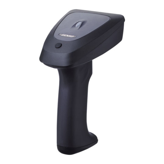
Chapter 1 Parts Names and Functions Indicator LED This turns blue after a successful read and red if there is an error. Reading window (Refer to Chapter 9 for details.) Point this at the bar code to read. Magic key This key functions as an auxiliary key for reads, data transfers, and the like. -
Page 11: Chapter 2 Preparation
Chapter 2 Preparation Connecting the Interface Cable to the Scanner (1) Pull the connector cover of the interface cable off its connector as shown below. (2) Plug the interface cable connector into the connector located in the bottom of the scanner. Note: As shown below, hold the scanner body, align the mark on the cable connector with that on the scanner, ▼... -
Page 12: Connecting The Scanner To Your Computer
Connecting the Scanner to Your Computer Using the RS-232C interface (1) Connect the RS-232C interface cable to your computer. AC adapter Scanner RS-232C interface cable (2) Plug the AC adapter into the DC power jack provided in the cable connector. (3) If the interface setting has been changed from the RS-232C interface (factory default) to the PS/2 keyboard interface, change it back to the RS-232C interface by scanning the following bar code: RS-232C interface... - Page 13 Using the PS/2 keyboard interface Note: Before proceeding to the connection procedure, be sure to switch off your computer. (1) The PS/2 keyboard interface cable is a Y-letter type having two connectors. Connect them to your computer and its keyboard as shown below. For a notebook or other computer with no external keyboard connected, simply plug the cable into the external keyboard connector.
-
Page 14: Chapter 3 Reading Bar Codes
Note: The effective scan range is less than the full illumination range. The effective scan range depends on the model and the distance from the scanner to the target. GT10B-SM/GT11B-SM: approximately 10 cm (3.94") for a scan distance of 7 cm (2.76") GT10B-LM: approximately 17 cm (6.69") for a scan distance of 18 cm (7.09") - Page 15 Reading RSS-14 Stacked and RSS-14 Stacked Omnidirectional symbols The scanner reads RSS-14 Stacked and RSS-14 Stacked Omnidirectional symbols in two steps. In the 1st step, it scans either one of the 1st and 2nd rows of the target symbol and accumulates the data in itself. In the 2nd step, it scans the remaining row, edits the 1st and 2nd row data read, and then sends the data to the host.
-
Page 16: Chapter 4 Customizing The Scanner
* Registered users can download the configuration software (ScannerSetting) from QBdirect, their customer support section on the Denso Wave website at no extra charge. For further details on QBdirect or to register, visit the following URL. -
Page 17: Chapter 5 Scanning Control
Chapter 5 Scanning Control Two types of scanning controls are available--Trigger switch control and Software control. Trigger switch control: Pressing the trigger switch readies the scanner for scanning. Software control: Instead of pressing the trigger switch, you send control commands from the host computer via the RS-232C interface to ready the scanner for scanning or put the scanner on standby. -
Page 18: Software Control
Software Control You can control the scanner by sending scanning control commands from the host computer via the RS-232C interface, instead of pressing the trigger switch. Scanning control commands include R, READON, LON, RC, Z, READOFF and LOFF and they are restricted by the trigger switch operating mode, as listed below. - Page 19 Failure read • Auto-off mode 1 Ready-to-scan command Command input (RxD) Bar code 1 to 5 sec. Illumination LEDs Failure notification Data output (TxD) • Momentary switching mode 1 Ready-to-scan command Command input (RxD) Standby command Bar code Illumination LEDs Failure notification Data output (TxD) (2) Continuous reading mode...
-
Page 20: Auto Sensing Mode-Automatic Detection Of Labels
Note: Given below is a guide for scanning EAN-13 symbols in auto sensing mode under these conditions: At the center of the effective scan range and at the ambient illuminance of 500 lux or higher. GT10B-SM/GT11B-SM: Scan distance of approx. 21 cm (8.27") GT10B-LM: Scan distance of approx. -
Page 21: Chapter 6 Magic Key Control
Chapter 6 Magic Key Control The magic key can act as an auxiliary key for scanning or data transfer. You can assign any of the following five functions or no function at all to the magic key. Select the function that best meets your needs using the bar-coded parameter menu or the configuration software (ScannerSetting). - Page 22 The following table lists the relationship between the magic key functions and trigger switch operating modes. (It applies to both the regular read mode and data verification mode.) The "--" indicates that the scanner ignores the magic key functions assigned. In auto-off mode 1, for example, the ready/standby switching function is ignored. Trigger switch operating modes Auto sensing Momentary...
-
Page 23: Chapter 7 Scanning Functions
Chapter 7 Scanning Functions Data Verification Mode The data verification mode verifies the bar code data read against the master data stored in the scanner and reports the match status with data output. Data verification read is available in two types--"n-point verification" and "2-point verification." Selecting the n-point verification requires registering master data only one time for 1:n verification. - Page 24 2-point verification read After registration of master data, the scanner reads a bar code, verifies the bar code data read against the master data and then becomes ready to register new master data. - Switch to the data verification mode. Use the bar-coded parameter menu or configuration software.
-
Page 25: Verification Conditions
7.1.2 Verification conditions You can set a verification starting position and the number of characters to check. - Starting position: The choices are 1st through 7th characters. - Number of characters: The choices are 1 through 7 and everything following the starting position (up to a maximum of 32 characters). -
Page 26: Verification Result Output
7.1.3 Verification result output (1) Report of match/mismatch status You can select any of the following report types by using the bar-coded parameter menu or configuration software (ScannerSetting). Selecting "Disable transmission" reports nothing. Setting If there is a match: If there is a mismatch: Disable bar code data transmission. -
Page 27: Specifying The Numbers Of Digits Of Standard 2Of5 And Interleaved 2Of5 Symbols To Read, By Scanning Bar Codes
Specifying the Numbers of Digits of Standard 2of5 and Interleaved 2of5 Symbols to Read, by Scanning Bar Codes You can specify the numbers of digits of Standard 2of5 and Interleaved 2of5 symbols to read. First enable the parameter "specification of the number of digits by bar code scanning" by using the bar-coded parameter menu or configuration software. -
Page 28: Chapter 8 Data Editing
Chapter 8 Data Editing The scanner can edit bar code data read in the format specified with the configuration software (ScannerSetting) and transfer it to the host computer. The format specification parameters retain their settings until the configuration software (ScannerSetting) or bar-coded parameter menu sets "All defaults."... -
Page 29: Substituting Data
(3) Extracting data from the specified start to tail positions The start position must be within the range from the 2nd to 99th digits. If the number of digits in bar code data read does not reach the specified start position, an error occurs. (Example) Start position Output data... -
Page 30: Blocksorting Data
(2) Transferring the substituted element string If the bar code data contains the specified substitution string within the specified search area, the scanner transfers the substituted element string followed by the bar code data read. (Example) Search start position Search string Substitution string Output data 2nd position... -
Page 31: Parenthesizing Ais (Application Identifier) In Ean-128 Data
Parenthesizing AIs (Application Identifier) in EAN-128 Data The scanner parenthesizes all AIs contained in EAN-128 data read and transfers the data. (For the definition of AIs, see Section 8.6.3.) The following sample bar code and scanner settings output data with AIs parenthesized as listed below. - Bar code sample Bar code type: EAN-128, Data read: 0194901234567894110308081303081017040208 - Scanner settings... -
Page 32: Data Editing Notes
(3) Tab (ASCII 09h <HT>) Specifying a tab as a delimiter outputs tab-delimited data. No tab follows the tail of the data. A header and terminator are added to the full string. A prefix, suffix, the number of digits, and code ID mark can be also added to the full string if their transmissions are enabled. -
Page 33: Ai Table
(12) Conversions apply to Codabar start/stop characters and include them in the number of digits. (13) Conversions force Codabar start/stop characters, if included in the output, to lower case. (14) Conversions skip Code 39 start/stop characters and do not include them in the number of digits. (15) The output never contains Code 39 start/stop characters regardless of their settings. - Page 34 Format Description n3+n..19 Batch or Lot Number (Transitional Use) (**) n3+an..30 Additional Product Identification Assigned by the Manufacturer n3+an..30 Customer Part Number n3+an..30 Secondary Serial Number n3+an…30 Reference to Source Entity n3+n27 Global Serial Number n3+n13+n..17 Global Document Type Identifier n2+n..8 Quantity 310n...
- Page 35 Format Description 345n n4+n6 Width, Diameter, or 2nd Dimension, Feet, Logistics (***) 346n n4+n6 Width, Diameter, or 2nd Dimension, Yards, Logistics (***) 347n n4+n6 Depth, Thickness, Height, or 3rd Dimension, Inches, Logistics (***) 348n n4+n6 Depth, Thickness, Height, or 3rd Dimension, Feet, Logistics (***) 349n n4+n6 Depth, Thickness, Height, or 3rd Dimension, Yards, Logistics (***)
- Page 36 Format Description Identification of a Physical Location--EAN.UCC Global Location n3+n13 Number n3+n13 EAN.UCC Global Location Number of the Invoicing Party n3+an..20 Ship to (Deliver to) Postal Code Within a Single Postal Authority Ship to (Deliver to) Postal Code with Three-Digit ISO Country Code n3+n3+n..9 Prefix n3+n3...
- Page 37 Format Description N2+an..30 Company Internal Information--Company N2+an..30 Company Internal Information--Carrier N2+an..30 Company Internal Information--Carrier N2+an..30 Company Internal Information--Company N2+an..30 Company Internal Information--Company N2+an..30 Company Internal Information To indicate only year and month, DD must be FILLED with "00." (**) n indicates the length of data. (***) n indicates the decimal point position.
-
Page 38: Chapter 9 Beeper, Indicator Led And Vibrator
Chapter 9 Beeper, Indicator LED and Vibrator Beeper (1) Beeping The scanner emits a short, long, one-shot, or intermittent beep to indicate the scanner status as described below. The intermittent and one-shot beeps apply when the scanner reads an RSS-14 Stacked or RSS-14 Stacked Omnidirectional symbol. - Page 39 One-shot beep* (40 ms) or intermittent beep* (at 60 ms intervals) when: • either one of the 1st and 2nd rows of an RSS-14 Stacked or RSS-14 Stacked Omnidirectional symbol is read. (Selecting an intermittent beep continues to beep as long as either one of the 1st and 2nd rows is left unread.) (Upon completion of a read, the beeper emits a short beep* The configuration software (ScannerSetting) provides three choices for the beeping time of a short beep--60, 80, and 120 ms.
-
Page 40: Indicator Led
Indicator LED The indicator LED lights or flashes in blue, green, red or orange to indicate the scanner status as described below. Lights in blue when: • a read of a bar code is successfully complete (Note that when the auto sensing mode switching function* is enabled, the indicator LED lights in green.), •... -
Page 41: Vibrator
Vibrator The bar-coded parameter menu and configuration software (ScannerSetting) provide three configuration choices: indicating successful scanning (OK), indicating an error (NG), and disabled. "OK" vibrations: The vibrator operates to indicate any of the following OK conditions. • Successful transmission of the bar code data just read •... -
Page 42: Chapter 10 Communication
Chapter 10 Communication 10.1 RS-232C Interface The scanner uses asynchronous data transmission and communicates with the connected host computer or external equipment via the RS-232C. You may set various communications conditions using the bar-coded parameter menu or configuration software (ScannerSetting). Bar code data read is transferred in the following format. (1) Communications protocol You can select either non-acknowledge mode or ACK/NAK mode. -
Page 43: Ps/2 Keyboard Interface
10.2 PS/2 Keyboard Interface This IBM PS/2 keyboard interface uses CMOS signal levels. (1) Keyboard connection type Select one of the following connection types according to your connection. Select: When the scanner is connected: "With external keyboard" (default) Between the desktop computer and its keyboard (excluding a numeric keypad). "Without external keyboard"... - Page 44 You can also select whether or not to transmit the code ID mark. (Default: No transmission) Code ID mark Bar code symbologies Type 1 Type 2 Type 5 Type 6 Type 3 Type 4 (DENSO 1) (DENSO 2) (AIM)* (AIM Type 2)* UPC-A UPC-E EAN-13 EAN-8 UPC-A with 2-digit add-on...
- Page 45 (4) Number of digits This optional field specifies the number of digits (2 or 4 digits) of bar code data to transmit or disables the transmission (default). Note that UPC and EAN codes (except EAN-128) skip this field. n1 : thousands (0 to 9) n2 : hundreds (0 to 9) n3 : tens (0 to 9) n4 : units (0 to 9)
- Page 46 Codabar (NW-7) Start code Data Stop code The Codabar symbology may or may not contain a check digit. You can select whether or not to check a check digit and transmit the check digit read. There are two check digit methods available: modulo arithmetic-16 (MOD-16) and 7-check method.
-
Page 47: Gtin Format Conversion
10.3.2 GTIN Format Conversion If the GTIN format conversion function is enabled, EAN-13, EAN-8, UPC-A, UPC-E and Interleaved 2of5 (14-digit) codes can be output in GTIN format, and GTIN format RSS and EAN-128 codes can be output by EAN/JAN (product code format). -
Page 48: Chapter 11 Parameters And Defaults
Chapter 11 Parameters and Defaults The tables below list the parameters and their defaults. Those parameter settings can be changed with the bar-coded parameter menu and configuration software (ScannerSetting), except shadowed ones only with the configuration software. When the scanner leaves the factory, all of these parameters are set to defaults. (1) Interface to the host Items Parameters... -
Page 49: Ps/2 Keyboard Interface
(3) PS/2 keyboard interface The following settings take effect when the PS/2 keyboard interface is used. Items Parameters Defaults Refer to: √ With external keyboard Keyboard connection type Section 10.2 (1) Without external keyboard With external numeric keypad √ OFF (Lowercase letter) Caps Lock of host's keyboard ON (Uppercase letter) Section 10.2 (2) - Page 50 Items Parameters Defaults Refer to: Enable Special key transmission (See Note 3.) √ Disable √ None CR LF Header Section 10.3.1 (1) ENTER Right Ctrl ← ↑ → ↓ User-defined (Note 3) Special key transmission applies to the fields except header and terminator in the data transmission format. Enabling this function substitutes E7h to FDh data with the special keys as listed below and transmits the substituted data to the host.
- Page 51 Items Parameters Defaults Refer to: None CR LF Terminator Section 10.3.1 (1) √ ENTER Right Ctrl ← ↑ → ↓ User-defined : Can be changed only with the configuration software.
-
Page 52: Data Transmission Format And Bar Code Symbologies
Transmission of code ID mark √ Disable Before prefix Code ID mark position √ After prefix √ Type 1 (DENSO 1) Section 10.3.1 (3) Type 2 (DENSO 2) Type 3 Code ID mark Type 4 Type 5 (AIM) Type 6 (AIM Type 2) - Page 53 UPC-A/E, EAN-13/8 Items Parameters Defaults Refer to: √ Enable Reading UPC-A, UPC-E, EAN-13 and EAN-8 Disable Enable Reading UPC/EAN with 2-digit add-on √ Disable Enable Reading UPC/EAN with 5-digit add-on √ Disable √ Enable Transmission of the number system character of UPC-A Disable √...
- Page 54 Standard 2of5 Items Parameters Defaults Refer to: Enable, without C/D Scanning Standard 2of5 Enable, with C/D √ Disable Minimum number of digits readable 3 digits for Standard 2of5 1 to 99 digits (See Note 5.) Maximum number of digits readable 99 digits for Standard 2of5 √...
- Page 55 Item Parameters Defaults Refer to: √ MOD-16 Check digit method for Codabar (NW-7) 7-check method Section 10.3.1 (5) Transmit a/b/c/d Transmission of start/stop codes Transmit A/B/C/D for Codabar (NW-7) √ Disable Code 32 Item Parameters Defaults Refer to: Enable Conversion from Code 39 to Code 32 format √...
- Page 56 Code 128, EAN-128 Items Parameters Defaults Refer to: √ Enable Scanning Code 128 Disable √ Enable Scanning EAN-128 Disable Minimum number of digits readable 1 digit for Code 128 and EAN-128 1 to 99 digits (See Note 5.) (excluding 1-digit C/D) Maximum number of digits readable 99 digits for Code 128 and EAN-128...
-
Page 57: Trigger Switch Control And Magic Key Control
(5) Trigger switch control and magic key control Items Parameters Defaults Refer to: Auto-off mode 1 Auto-off mode 2 √ Momentary switch mode 1 Trigger switch control Section 5.1 Momentary switch mode 2 Continuous reading mode Auto sensing mode 1 sec. 2 sec. -
Page 58: Beeper, Indicator Led And Vibrator
(6) Beeper, indicator LED and vibrator Items Parameters Defaults Refer to: √ Enable Beeper Section 9.1 Disable √ Short (60 ms) Beeping time of a short beep Section 9.1 Medium (80 ms) Long (120 ms) √ High Beeper volume Medium Section 9.1 Low (2.0 kHz) √... -
Page 59: Data Verification Mode
(7) Data verification mode Items Parameters Defaults Refer to: √ Regular read mode Scanning modes Data verification mode 2-point verification Data verification type √ n-point verification √ Disable Verification retry after mismatch in 2-point verification Enable √ Disable transmission/ Disable transmission Enable bar code data transmission/ Verification result output in data Disable transmission... -
Page 60: Speed-/Depth-Priority Scanning
Refer to: √ Speed-priority scanning Chapter 3 Speed-/depth-priority scanning (See Note 7.) √ Depth-priority scanning (Note 7) The default is speed-priority scanning for the GT10B-SM/GT11B-SM, and depth-priority scanning for the GT10B-LM. : Can be changed only with the configuration software. -
Page 61: Chapter 12 Bar-Coded Parameter Menu
Chapter 12 Bar-Coded Parameter Menu 12.1 Parameter Setting Procedure Using the Bar-Coded Parameter Menu Scan the "Start setting" bar code. "Start setting" ↓ Three beeps Scan desired parameter setting bar codes. Scan parameter setting NOTE: When using the bar-coded parameter menu, scan bar codes within three bar codes. -
Page 62: Bar-Coded Parameter Menu
12.2 Bar-Coded Parameter Menu Menu control (Starting/ending the setting procedure and reverting to defaults) Start setting End setting All defaults The beeper volume and interface items can be set by only scanning the following bar codes. No "Start setting" or "End setting"... -
Page 63: Communications Parameters For The Rs-232C Interface
Communications parameters for the RS-232C interface Communications protocol (RS-232C interface) Non-acknowledge mode (default) ACK/NAK mode RTS signal control mode (RS-232C interface) Scanner ready mode (default) Data ready mode CTS signal monitor (RS-232C interface) Enable Disable (default) Transmission speed (RS-232C interface) 1200 bps 2400 bps 4800 bps... - Page 64 Data bits (RS-232C interface) 7 bits 8 bits (default) Parity (RS-232C interface) Even None (default) Stop bits (RS-232C interface) 1 bit (default) 2 bits Header (RS-232C interface) None (default) Terminator (RS-232C interface) CR (default) CR LF None...
-
Page 65: Communications Parameters For The Ps/2 Keyboard Interface
Communications parameters for the PS/2 keyboard interface Keyboard connection type (PS/2 keyboard interface) With external keyboard (default) Without external keyboard With external numeric keypad Caps Lock of host's keyboard (PS/2 keyboard interface) Select the Caps Lock state that matches the host's keyboard state. OFF (default) Num Lock of host's keyboard (PS/2 keyboard interface) Select the Num Lock state that matches the host's keyboard state. - Page 66 Keyboard type (PS/2 keyboard interface) Select the type of the keyboard to be connected. U.S. English (101 Keyboard) (default) Germany (102 Keyboard) French (102 Keyboard) U.K. English (102 Keyboard) Italian (102 Keyboard) Swedish (102 Keyboard) Japanese (106 keyboard) IBM 5576-001 IBM 5576-002/003...
- Page 67 Header (PS/2 keyboard interface) None (default) CR LF ENTER Right Ctrl ← ↑ → ↓...
- Page 68 Terminator (PS/2 keyboard interface) None CR LF ENTER (default) Right Ctrl ← ↑ → ↓...
- Page 69 Data transmission interval (PS/2 keyboard interface) Select the data transmission interval according to the computer's processing speed. If bar code data is not displayed correctly (e.g., character missing), use a longer interval. 1 ms (default) 5 ms 10 ms 15 ms 30 ms 50 ms 100 ms...
-
Page 70: Data Transmission Format And Bar Code Symbologies
Enable Disable (default) Code ID mark position Before prefix After prefix (default) Code ID mark Type 1 (DENSO 1) (default) Type 2 (DENSO 2) Type 3 Type 4 Type 5 (AIM) Type 6 (AIM Type 2) Transmission of the number of digits (not applicable to UPC/EAN codes) - Page 71 UPC-A/-E and EAN-13/-8 Scanning UPC-A, UPC-E, EAN-13 and EAN-8 Enable (default) Disable Scanning UPC/EAN with Add-on Enable, no restriction on add-on digits Enable 5-digit add-on only Enable 2-digit add-on only Disable (default) Transmission of the number system character of UPC-A Enable (default) Disable Transmission of the number system character of UPC-E...
- Page 72 Transmission of the padding character "0" for the specified number of digits of UPC-E Enable Disable (default) Transmission of a check digit for UPC-A Enable (default) Disable Transmission of a check digit for UPC-E Enable (default) Disable Transmission of a check digit for EAN-13 Enable (default) Disable Transmission of a check digit for EAN-8...
- Page 73 Transmission format of EAN-8 (Conversion to EAN-13) Enable conversion Disable conversion (default) Transmission format of UPC-E (Conversion to UPC-A) Enable conversion Disable conversion (default) Transmission of country code for EAN-13 Enable (default) Disable Conversion to ISBN/ISSN format for EAN-13 Enable Disable (default) Standard 2of5 Scanning Standard 2of5...
- Page 74 Transmission of a check digit for Standard 2of5 Enable (default) Disable Specification of the number of digits for Standard 2of5, by bar code scanning Enable Disable (default) Interleaved 2of5 Scanning Interleaved 2of5 Enable, without C/D (default) Enable, with C/D Disable Transmission of a check digit for Interleaved 2of5 Enable (default) Disable...
- Page 75 Codabar (NW-7) Scanning Codabar (NW-7) Enable, without C/D (default) Enable, with C/D Disable Transmission of a check digit for Codabar (NW-7) Enable (default) Disable Calculation method for a check digit of Codabar (NW-7) MOD-16 (default) 7-check method Transmission of start/stop codes for Codabar (NW-7) Transmit a/b/c/d Transmit A/B/C/D Disable (default)
- Page 76 Code 32 Conversion from Code 39 to Code 32 format Enable Disable (default) Transmission of leading "A" in Code 32 data Enable Disable (default) Checking of a check digit in Code 32 data Enable Disable (default)
- Page 77 Code 39 Scanning Code 39 Enable, without C/D (default) Enable, with C/D Disable Transmission of a check digit for Code 39 Enable (default) Disable Transmission of start/stop codes for Code 39 Enable Disable (default) Conversion to Full ASCII for Code 39 Enable Disable (default) Code 93...
- Page 78 Code 128/EAN-128 Scanning Code 128 Enable (default) Disable Scanning EAN-128 Enable (default) Disable Transmission of FNC1 for Code 128 and EAN-128 Transmit after conversion to GS (default) Disable Scanning MSI Enable Disable (default) Plessey Scanning Plessey Enable Disable (default)
- Page 79 Scanning RSS-14, RSS-14 Truncated, RSS-14 Stacked, RSS-14 Stacked Omnidirectional Enable Disable (default) Scanning RSS Limited Enable Disable (default) GTIN GTIN format conversion Enable Disable (default) Conversion type from EAN/UPC/Interleaved 2of5 (14-digit) to GTIN format 16-digit GTIN format (default) 14-digit GTIN format Disable conversion Conversion type from RSS/EAN-128 in GTIN format to EAN format 14-digit EAN format (default)
-
Page 80: Trigger Switch Control And Magic Key Control
Trigger switch control and magic key control Trigger switch control Auto-off mode 1 Auto-off mode 2 Momentary switching mode 1 (default) Momentary switching mode 2 Continuous reading mode Auto sensing mode Magic key control Illumination switching function Data retransfer function Specific character transfer function Ready/standby switching function Auto sensing mode switching function... -
Page 81: Beeper, Indicator Led, And Vibrator
Scanner sensibility level in auto sensing mode High Medium (default) Beeper, indicator LED, and vibrator Beeper Enable (default) Disable Trigger timing for the reading completion beeper and indicator LED Before data transmission (default) After data transmission Beeper when reading RSS-14 Stacked and RSS-14 Stacked Omnidirectional Enable (default) Disable Beeping pattern when reading RSS-14 Stacked and RSS-14 Stacked Omnidirectional... -
Page 82: Data Verification Mode
Indicator LED Enable (default) Disable Vibrator OK vibrations (default) NG vibrations Disable Data verification mode Data verification mode Regular read mode (default) Data verification mode Data verification type 2-point verification n-point verification (default) Verification retry after mismatch in 2-point verification Disable (default) Enable... - Page 83 Verification result output in data verification mode (Report of match/mismatch status) Disable transmission/Disable transmission (default) Enable bar code data transmission/Disable transmission Enable bar code data transmission/Enable NG transmission Enable OK transmission/Enable NG transmission Verification start position in data verification mode 1st character (default) 2nd character 3rd character...
-
Page 84: Notification Of A Scanning Failure Under Software Control
Number of characters to verify, starting from the verification start position 1 character 2 characters 3 characters 4 characters 5 characters 6 characters 7 characters No specification (default) Scan lock in data verification read Enable Disable (default) Notification of a scanning failure under software control Enable CAN (18h) transmission (default) Enable "ERROR"... -
Page 85: Chapter 13 Troubleshooting
Chapter 13 Troubleshooting Problem 1: Low reading efficiency. Probable cause What to do: • A target bar code is not within the scan range of • Bring a bar code within the scan range. the reading window. (See Chapter 3.) •... -
Page 86: Appendix 1 Specifications
RSS-14 Stacked Omnidirectional, RSS Limited (The RSS Expanded and RSS Expanded Stacked symbologies are not supported by this scanner.) Scanning direction Bidirectional Scanning resolution GT10B-SM/GT11B-SM: 4.9 mils (0.125 mm) GT10B-LM: 7.5 mils (0.19 mm) ±40° ∗ Elevation angle (skew) ±20°... - Page 87 Reading diagrams GT10B-SM/GT11B-SM Speed-priority scanning Depth-priority scanning...
- Page 88 Reading diagrams GT10B-LM Speed-priority scanning Depth-priority scanning...
-
Page 89: Appendix 2 Bar Code Sample Label
Appendix 2 Bar Code Sample Label 031323120786 UPC-A 4906906 UPC-E 4901567014010 EAN-13 49400397 EAN-8 0440238 UPC-E with 2-digit add-on 9780330290951 90000 EAN-13 with 5-digit add-on 0123457 Standard 2of5 0123456784 Interleaved 2of 5 b-$:/0B Codabar (NW-7) *TESTE* Code 39 1G1AZ37 Code 93... - Page 90 121347 Code 128 11970 EAN-128 1234558 98765C9 Plessey (01)12345678901231 RSS-14 (01)12345678901231 RSS-14 Stacked (01)12345678901231 RSS Limited...
- Page 91 Bar Code Handy Scanner GT10B-SM / GT11B-SM GT10B-LM User's Manual First Edition, April 2003 Sixth Edition, September 2008 DENSO WAVE INCORPORATED...
- Page 92 DENSO WAVE INCORPORATED 4-2-12, Toranomon, Minato-ku, Tokyo, Japan 105-0001 http://www.denso-wave.com/...
Need help?
Do you have a question about the GT10B-SM and is the answer not in the manual?
Questions and answers