Table of Contents
Advertisement
Quick Links
Advertisement
Chapters
Table of Contents

Related Manuals for Denso BHT-300B


Summary of Contents for Denso BHT-300B
- Page 2 Copyright © DENSO WAVE INCORPORATED, 2004 All rights reserved. No part of this publication may be reproduced in any form or by any means without permission in writing from the publisher. Specifications are subject to change without prior notice. All products and company names mentioned in this manual are trademarks or registered trademarks of...
- Page 4 Preface Please READ through this manual carefully. It will enable you to operate your BHT-300B correctly. After you have finished reading the instructions, keep this manual handy for speedy reference.
- Page 5 Chapter 2 Getting Started the BHT and System Mode Outlines the system configuration and presents the operating procedures for the BHT-300B, including preparation and System Mode operation. In System Mode, you can set various parameters to efficiently run application programs.
-
Page 6: Related Publications
Technical Terms Used in This Manual Source Program and Object Program (User Program) Generally, a source program is translated into an object program by a compiler. This manual calls an object program a user program. BHT-BASIC This manual expresses BHT-BASIC 4.0 as BHT-BASIC. Related Publications BHT-BASIC Programmer's Manual (BHT-300 series) BHT-BASIC 4.0 Transfer Utility... - Page 7 SAFETY PRECAUTIONS Be sure to observe all these safety precautions. Please READ through these instructions carefully. They will enable you to use the BHT and CU correctly. Always keep this manual nearby for speedy reference. Strict observance of these warnings and cautions is a MUST for preventing accidents that could result in bodily injury and substantial property damage.
- Page 8 To System Designers: • When introducing BHTs in those systems that could affect human lives (e.g., medicines management system), develop applications carefully through redundancy and safety design which avoids the feasibility of affecting human lives even if a data error occurs. Handling the battery cartridge •...
- Page 9 • If foreign material or water gets into the CU, immediately unplug the AC adapter from the wall socket or CU, disconnect the interface cable, and contact your nearest dealer. Failure to do so could cause fire or electrical shock. •...
- Page 10 • Never disassemble or modify the BHT; doing so could result in an accident such as break or fire. Never disas- semble • If smoke, abnormal odors or noises come from the BHT, immediately turn off the power, pull out the battery cartridge, and contact your nearest dealer. Failure to do so could cause smoke or fire.
- Page 11 If it is judged by DENSO WAVE INCORPORATED that malfunction of the product is due to the product having been dropped or subjected to impact, repairs will be made at a reasonable charge even within the warranty period.
- Page 12 Blow the particles away with an airbrush or a soft brush. Limited Warranty on Software Products In no event will DENSO WAVE INCORPORATED be liable for direct, indirect, special, incidental, or consequential damages (including imaginary profits or damages resulting from interruption of operation or loss of business information) resulting from any defect in the software or its documentation or resulting from inability to apply the software or its documentation.
- Page 13 FCC Regulations This device complies with Part 15 of the FCC Rules. Operation is subject to the following two conditions: (1) this device may not cause harmful interference, and (2) this device must accept any interference received, including interference that may cause undesired operation.
- Page 14 Chapter 1 Quick Guide Chapter 2 Getting Started the BHT and System Mode Chapter 3 Communications Operations of BHT Chapter 4 Error Messages Chapter 5 Handling the CU-300 (Option) Appendices...
-
Page 15: Table Of Contents
Chapter 1 Quick Guide This chapter describes the basic operating method of the BHT-300B and the related notes. Reading Bar Codes ...............................2 Setting and Using the Hand Strap ..........................3 Setting the Backlight..............................4 Using the Keypad ................................5 Transferring Data................................6... -
Page 16: Reading Bar Codes
1.1 Reading Bar Codes Turn the BHT on, bring the bar-code reading window to a bar code to be scanned, and press the trigger switch. The BHT turns on the illumination LED to scan the bar code. When the BHT has read the bar code successfully, the indicator LED will illuminate in green. Illumination range covered by the illumination LED Trigger switch (M4 key)*... -
Page 17: Setting And Using The Hand Strap
Chapter 1 Quick Guide 1.2 Setting and Using the Hand Strap Setting the hand strap Using the hand strap Put your hand through the hand strap and hold the BHT as shown below. This will prevent you from dropping the BHT accidentally. Hand strap... -
Page 18: Setting The Backlight
1.3 Setting the Backlight Pressing the M4 key (right-hand trigger switch) while holding down the SF (Shift) key activates or deactivates the backlight function. Backlight OFF (The backlight function is OFF when you turn the BHT on.) Press M4 while holding down SF. -
Page 19: Using The Keypad
Chapter 1 Quick Guide 1.4 Using the Keypad Entering Numerical Data To enter numerical data, e.g., the quantity of goods, use the numerical keys and the ENT key. For example, to enter the number "120," press the 1, 2 and 0 keys and then press the ENT key. If you key in any wrong value, press the C key or BS key and then enter the correct one. -
Page 20: Transferring Data
1.5 Transferring Data Using infrared link BHT uses infrared rays to transfer data to IrDA-compliant devices (communication unit CU or other BHTs). Communication with the CU Place the BHT on the CU (option) as shown below. The CU-301 or CU-321 can be connected to the host with an RS-232C or USB interface cable, respectively. - Page 21 Getting Started the BHT and System Mode This chapter outlines the system configuration and presents the operating procedures for the BHT-300B, including preparation and System Mode operation. In System Mode, you can set various parameters to efficiently run application programs.
- Page 22 [ 6 ] System Information............................90 [ 7 ] Downloading/Uploading by FTP (in LAN-support software only) ..............92 [ 8 ] Deleting Program/Data Files ..........................97 [ 9 ] Deleting Font Files............................98 [ 10 ] Downloading/Uploading the BHT System Parameter File................99 [ 11 ] Setting the Remote Wakeup.........................104 [ 12 ] Downloading/Uploading the System Message File ..................105 [ 13 ] Updating the Systems ..........................110 Downloading System Reconfig Files and Updating the Current Systems ..............114...
-
Page 23: Bht System Configuration
Chapter 2 Getting Started the BHT and System Mode 2.1 BHT System Configuration The BHT barcode data collection system requires the following hardware as well as the BHT Bar Code Handy Terminal (which reads bar codes and accepts keypad entry) as illustrated below: •... - Page 24 The LAN-support BHT can operate as a LAN client in a LAN communications system by connecting to Ethernet via the LAN-support communication unit CU-311 (option). • CU-311 (option): Exchanges programs and data with the BHT via the IrDA interface and with the host PC via Ethernet.
- Page 25 *This application does not activate any built-in IrDA interface port. CU-301/321 and RS-232C/USB Interface Cable (options) The CU-301/321 is an optical communication unit for the BHT-300B. It controls data and program transfer between the BHT and host PC. It communicates with the BHT using infrared (Ir) light and with the host PC over an RS-232C cable (for CU-301) or USB cable (for CU-321).
- Page 26 BHT-BASIC4.0 Transfer Utility (option) Running on the host PC, this utility transfers files between the BHT and the host PC, using YMODEM BHT-Ir protocol. Software Structure System Programs and JIS Level 1 & Level 2 fonts are resident in the system area and user area, respectively.
- Page 27 Chapter 2 Getting Started the BHT and System Mode System Mode System Mode is a system program exclusively designed for the effective use of user programs in the BHT. It sets up the execution environments for those programs; e.g., it prepares downloading/uploading conditions, sets the calendar clock, and tests the BHT components including the LCD, beeper, and keypad.
-
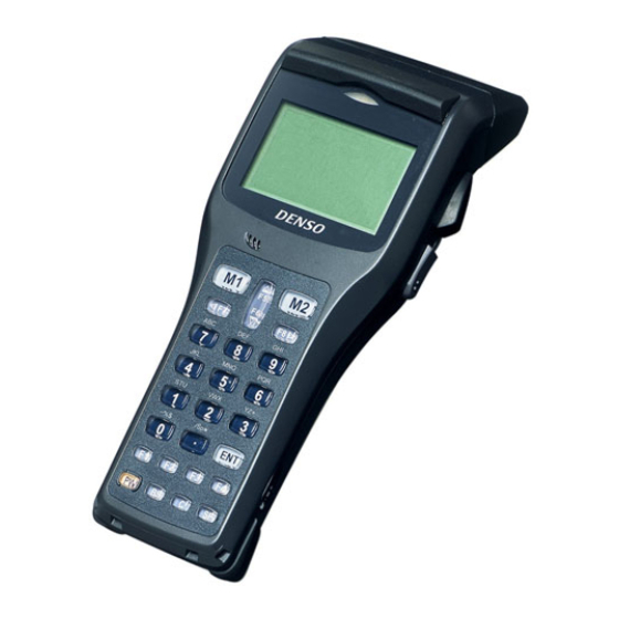
Page 28: Components And Functions
2.2 Components and Functions Liquid crystal display (LCD) Shows the characters and graphic patterns. Indication LED Illuminates in green when the BHT has successfully read a bar code. Trigger switch (M4 key) Press this switch to start bar-code reading. Trigger switch (M3 key) Press this switch to start bar-code reading. - Page 29 Chapter 2 Getting Started the BHT and System Mode The functions of the keys can be set by user programs. Shown below is a set of sample functions. Trigger switch Trigger switch (M3 key) (M4 key) Magic keys (M1 to M4) Each of the M3 and M4 keys is assigned a trigger switch by default.
-
Page 30: Preparation
2.3 Preparation 2.3.1 Setting-up 1: Loading the Battery Cartridge Before the first use of the BHT, be sure to load the battery cartridge as shown below. The battery cartridge is not loaded in the BHT when shipped from the factory. (1) Turn the BHT upside down. - Page 31 Chapter 2 Getting Started the BHT and System Mode • Avoid dropping the battery cartridge or letting it undergo any shock or impact. Doing so could cause the batteries to break, generate heat, rupture or burn. • Never charge the battery cartridge where any inflammable gases may be emitted;...
- Page 32 Low Battery Indication Low battery warning If the output voltage (of the battery cartridge) drops below a specified lower level while the BHT is in operation, the BHT displays the following warning message for approx. 2 seconds and beeps three times.
- Page 33 Chapter 2 Getting Started the BHT and System Mode • Before battery replacement, be sure to turn the BHT off. Within three minutes from the removal of the battery cartridge, load the battery cartridge to avoid data loss. After battery replacement, turn the BHT on and check its operation.
-
Page 34: Setting-Up 2: Setting The Calendar Clock
2.3.2 Setting-up 2: Setting the Calendar Clock Turn the BHT on by pressing the PW key. The following message appears. In the following cases, the above message appears. In such instances, it is necessary to set the date and time. (The indication "00/01/01 00:00" will differ depending upon the calendar clock state.) •... - Page 35 Chapter 2 Getting Started the BHT and System Mode (3) On the SET SYSTEM screen, press the 3 key to select the "DATE/TIME" and then press the ENT key. The screen shown at left will appear. (4) Use the numerical keys to enter the year (only the last two digits), month, day, hour, and minute in this order.
-
Page 36: Adjusting The Lcd Contrast & Beeper Volume And Switching The Beeper & Vibrator
2.3.3 Adjusting the LCD Contrast & Beeper Volume and Switching the Beeper & Vibrator While holding down the M1 or M4 key (right-hand trigger switch), press the PW key, and any of the following screens will appear on the LCD. This screen will disappear if you press the ENT key or no keys for five seconds. - Page 37 Chapter 2 Getting Started the BHT and System Mode Adjusting the LCD contrast You can adjust the LCD brightness to eight contrast levels. (1) Use the F5 and F6 keys to select the LCD CONTRAST line. (2) To decrease the contrast, press the F7 key; to increase it, press the F8 key. Switching the beeper &...
-
Page 38: Displaying The Battery Voltage Level And System Status
2.3.4 Displaying the Battery Voltage Level and System Status [ 1 ] Displaying the Battery Voltage Level On the SYSTEM MENU or during execution of user programs, pressing the ENT key while holding down the SF key will display the battery voltage level. As long as you hold down those keys, the following screen is displayed. - Page 39 Chapter 2 Getting Started the BHT and System Mode Shift state of the keys Pressing the SF key will shift the keys and show the icon in the right bottom corner of the LCD. Alphabet entry mode If the alphanumeric entry system has been selected in user programs, pressing the SF key will switch from the numeric entry mode to alphabet entry mode and show the icon Communications link with the CU-311 (in LAN-support software...
-
Page 40: Battery Replacement Notes
2.3.5 Battery Replacement Notes When is battery replacement needed? If the "Charge the battery!" appears on the LCD, replace the battery cartridge with a fully charged one. If you leave the BHT without replacing the battery cartridge, the integrated calendar clock or data will no longer be backed up so that the calendar clock will stop or the message "Contact your administrator. - Page 41 If the operation time of the fully recharged battery cartridge is noticeably shorter than normal, replace the battery cartridge with a new one. • Use only DENSO WAVE-authorized battery cartridges and chargers. • Never dispose of battery cartridges into a fire.
-
Page 42: Bht Turning-Off Notes
2.3.6 BHT Turning-off Notes [ 1 ] "Shutdown in progress" message When the BHT is turned off by pressing the PW key or by the auto power-off feature, it displays the following message and starts preparation for shutdown. When the above message is displayed, do not remove the battery cartridge. If you do so and leave the BHT without a battery cartridge loaded for one hour or more, then the error message "Contact your administrator. - Page 43 Chapter 2 Getting Started the BHT and System Mode (2) Press the 2 key while holding down the SF key again. The screen will switch to the following: [1] YES: Run Scandisk and start the System. [2] NO: Turn the BHT off. (3) Choose YES or NO with the numerical keys and press the ENT key.
-
Page 44: 3 ] About "$$Brklst.sys
Scandisk when the resume function is enabled If Scandisk runs when the resume function is enabled, the screen given below may appear. The screen may also appear when the calendar clock built in the BHT stops, even without running Scandisk. The BHT displays the screen for three seconds and then automatically runs the execution program from the beginning. -
Page 45: 4 ] If Invalid Files Are Found
Chapter 2 Getting Started the BHT and System Mode [ 4 ] If invalid files are found Even invalid files can be uploaded, so upload them to the host PC according to your needs. After uploading, - Delete those invalid files. (Refer to Section 2.5.3, "[ 8 ] Deleting Files.") - Download valid files having the same names as invalid ones. -
Page 46: Initializing The Bht System
2.4 Initializing the BHT System Initializing the system will lose program files and data files stored in the user area and make system settings revert to the factory defaults. You can delete font files by selecting the whole user area to be initialized. You need to initialize the system if: (1) You want to delete all of the program files and data files. - Page 47 Chapter 2 Getting Started the BHT and System Mode (1) Selecting the memory area to be initialized Press the PW key while holding down the SF, M1 and 0 keys together. The screen shown at left will appear. To initialize the user area except for the font file area, press the ENT key.
- Page 48 (3) Confirming the memory area selected for initialization Selecting the "USER AREA EXCEPT FONTS" in step (1) above will call up the confirmation screen shown at left. [1] Yes: Starts initialization. [2] No: Cancels initialization and turns the power off. Select a desired item by using the numerical keys, then press the ENT key.
- Page 49 Chapter 2 Getting Started the BHT and System Mode (5) Completion of initialization Upon completion of the initialization, the BHT displays the screen shown at left for a second and turns itself off automatically. • Do not turn the BHT off until the above initialization completion screen appears. A too-early turning-off will interrupt initialization, requiring you to initialize the BHT again.
-
Page 50: Operating In System Mode
2.5 Operating in System Mode System Mode is an operating software exclusively designed for the effective use of the BHT, which includes various functions as shown on the following pages. 2.5.1 Starting System Mode To start up System Mode, turn the BHT on while holding down the SF and 1 keys. This operation calls up the SYSTEM MENU on the LCD as shown below. - Page 51 Chapter 2 Getting Started the BHT and System Mode Structure of System Mode SYSTEM MENU ← Press the PW key while holding down the SF and 1 keys. Program Execution 1 and ENT Allows you to select a desired user keys program to be executed immediately.
- Page 52 Testing 5 and ENT Used for the bar-code reading test, keys memory test, beeper test, aging test, LCD indication test, indicator LED test, file test, communications test, key-entry test, vibrator test, and execution of PING (in LAN-support software only). (Refer to Section 2.5.3, [ 5 ].) System Information C key 6 and ENT...
- Page 53 Chapter 2 Getting Started the BHT and System Mode In addition to the functions given on the preceding pages, System Mode has these six functions: Deleting program/data files, Deleting font files, Downloading/uploading the BHT system parameter file, Setting the remote wakeup parameters, Downloading/uploading the system message file, and Updating the systems.
- Page 54 Downloading/uploading the system message file 6 with SF held down Downloads or uploads the system message file. (Refer to Section 2.5.3, [ 12 ].) C key Updating the Systems Period (.) with SF held Updates the BHT system and CU-311 down system (in LAN-support software...
-
Page 55: Operating In System Mode
Chapter 2 Getting Started the BHT and System Mode 2.5.2 Operating in System Mode Some functions in System Mode require several screens to be shifted, as shown in the example below. [ 1 ] Calling up the desired set screen First, select a desired item on the current screen by using the numerical key or the cursor keys (F5 and F6) so as to highlight the desired item. -
Page 56: 2 ] Selecting A Desired Setting
[ 2 ] Selecting a desired setting First, select a desired item on the current screen by using the numerical key or the cursor keys (F5 and F6) so as to highlight the desired item. Use the F7 and F8 keys to select a desired setting and then press the ENT key. The screen returns to the previous selection screen. -
Page 57: Detailed Description Of The Functions In System Mode
Chapter 2 Getting Started the BHT and System Mode 2.5.3 Detailed Description of the Functions in System Mode [ 1 ] Program Execution On the SYSTEM MENU, selecting "1:EXECUTE PROGRAM" calls up the screen shown at left. If more than one program has been downloaded to the user area of the target memory, use the F5 and F6 keys to move the cursor to a target program, and then press the ENT key. -
Page 58: 2 ] Downloading
[ 2 ] Downloading If you download a file having the same name as one already used in the user area of the target memory in the BHT, then the newly downloaded file replaces the old one. If no auto-start executable program has been specified (in Section 2.5.3, [4.1]), turning the BHT on lets... - Page 59 Chapter 2 Getting Started the BHT and System Mode Data that can be copied from one BHT to another BHT The copying function between BHTs copies the following set data: LCD contrast level Beeper volume Switching between beeper and vibrator Execution program to be run automatically when the BHT is turned on Message version (English or Japanese) Display font size...
- Page 60 BHT-5000 screen compatibility mode YMODEM option IP address of FTP server User name of FTP server Password of FTP server Default directory for FTP server FTP option, Line delimiters (CR/LF) FTP option, Treatment of line delimiters FTP option, Treatment of trailing spaces in data fields FTP option, Upload mode FTP option, Verbose mode IP address of host PC for ping...
- Page 61 Chapter 2 Getting Started the BHT and System Mode Download screens With this screen displayed, the BHT waits for a file to be downloaded. Selecting "2:HT<-->HT COPY" on the DOWNLOAD menu displays "HT<-->HT" in the center of the 2nd line; selecting "1:FILE" displays nothing on the 2nd line.
- Page 62 If an error occurs during downloading If some error occurs during downloading, the BHT beeps three times and shows one of the following screens with the prompt "Retry?": To retry the download, press the 1 and ENT keys; to abort it, press the 2 and ENT keys. Problem The memory is insufficient for storing files to be downloaded.
- Page 63 Chapter 2 Getting Started the BHT and System Mode Problem You attempted to download an invalid program file. Solution Check whether the program file you attempted to download is available to your BHT model. If it is not available, download the appropriate program.
-
Page 64: 3 ] Uploading
[ 3 ] Uploading On the SYSTEM MENU, selecting "3: UPLOAD" calls up the screen shown at left. [1] ONE FILE: Uploads a user program file or data file stored in the memory. [2] ALL FILES: Uploads all files in the memory except font files. - Page 65 Chapter 2 Getting Started the BHT and System Mode Upload screens If you select "1: ONE FILE" and choose a file to be uploaded or if you select the "2: ALL FILES" or "3:HT<-->HT COPY" on the UPLOAD menu, then the screen shown at left appears. Selecting "2: ALL FILES"...
- Page 66 If an error occurs during uploading If some error occurs during uploading, the BHT beeps three times and shows one of the following screens: To retry the uploading operation, press the 1 and ENT keys; to abort it, press the 2 and ENT keys. Problem The file you attempted to upload is damaged.
-
Page 67: 4 ] System Environment Setting
Chapter 2 Getting Started the BHT and System Mode [ 4 ] System Environment Setting On the SYSTEM MENU, selecting "4: SET SYSTEM" calls up the screen shown at left. [1] EXECUTE PROGRAM: Sets an auto-start execution program to be run when the power is turned on. [2] DISPLAY: Sets the message version (English or Japanese). - Page 68 [4.1] Setting an auto-start execution program On the SET SYSTEM menu, selecting "1: EXECUTE PROGRAM" calls up the screen shown at left. Highlighted is the current setting. Use the F5 and F6 keys to move the cursor to a desired execution program to be run automatically when the power is applied, and then press the ENT key.
- Page 69 Chapter 2 Getting Started the BHT and System Mode STATUS ( System Status Indication) Turning on the system status indication displays the following icons in the bottom line of the LCD: Indication Icon Description Shift state of the keys Appears when the keys on the keypad are shifted. Alphabet entry mode Appears when the BHT is placed in the alphabet entry mode.
- Page 70 [4.3] Setting the calendar clock On the SET SYSTEM menu, selecting "3: DATE/TIME" calls up the screen shown at left. Use the numerical keys to enter the year (only the last two digits), month, day, hour, and minute in this order, and then press the ENT key.
- Page 71 Chapter 2 Getting Started the BHT and System Mode [4.4] Setting the special bar-code scanning parameters On the SET SYSTEM menu, selecting "4: BARCODE" calls up the screen shown at left. Highlighted is the current setting. [1] INVERT: Activates or deactivates the black-and-white inverted label reading function.
- Page 72 MINIMUM DIGITS (Minimum number of digits to be read for ITF, STF, or Codabar) You can determine the minimum number of digits to be read for ITF, STF, and Codabar. Setting a small number of digits increases the frequency of digit-missing reading or misreading depending upon how to scan bar codes or the quality of bar codes.
- Page 73 Chapter 2 Getting Started the BHT and System Mode [4.5] Setting the communications environments After the BHT is initialized, the interface port and communications parameters are set as listed in the default table below. Do not access them unless necessary. Interface port Optical (IrDA interface port) YMODEM...
- Page 74 On the SET SYSTEM menu, selecting the "5: COMMUNICATION" calls up the screen shown at left. [1] OPTICAL: Switches to the communications parameters setting screen for the IrDA interface. [2] CONNECTOR: Switches to the communications parameters setting screen direct-connect interface. [3] COM PORT: Switches to the interface port setting screen.
- Page 75 Chapter 2 Getting Started the BHT and System Mode (1) Communications parameters setting screen On the SET OPTICAL screen, select "1: PARAMETER" to call up the screen shown at left. Highlighted is the current setting. Select the desired transmission speed by using the numerical keys or F7 and F8 keys, and then press the ENT key.
- Page 76 Setting the communications parameters for the direct-connect interface On the SET COMMUNICATION menu, select "2: CONNECTOR" to call up the screen shown at left. [1] PARAMETER: Switches to the communications parameters setting screen. [2] PROTOCOL: Switches to the communications protocol screen. Select a desired screen by using the numerical keys or F5 and F6 keys, and then press the ENT key.
- Page 77 Chapter 2 Getting Started the BHT and System Mode (2) Communications protocol option menu On the SET CONNECTOR screen, select "2: PROTOCOL" to call up the screen shown at left. Highlighted is the current setting. [1] SERIAL No.: Selects whether or not to add serial numbers to data blocks.
- Page 78 Setting the interface port On the SET COMMUNICATION menu, select the "3: COM PORT" to call up the screen shown at left. Highlighted is the current setting. [1] BASIC: Selects the IrDA (Optical) or direct-connect (Connector) interface port to be used for user programs written in BHT-BASIC (OPEN "COM:").
- Page 79 Chapter 2 Getting Started the BHT and System Mode Setting the communications protocol type On the SET COMMUNICATION menu, select "4: PROTOCOL TYPE" to call up the screen shown at left. Highlighted is the current setting. [1] Ymodem: Selects Ymodem for file transfer in System Mode or for the execution of XFILE statement in BHT-BASIC.
- Page 80 On the PROTOCOL TYPE screen, select the "3: BHT-Ir Protocol" to call up the screen shown at left. Enter the ID number of the BHT by using the numerical keys, and then press the ENT key. If you do not need to modify the current setting, press the ENT key only.
- Page 81 Chapter 2 Getting Started the BHT and System Mode [4.6] Defining the functions of the shift key and magic keys On the SET SYSTEM menu, selecting the "6: KEY" calls up the screen shown at left. Highlighted is the current setting. [1] SHIFT KEY: Switches to the SF key definition screen.
- Page 82 Defining the function of M1 , M2 , M3 (left-hand trigger switch), or M4 (right-hand trigger switch) On the SET KEY menu, select "2: M1 KEY," "3: M2 KEY," "4: M3 KEY" or "5: M4 KEY" to call up the screen as shown at left. (This example appears when the "4: M3 KEY"...
- Page 83 Chapter 2 Getting Started the BHT and System Mode [4.7] Setting the resume function On the SET SYSTEM menu, selecting "7: RESUME" calls up the screen shown at left. Highlighted is the current setting. [1] ON: Activates the resume function that resumes the current BHT status (screen) where the BHT was turned off, when the BHT is turned on.
- Page 84 [4.9] Setting the TCP/IP, FTP and DHCP (in LAN-support software only) On the SET SYSTEM menu, selecting "9: TCP/IP" calls up the screen shown at left. [1] SET TCP/IP: Switches to the TCP/IP setting screen. [2] SET FTP: Switches to the FTP setting screen. [3] SET DHCP: Switches to the DHCP setting screen.
- Page 85 Chapter 2 Getting Started the BHT and System Mode (2) IP address screen On the SET TCP/IP screen, select "2: IP ADDRESS" to call up the screen shown at left where the current settings are displayed. Select a desired item by using the numerical keys or F5 and F6 keys, and then press the ENT key.
- Page 86 [4.9-2] Setting the FTP On the SET TCP/IP, FTP and DHCP menu, select "2: SET FTP" calls up the screen shown at left. [1] SERVER: Switches to the FTP server connection environments screen. [2] OPTION: Switches to the data transfer parameters screen. Select a desired item by using the numerical keys or F5 and F6 keys, and then press the ENT key.
- Page 87 Chapter 2 Getting Started the BHT and System Mode (2) FTP options screen On the SET FTP menu, select "2: OPTION" to call up the screen shown at left where the current settings are displayed. [1] CR/LF: Specifies line delimiters that should match ones used in the server OS.
- Page 88 [4.9-3] Setting the DHCP On the SET TCP/IP, FTP and DHCP menu, selecting "3: DHCP" calls up the screen shown at left. The current setting is displayed. [1] TIMEOUT: Sets the timeout for getting the IP configuration from the DHCP server. The entry range is from 00001 to 32767 seconds.
-
Page 89: 5 ] Testing
Chapter 2 Getting Started the BHT and System Mode [ 5 ] Testing On the SYSTEM MENU, selecting "5: TEST" calls up the screen shown at left. [1] BARCODE: Selects the bar-code reading test. [2] MEMORY: Selects the RAM read/write test. [3] BEEPER: Selects the beeper scale test. - Page 90 [5.1] Bar-code reading test On the TEST menu, selecting "1: BARCODE" calls up the screen shown at left. Actually read bar codes with the BHT and check the read data displayed on the LCD. ⇓ Bar-code type Number of digits of the bar code Upon completion of bar-code reading, the BHT beeps, turns on the indicator LED in green, and displays the read data together with the barcode type and the number of digits.
- Page 91 Chapter 2 Getting Started the BHT and System Mode [5.2] Memory test On the TEST menu, selecting "2: MEMORY" calls up the screen shown at left and starts writing and reading onto/from all areas of the RAM as well as checking the address. XXXXX: Tested RAM capacity (unit: kilobytes) YYYYY: Total RAM capacity (unit: kilobytes) If any error is detected, the BHT beeps three times, shows the...
- Page 92 [5.3] Beeper scale test On the TEST menu, selecting "3: BEEPER" calls up the screen shown at left and makes the beeper sound at three octaves listed below. Upon completion of this test, the BHT automatically returns to the TEST menu. To stop this test while in progress, turn the BHT off.
- Page 93 Chapter 2 Getting Started the BHT and System Mode [5.5] LCD and indicator LED tests On the TEST menu, selecting "5: LCD" calls up the test pattern shown at left on the LCD. The indicator LED is off. Each time the ENT key is pressed, the screen shifts to the next test pattern.
- Page 94 [5.6] File test On the TEST menu, selecting "6: FILE" calls up the screen shown at left. Memory space being used XXXXXX: Free memory space YYYYYY: If any of the files stored in the memory is defective, an asterisk (*) or plus sign (+) is prefixed to the name of the defective file (s).
- Page 95 Chapter 2 Getting Started the BHT and System Mode [5.7] Communications test In System Mode, you can test the IrDA interface port and direct-connect interface port. Preparation for the IrDA interface test Arrange two BHTs, one as a master station and the other as a slave station (to be tested) with their IrDA interface ports facing each other as illustrated below.
- Page 96 Testing the IrDA interface port On the TEST COMMUNICATION menu, selecting "1: OPTICAL" calls up the screen shown at left. At the slave BHT to be tested, select the "1: SLAVE" and at the master BHT, select the "2: MASTER." Then press the ENT key. During the test, the screen shown at left is displayed.
- Page 97 Chapter 2 Getting Started the BHT and System Mode Testing the direct-connect interface port On the TEST COMMUNICATION menu, selecting "2: CONNECTOR" displays the screen shown at left and then starts testing the direct-connect interface port. If any error occurs, the BHT beeps three times and shows the screen at left.
- Page 98 [5.8] Key-entry, beeper and vibrator test On the TEST menu, selecting "8: KEY & VIBRATION" calls up the screen shown at left and makes the BHT ready for entry from the keypad. Pressing individual keys displays the identifier letters in the positions pre-assigned to those keys on the LCD as well as sounding the beeper or running the vibrator.
- Page 99 Chapter 2 Getting Started the BHT and System Mode Testing with PING [5.9] (in LAN-support software only) On the TEST menu, selecting "9: PING" calls up the screen shown at left. [1] RUN PING: Runs PING. [2] SET PING: Switches to the PING parameter setting screen. [3] SET DEVICE: Switches to the PING device setting screen.
- Page 100 PING run-time messages (that will appear in the middle of the LCD) Message Displays when: Waiting Setting up PING. Opening TCP/IP Opening devices. Routing TCP/IP Connecting to the TCP/IP communications pathway. PING start Starting PING. Device error Failed to open a device. TCP/IP error Failed to connect to the TCP/IP communications pathway.
- Page 101 Chapter 2 Getting Started the BHT and System Mode If you select one of "1: DESTINATION IP" through "5: COUNT" items and press the ENT key, then the entry box of that item becomes ready to accept entry and a cursor appears. Enter the desired value by using the numerical keys and period (.) key, and then press the ENT key.
- Page 102 PING Echo Request Send Timing (SEND TYPE) Two types of echo request send timings are available: TYPE 1 and TYPE 2. TYPE 1 After sending an echo request, PING waits for the period specified by INTERVAL and then sends echo request again. For TYPE 1, the relationship between the INTERVAL and TIMEOUT should be "INTERVAL ≥...
- Page 103 Chapter 2 Getting Started the BHT and System Mode (3) PING device screen On the TEST PING menu, select "3: SET DEVICE" to call up the screen shown at left where the current TCP/IP device, link layer, and transmission speed are displayed. To return to the TEST PING menu, press the C key when any item is highlighted.
-
Page 104: 6 ] System Information
[ 6 ] System Information [6.1] Displaying the BHT system information On the SYSTEM MENU, selecting the "6: VERSION" calls up the screen shown at left, displaying the system program version, ROM and RAM sizes, system message version, and font types and their versions. - Page 105 Chapter 2 Getting Started the BHT and System Mode If the M2 key is pressed when the BHT is not placed on the CU-311 The error message shown at left will appear. Press the C key to return to the SYSTEM INFORMATION screen.
-
Page 106: 7 ] Downloading/Uploading By Ftp (In Lan-Support Software Only)
[ 7 ] Downloading/Uploading by FTP (in LAN-support software only) On the SYSTEM MENU, selecting "7: FTP" calls up the screen shown at left. [1] DOWNLOAD: Downloads a file by FTP. [2] UPLOAD: Uploads a file(s) by FTP. Select a desired item by using the numerical keys or F5 and F6 keys, and then press the ENT key. - Page 107 Chapter 2 Getting Started the BHT and System Mode DIR/FILE entry box: The FTP client will interpret a character string entered into this box as a directory name at first, so it will send a Change Directory request to the FTP server. If the specified directory exists in the FTP server, the server will change a directory from the default to that specified one;...
- Page 108 If you select "2: SELECT FILE," the screen shown at left will appear. Choose a file to be uploaded by using the F5 and F6 keys, then press the ENT key. The screen returns to the previous one where the selected file appears in the SELECT FILE entry box.
- Page 109 Chapter 2 Getting Started the BHT and System Mode Run-time messages in downloading/uploading by FTP When the BHT is uploading or downloading files by FTP, the following messages will appear in the bottom of the LCD: Message Displays when: Aborted. Uploading or downloading is interrupted.
- Page 110 Reply codes from the FTP server The messages that FTP servers send during and after FTP operations vary, but servers all use the same reply codes as listed below. Reply codes Description Restart marker reply. Service ready in nnn minutes. Data connection already open;...
-
Page 111: 8 ] Deleting Program/Data Files
Chapter 2 Getting Started the BHT and System Mode [ 8 ] Deleting Program/Data Files You may delete a program file or data file stored in the flash ROM. On the SYSTEM MENU, pressing the 0 key with the SF key held down calls up the screen shown at left. -
Page 112: 9 ] Deleting Font Files
[ 9 ] Deleting Font Files You may delete font files stored in the flash ROM if you do not need to display Japanese fonts (16-dot and/or 12-dot fonts) and the user area is insufficient. Deleting those font files allows the memory area which was occupied by those files to be used as a user area. -
Page 113: 10 ] Downloading/Uploading The Bht System Parameter File
Chapter 2 Getting Started the BHT and System Mode [ 10 ] Downloading/Uploading the BHT System Parameter File The BHT system parameter file (named "_BHT.SYS") stores system environment settings specified in the SET SYSTEM menu (in Section 2.5.3, [ 4 ]) and other settings such as the LCD contrast and beeper volume. - Page 114 [10.1] Downloading the BHT system parameter file Selecting "1: DOWNLOAD" on the SYSTEM PARAMETER transfer menu calls up the screen shown at left. With this screen displayed, the BHT waits for the BHT system parameter file to be downloaded. ⇓ While the downloading operation is in progress, the screen shown at left is displayed indicating the file name and the number of received records/the total number of records.
- Page 115 Chapter 2 Getting Started the BHT and System Mode If an error occurs during downloading If some error occurs during downloading, the BHT beeps three times and shows one of the following screens with the prompt "Retry?": To retry the download, press the 1 and ENT keys; to abort it, press the 2 and ENT keys. To return to the SYSTEM PARAMETER transfer menu, press the C key.
- Page 116 [10.2] Uploading the BHT system parameter file Selecting "2: UPLOAD" on the SYSTEM PARAMETER transfer menu calls up the screen shown at left. With this screen displayed, the BHT waits for the BHT system parameter file to be uploaded. ⇓ While the uploading operation is in progress, the screen shown at left is displayed indicating the file name and the number of sent records/the total number of records.
- Page 117 Chapter 2 Getting Started the BHT and System Mode If an error occurs during uploading If some error occurs during uploading, the BHT beeps three times and shows one of the following screens: To retry the uploading operation, press the 1 and ENT keys; to abort it, press the 2 and ENT keys. Press the C key to return to the SYSTEM PARAMETER transfer menu.
-
Page 118: 11 ] Setting The Remote Wakeup
[ 11 ] Setting the Remote Wakeup On the SYSTEM MENU, pressing the 4 key with the SF key held down calls up the screen shown at left. [1] REMOTE WAKEUP: Activates or deactivates the remote wakeup function. [2] TRANSMIT SPEED: Sets the transmission speed for the remote wakeup. -
Page 119: 12 ] Downloading/Uploading The System Message File
Chapter 2 Getting Started the BHT and System Mode [ 12 ] Downloading/Uploading the System Message File The system message file (named "_B30MSG.FN3") stores system messages, e.g., "Shutdown in progress. Do not remove the battery." and "Charge the battery!." The SYSTEM MESSAGE transfer menu allows you to upload or download the system message file to/from the host PC. - Page 120 [12.1] Downloading the system message file Selecting "1: DOWNLOAD" on the SYSTEM MESSAGE menu calls up the screen shown at left. With this screen displayed, the BHT waits for the system message file to be downloaded. ⇓ While the downloading operation is in progress, the screen shown at left is displayed indicating the file name and the number of received records/the total number of records.
- Page 121 Chapter 2 Getting Started the BHT and System Mode If an error occurs during downloading If some error occurs during downloading, the BHT beeps three times and shows one of the following screens with the prompt "Retry?": To retry the download, press the 1 and ENT keys; to abort it, press the 2 and ENT keys. To return to the SYSTEM MESSAGE transfer menu, press the C key.
- Page 122 [12.2] Uploading the system message file Selecting "2: UPLOAD" on the SYSTEM MESSAGE transfer menu calls up the screen shown at left. With this screen displayed, the BHT waits for the system message file to be uploaded. ⇓ While the uploading operation is in progress, the screen shown at left is displayed indicating the file name and the number of sent records/the total number of records.
- Page 123 Chapter 2 Getting Started the BHT and System Mode If an error occurs during uploading If some error occurs during uploading, the BHT beeps three times and shows one of the following screens: To retry the uploading operation, press the 1 and ENT keys; to abort it, press the 2 and ENT keys. Press the C key to return to the SYSTEM MESSAGE transfer menu.
-
Page 124: 13 ] Updating The Systems
[ 13 ] Updating the Systems On the SYSTEM MENU, pressing the period (.) key with the SF key held down calls up the screen shown at left. [1] SYSTEM MODIFY: Switches to the BHT system updating menu. [2] CU-F/W MODIFY: Switches to the CU-311 system updating menu (in LAN-support software... - Page 125 Chapter 2 Getting Started the BHT and System Mode If the displayed filename is different from the name of the BHT system reconfig file you want to use, then select "2: FILENAME" and enter the correct filename. Selecting "2: FILENAME" makes the entry box ready to accept entry and displays a cursor.
- Page 126 [13.2] Updating the CU-311 System via the BHT (in LAN-support software only) Before proceeding to the updating procedure, you need to download a CU-311 system reconfig file, referring to Section 2.6.2. On the MODIFY MENU screen (that can be called up by pressing the period (.) key with the SF key held down on the SYSTEM MENU), selecting "2: CU-F/W MODIFY"...
- Page 127 Chapter 2 Getting Started the BHT and System Mode If no CU-311 system reconfig file exists at the start of updating If no system file exists in the BHT when you select "1: DO IT," then the message shown at left will appear. Download a CU-311 system reconfig file to the BHT and then try updating again.
-
Page 128: Downloading System Reconfig Files And Updating The Current Systems
During system updating, the PW key is disabled so that the BHT cannot be turned off. Wait for completion of updating and then press the PW key. The latest BHT system reconfig file can be downloaded from our Web site. http://www.denso-wave.com/... -
Page 129: Updating The Cu-311 System (In Lan-Support Software Only)
If the CU-311 has been turned off during updating, restarting it will run either the old CU-311 system or updated one. You may check which system is running on the CU INFORMATION screen given in Section 2.5.3, [ 6 ]. The latest CU-311 system reconfig file can be downloaded from our Web site. http://www.denso-wave.com/... -
Page 130: Starting Up User Programs
2.7 Starting Up User Programs You may start up user programs (application programs) in the BHT in several ways. This section outlines those ways. Starting from the EXECUTE PROGRAM menu in System Mode If you select a desired user program as an execution program in the EXECUTE PROGRAM menu, then the selected program will immediately start running. - Page 131 Chapter 2 Getting Started the BHT and System Mode Example 1: Downloading updated versions of the MAIN.PD4 and SUBMAIN.PD4 In this case, the registration order of user programs will not change, so pressing the PW key will start the MAIN.PD4. •...
- Page 132 Starting with the wakeup function If you specify the wakeup time in user programs, the wakeup function will automatically wake up the BHT at the specified time and run a user program. If an auto-start execution program has been selected on the SET EXECUTE PROGRAM screen in the SET SYSTEM menu, the selected program will run at the time of wakeup.
- Page 133 Communications Operations of BHT This chapter outlines the BHT’s communications capabilities necessary for performing data and program transfer between the BHT-300B and host PC or other devices: infrared (Ir) communication, RS-232C interface specifications, and the basic communications specifications. Infrared Communication ...........................120 RS-232C Interface Specifications ........................122...
-
Page 134: Infrared Communication
3.1 Infrared Communication The BHT has an integrated infrared communications unit which enables wireless transfer of programs and data between a BHT and a host PC and between two BHTs. The IR communications device features the following: • Wireless communications •... - Page 135 Chapter 3 Communications Operations of BHT The BHT's IR communications device is IrDA-compliant. IrDA stands for Infrared Data Association, which has defined hardware (IrDA Serial Infrared Physical Layer Link) and communications protocols for IR communications. The BHT's physical layer complies with the IrDA1.2 Low Power, with a maximum transfer distance of 0.15 m and maximum transmission rate of 115.2 kbits per second.
-
Page 136: Rs-232C Interface Specifications
3.2 RS-232C Interface Specifications [ 1 ] Interface Connector and Pin Assignment The BHT has a direct-connect interface port which is connectable to the 3-pole mini stereo plug (φ2.5 mm or 0.1") and supports a subset of the RS-232C interface as shown below. Using a direct-connect interface cable having the mini stereo plugs makes it possible to connect the BHT to a host PC (or another BHT) directly without any routing through the CU-300. -
Page 137: 2 ] Interface Cable Connection
Chapter 3 Communications Operations of BHT [ 2 ] Interface Cable Connection Connect the BHT directly to a host PC, a modem, or a printer with a direct-connect interface cable as illustrated below. Cable Connection between BHT and Host PC Cable Connection between BHT and Modem Cable Connection between BHT and Printer... -
Page 138: Basic Communications Specifications And Parameters
Basic Communications Specifications and Parameters 3.3.1 Basic Communications Specifications Listed below are the communications specifications when the BHT exchanges data with a host PC through the IrDA interface or direct-connect interface. IrDA Interface Direct-connect Interface Synchronization Start-stop Transmission Speed 2400, 9600, 19200, 38400, 300, 600, 1200, 2400, 4800, 9600, 57600, or 115200 bps 19200, 38400, 57600, or 115200 bps... - Page 139 Chapter 3 Communications Operations of BHT Transmission Code and Bit Order All characters should be coded to 7- or 8-bit code for data transmission. The standard data exchange code of the BHT is JIS 7- or 8-bit code. The transmission bit order is LSB (Least significant bit) first. What follows is an example for transmitting character A (41h, 01000001b) coded to JIS 8-level code with an even parity and a single bit each for start and stop bits.
-
Page 140: Communications Parameters
3.3.2 Communications Parameters In System Mode and user programs written in BHT-BASIC, you can set the communications parameters listed below. Communications Port IrDA interface Direct-connect interface Transmission Speed 2400, 9600, 19200, 38400, 300, 600, 1200, 2400, 4800, 9600, 57600, or 115200 bps 9200, 38400, 57600, or 115200 bps Character Length 8 bits... -
Page 141: Error Messages
Chapter 4 Error Messages This chapter lists the error messages which will appear on the LCD if some error occurs in the BHT. System Errors................................128 Errors in System Mode..............................135... -
Page 142: System Errors
4.1 System Errors If some error occurs when the power is turned on or during program execution, one of the following error messages will appear on the LCD. System Program error Problem A System Program error has occurred. If this error occurs, the BHT beeps five times (for 0.1 second per beep) and then turns itself off. - Page 143 Chapter 4 Error Messages Shutdown due to low battery Problem When the BHT is switched on or being on (including during execution of a program), the battery output level has lowered so that the BHT no longer operates. If lower battery is detected, the BHT beeps five times (for 0.1 second per beep) and then turns itself off.
- Page 144 Abnormal shutdown Problem The BHT was shut down abnormally* and has been left without a battery cartridge loaded or with a discharged battery cartridge loaded, so unsaved data is lost. (*"Normally shut down" refers to "the BHT is turned off with the PW key or by the auto power-off feature.") Solution Refer to Chapter 2, Section 2.3.6 "BHT Turning-off Notes."...
- Page 145 Chapter 4 Error Messages System Program malfunction Problem During execution of System Program, the System Program has attempted to write onto the write-protected area of the memory. (xxxxxxxx: Error address) If this error occurs, the BHT beeps five times (for 0.1 second per beep).
- Page 146 No user programs found Problem When the BHT is turned on, no user programs are found. Solution You can run the code scanning demo without user programs. Pressing "1:Yes" runs the code scanning demo. To start the demo, press the trigger switch. Selecting "2:No" turns the power off. Resume data lost Problem Although the resume function had been set to ON, no resume data...
- Page 147 Chapter 4 Error Messages Error in System Mode settings Problem Your settings made in System Mode contain an error. If this error occurs, the System Mode settings revert to the factory defaults. The BHT displays this error for three seconds and runs a user program first loaded in the BHT from the beginning.
- Page 148 System administrator to be called Problem Any of the following errors has occurred: (1) Hardware error or calendar clock error (1010) Flash memory error (1020) (2) Memory storage error (20XX) (3) Execution program error (3010) (XXXX: Error code) If any of the above errors occurs, the BHT beeps five times (for 0.1 second per beep) and then turns itself off.
-
Page 149: Errors In System Mode
Chapter 4 Error Messages 4.2 Errors in System Mode If some error occurs during operation in System Mode, one of the following error messages will appear on the LCD. When selecting a program file or data file Problem You attempted to execute a user program in the EXECUTE PROGRAM menu, but no user program files had been stored in the memory. - Page 150 Problem You have deleted all of the files stored in the memory in the DELETE FILE menu. Solution Press the C key to return to the SYSTEM MENU screen. During downloading of a program file, data file, BHT system parameter file, or system message file Problem The memory is insufficient for storing files to be downloaded.
- Page 151 Chapter 4 Error Messages Problem The current download will exceed the maximum allowable number of files (120 files) in the memory. Solution Press the 2 key to return to the SYSTEM MENU, then delete unnecessary files in the memory (or decrease the number of files to be downloaded if you attempted to download more than one file in the DOWNLOAD menu.) (Refer to Chapter 2, Section 2.5.3, [ 8 ], [ 2 ], [ 10 ], and [ 12 ].)
- Page 152 During uploading of a program file, data file, BHT system parameter file, or system message file Problem The file you attempted to upload is damaged. Solution To upload the damaged file as is, press the 1 key. Problem The memory is insufficient for setting up the BHT system parameter file or system message file to be uploaded.
- Page 153 This chapter describes the handling procedure of the communication unit CU-300, the interfacing with the host PC, and the charging of the battery cartridge. It also describes the LAN-support communication unit CU-311. Functions of the CU-300 ..........................140 Components and Functions ..........................141 Applying Power to the CU-300........................142 Communicating with the Host PC ........................144 5.4.1 Setting the Transmission Speed of the CU-300 ..................144...
-
Page 154: Functions Of The Cu-300
5.1 Functions of the CU-300 The optical communication unit CU-300 series is available in three models: CU-301, CU-321 and CU-311. The CU-300 series has the following functions: (1) Data exchange function The CU-300 exchanges data and programs between the BHT and the host PC. It interfaces with the BHT via the IrDA interface and with the host PC via the RS-232C interface (CU-301), USB interface (CU-321) or Ethernet 10Base-T interface (CU-311). -
Page 155: Components And Functions
Chapter 5 Handling the CU-300 (Option) 5.2 Components and Functions Indicator LED Shows the charging state. IrDA interface port Used to exchange data optically with the BHT. BHT charge terminals Do not stain these terminals; doing so could result in a lower charging efficiency. -
Page 156: Applying Power To The Cu-300
5.3 Applying Power to the CU-300 CU-301: The CU-301 should be powered from a wall socket via the dedicated AC adapter. Connect the outlet plug of the AC adapter to the power inlet connector of the CU-301, then plug the other end into a wall socket. - Page 157 Chapter 5 Handling the CU-300 (Option) • If smoke, abnormal odors or noises come from the CU, immediately unplug the AC adapter from the wall socket, disconnect the interface cable from the CU, and contact your nearest dealer. Failure to do so could cause fire or electrical shock. •...
-
Page 158: Communicating With The Host Pc
Communicating with the Host PC 5.4.1 Setting the Transmission Speed of the CU-300 CU-301: Set the transmission speed to the same value as that of the BHT and host PC, by using the DIP switch. CU-321: The transmission speed is automatically determined by the host PC. CU-311: Use the CU with the transmission speed fixed to 115,200 bps (default). -
Page 159: Interface Cable Connection
Chapter 5 Handling the CU-300 (Option) 5.4.2 Interface Cable Connection (1) CU-301/321: Unplug the AC adapter (if connected) from the wall socket. (2) Make sure that the host PC is turned off. (3) CU-301: Connect the RS-232C interface cable to the interface port of the CU-301. CU-321: Connect the USB interface cable to the interface port of the CU-321. -
Page 160: Interfacing With The Host Pc
5.4.3 Interfacing with the Host PC [ 1 ] CU-301/321 This section describes how to start communication with the host PC in System Mode. The same can apply when you use a user program. (1) Turn the host PC on. (2) CU-301: Turn the power switch on. -
Page 161: 2 ] Cu-311
Chapter 5 Handling the CU-300 (Option) [ 2 ] CU-311 This section describes how to start communication with the host PC in System Mode (FTP). (1) Turn the host PC on. (2) Make sure that the AC adapter is plugged into a wall socket and the POWER LED is lit. (3) Turn the BHT off and then put it on the CU-311. -
Page 162: Charging The Battery Cartridge
5.5 Charging the Battery Cartridge You can charge a rechargeable battery cartridge being loaded in the BHT. Service Life of Rechargeable Battery Cartridge: Lithium-ion batteries used in the rechargeable battery cartridge will gradually deteriorate during the repeated cycles of charging and discharging due to its properties, even under normal use. When the battery service period becomes shortened due to its deterioration even if it has been charged for the specified hours, replace the battery cartridge with a new one. - Page 163 Chapter 5 Handling the CU-300 (Option) Charging Operation and LED Indication Operator's Action CU-300 Status Indicator LED on the BHT On standby ⇓ Place the BHT on the CU-300. Normal charging ON (in red) ⇓ ⇓ After approx. 3 hours Charging completed ON (in green) (approx.
-
Page 164: Functions Exclusive To The Cu-311
Functions Exclusive to the CU-311 5.6.1 Displaying the CU-311 Status You can check the machine status of the CU-311 according to the ON/OFF states of the LED indicators (POWER and DATA) as listed below. For the charging procedure, refer to Chapter 5, Section 5.5, "Charging the Battery Cartridge."... -
Page 165: Displaying The Cu System Information On The Bht
Chapter 5 Handling the CU-300 (Option) 5.6.2 Displaying the CU System Information on the BHT You can display the CU-311 system information on the BHT's LCD. Set the BHT on the CU-311 and operate the BHT to display the SYSTEM INFORMATION screen on the LCD. -
Page 166: Interface Specifications
5.7 Interface Specifications [ 1 ] Interface Connector and Pin Assignment CU-301 The CU-301 has an RS-232C interface port (Dsub-9P). RS-232C Interface Port (Dsub-9P) on the CU-301 Signal Input/Output Pin No. Signal Functions CU-301 External device ← Receive data → Send data →... - Page 167 Chapter 5 Handling the CU-300 (Option) CU-311 The CU-311 has an IEEE802.3-compliant Ethernet interface port (10Base-T). Ethernet Interface Port (RJ45 jack) on the CU-311 Pin No. Signal Functions Send data Send data Receive data N.C. No connection N.C. No connection Receive data N.C.
-
Page 168: 2 ] Interface Cable Connection
[ 2 ] Interface Cable Connection CU-301 As illustrated below, connect the CU-301 (on which the BHT is placed) to a host PC with a cross-mode cable. To connect it to a modem, use a straight-mode cable. CU-301 Host PC (DTE) (DTE) Cable Connection between CU-301 and Host PC... - Page 169 Appendix A. Specifications ..............................156 BHT-300B.................................156 [ 1 ] Product Specifications ..........................156 [ 2 ] Bar Code Specifications ..........................157 [ 3 ] Interface Specifications..........................159 CU-300 ................................160 [ 1 ] Product Specifications ..........................160 [ 2 ] Charging/Discharging Requirements (CU-301/321/311) ................160 [ 3 ] Interface Specifications..........................161...
- Page 170 Appendix A. Specifications A.1 BHT-300B [ 1 ] Product Specifications Power Source Main power Rechargeable lithium-ion battery cartridge (3.7 VDC) Dimensions (W) x (L) x (H) 70 x 182 x 55 mm (2.8 x 7.2 x 2.2 inches) Weight Approx. 230 g (Approx. 8.19 oz.) including battery cartridge Operating Ambient Temperature -5°C to 50°C (23°F to 122°F)
- Page 171 Appendices [ 2 ] Bar Code Specifications (1) Available Bar Code Types Bar code type Bar dimensions Readable magnification Universal product codes EAN-13 EAN-8 UPC-A UPC-E EAN-13 with add-on 0.26 mm (10.24 mils) 0.8 magnification min. EAN-8 with add-on UPC-A with add-on UPC-E with add-on 2-digit add-on 5-digit add-on...
- Page 172 (3) Bar Code Label Size Recommended width: 10 mm min. (0.39 inch min.) Length: Depth of field Length of labels (including margins) (Distance from bar codes to the bar-code reading window) 400 mm (15.75 inches) 420 mm max. (16.54 inches max.) (Minimum narrow bar width: 1.0 mm min.)* (4) Thickness of Bars and Depth of Field Minimum narrow bar width...
- Page 173 Appendices [ 3 ] Interface Specifications IrDA Interface Synchronization: Start-stop Input signals: Output signals: Transmission speed: 115,200 bps max. Direct-connect Interface Synchronization: Start-stop Transmission speed: 115,200 bps max. Signal level: Conforms to the RS-232C interface Pin assignment: As shown below. Signal Input/Output Pin No.
- Page 174 A.2 CU-300 [ 1 ] Product Specifications CU-301 CU-321 CU-311 Power Source 100, 120 or 230 VAC 100, 120 or 230 VAC Powered from the USB (via the dedicated AC (via the dedicated AC interface* adapter) adapter) Power 6.5 VA 5V 500 mA 7 VA Consumption...
- Page 175 Appendices [ 3 ] Interface Specifications CU-301 RS-232C Interface Port (Dsub-9P) on the CU-301 Signal Input/Output Pin No. Signal Functions CU-301 External device ← Receive data → Send data → Data terminal equipment ready Signal ground • \ Data set ready •...
- Page 176 CU-321 The CU-321 has a Full-Speed USB 1.1-capable port (Series "B" receptacle). CU-311 The CU-311 has an IEEE802.3-compliant Ethernet interface port (10Base-T). Ethernet Interface Port (RJ45 jack) on the CU-311 Pin No. Signal Functions Send data Send data Receive data N.C.
- Page 177 Appendices Appendix B. A Typical Basic Operation What follows is a typical basic operation that helps you instruct the hands-on user in practical bar-code reading operation. Application type: Inventory → → Operation: Power ON Read the bar code on stock (A). Key in the quantity.
- Page 178 BHT-300B. Please feel free to send your comments regarding any errors or omissions you may have found, or any suggestions you may have for generally improving the manual. In no event will DENSO WAVE be liable for any direct or indirect damages resulting from the application of the information in this manual.
Need help?
Do you have a question about the BHT-300B and is the answer not in the manual?
Questions and answers