Simplex 4100U Application Manual
Smoke management
Hide thumbs
Also See for 4100U:
- Installation & maintenance (180 pages) ,
- Operator's manual (76 pages) ,
- Wiring diagrams (34 pages)
Table of Contents
Advertisement
Quick Links
Advertisement
Table of Contents

Related Manuals for Simplex 4100U


Summary of Contents for Simplex 4100U
- Page 1 Smoke Management Application Guide 574-465 Rev. D...
- Page 3 Acknowledgements Acknowledgements Tyco Safety Products – Westminster, gratefully acknowledges the contributions of the following organizations to this publication: • American Society of Heating, Refrigerating and Air-Conditioning Engineers, Inc. (ASHRAE), Atlanta, GA. • Andover Controls Corporation, Andover, MA. • Center for Fire Research, National Engineering Laboratory, National Bureau of Standards, U.S.
- Page 4 ELECTRICAL HAZARD - Disconnect electrical field power when making any internal adjustments or repairs. All repairs should be performed by a representative or authorized agent of ® your local Simplex product supplier. STATIC HAZARD - Static electricity can damage components. Therefore, handle as follows: 1.
- Page 5 We retain the rights of our respective trademarks. Trademarks Simplex, the Simplex logo, TrueSite, TrueAlarm, and IDNet are either trademarks or registered trademarks of Tyco International Ltd and its affiliates and are used under license. NFPA 72 and National Fire Alarm Code are registered trademarks of the National Fire Protection Association (NFPA).
-
Page 7: Table Of Contents
Table of Contents Chapter 1 How Smoke Control Systems Work Purpose ........................1-1 Introduction ......................1-1 In this Chapter ......................1-1 Introduction ........................1-2 Design Parameters ....................1-2 Design Concepts ..................... 1-2 Controlling Smoke Movement ..................1-3 Basic Concept ......................1-3 Creating Smoke Zones .................... - Page 8 In this Chapter ......................4-1 General Smoke Control Interconnections ..............4-2 Overview ........................4-2 UUKL Addressable Monitor/Control Devices for 4100U/4100ES ......4-3 Reference Information ..................... 4-4 Four Story Building Smoke Control Example ............4-5 Dedicated Smoke Control System Wiring ..............4-6 Overview ........................
- Page 9 Chapter 5 Smoke Control System Programs Introduction ......................5-1 In this Chapter ......................5-1 Smoke Control Program Requirements ..............5-2 Introduction ......................5-2 Emergency Operation ....................5-2 Automatic Program ....................5-2 Dedicated Smoke Control System Weekly Self-Test ..........5-2 Dedicated Smoke Control System Weekly Self-Test ..........5-3 Custom Control Programming Example ..............
- Page 10 Equation 38: Report TBL If SUP Damper 4 Not Closed ........5-19 Equation 39: Report TBL if EXH Damper 1 Not Open .......... 5-20 Equation 40: Report TBL If EXH Damper 1 Not Closed ........5-20 Equation 41: Report TBL If EXH Damper 2 Not Open .......... 5-20 Equation 42: Report TBL If EXH Damper 2 Not Closed ........
- Page 11 About This Guide Conventions Used Before you start using the Smoke Management Application Guide, it is important to understand the conventions used in this publication. The following conventions are used to identify special names or text. • Italic type indicates titles of publications, such as the Smoke Management Application Guide. •...
-
Page 13: Chapter 1 How Smoke Control Systems Work
Chapter 1 How Smoke Control Systems Work Purpose The information in this guide serves to define the intended function of Smoke Control System Equipment and also explain what operational and performance requirements are necessary for equipment listed under the UL listing category of UUKL. IMPORTANT: Smoke control systems must be designed to meet the custom needs of a particular building and its occupants. -
Page 14: Introduction
Introduction Design Parameters A smoke control system can be designed to provide an escape route and/or safe zone. However, all smoke control systems have the following design parameters: • Air-flow paths through a building and leakage areas. • Pressure differences across smoke control system boundaries. •... -
Page 15: Controlling Smoke Movement
Controlling Smoke Movement Basic Concept Regardless of the method, the basic concept behind controlling smoke is to use differences in air pressure to minimize the spread of smoke and, if possible, vent it from the building. You cannot confine smoke by simply closing all access ways (such as doors and vents) to the room that has the fire in it. - Page 16 Controlling Smoke Movement, Continued Basic Concept Since smoke is carried by the movement of air, you can stop the spread of smoke throughout the building by lowering the air pressure in the area containing the fire and by raising the air pressure in the surrounding areas and floors.
-
Page 17: Creating Smoke Zones
Controlling Smoke Movement, Continued Basic Concept 3. Turn OFF the air inlets and air returns of the areas that are neither being pressurized nor depressurized (i.e., areas far away from the fire). Turning OFF the air return prevents the smoke that is being vented into the return air system from coming into the smoke-free area. In cases where there are large openings (such as an open doorway) between the area on fire and an adjacent area, smoke can be confined by a large volume of air. -
Page 18: Causes Of Smoke Movement
Controlling Smoke Movement, Continued Causes of The following forces affect smoke movement: Smoke Movement Stack Effect: When the outside air temperature is colder than the temperature inside a building, there is often an upward movement of air within the building. This air movement is most noticeable in stairwells, elevator shafts, electrical risers, or mail chutes, and is referred to as “Normal Stack Effect.”... -
Page 19: Managing Smoke Movement
Controlling Smoke Movement, Continued Causes of HVAC System: Smoke Movement Before the development of smoke control systems, HVAC systems were shut down when a fire occurred. This is because an HVAC system frequently transported smoke during building fires. In the early stages of a fire, HVAC smoke transport can be a good thing. When a fire starts, the HVAC system can transport the smoke to a location where people can smell it and be alerted to the fire (although they may not know where the smoke is coming from). -
Page 20: Principles Of Smoke Control Systems
Principles of Smoke Control Systems System Types Two types of smoke-control systems exist – Dedicated and Non-dedicated. • Dedicated Smoke Control System: Is installed in a building for the sole purpose of controlling smoke. • Non-dedicated Smoke Control System: Uses parts of the building HVAC system to control smoke. -
Page 21: Smoke Control And Fire Control System Differences
Smoke Control and Fire Control System Differences Separate System The smoke control system is usually separate from the fire control system, since they have for Separate Goals different goals. The goal of the fire control system is to contain and extinguish the fire as fast as possible. -
Page 22: Designing A Smoke Control System
Designing a Smoke Control System Basic Goal The basic goal of the smoke control system is to maintain a tenable environment. A tenable environment allows: • The building occupants to evacuate safely from the building. • The firefighters to get quickly to the fire zone. How to Begin The first step to take in designing a smoke control system is to lay out the smoke control zones, as previously explained. -
Page 23: Determining The Smoke Containment Pressure
Designing a Smoke Control System, Continued Determining the Since air pressure is what keeps smoke from spreading, the primary design factors are the amount Smoke Containment of pressure needed to confine the smoke, and the size of the system used to create this pressure. Pressure For the smoke control system to create a barrier of air pressure between the smoke zone and surrounding zones, the amount of pressure required varies with the height of the ceiling and... -
Page 24: Choosing The Proper Dampers
Designing a Smoke Control System, Continued Selecting the Proper Fans must be capable of reaching the required pressure setting within 60 seconds. Each fan must Fans and Duct Work also have a pressure monitor so that the smoke control system can receive feedback on the status of the fan to determine whether it is actually working. -
Page 25: Designing A Dedicated Smoke Control System
Designing a Dedicated Smoke Control System Introduction Most of the systems discussed so far have been non-dedicated systems. Even in a building where the primary smoke control system is non-dedicated, special zones or functions may exist that require a “dedicated” system. The most common example of a dedicated system is a dedicated smoke control system for a stairtower. -
Page 26: Designing The Ideal Stairtower System
Designing a Dedicated Smoke Control System, Continued Designing the Ideal The ideal stairtower smoke control system must pressurize the stairway enough to keep the smoke Stairtower System out, but it must not pressurize it so much that the doors cannot be opened. An example of a dedicated smoke control system for a stairtower is shown in the figure below. -
Page 27: Controlling Pressure In A Stairtower
Designing a Dedicated Smoke Control System, Continued Ensuring Doors Table 1-2 assumes a door height of seven feet and a distance from the doorknob to the knob side Can Open of the door of three inches. If your door does not meet these requirements, or has opening hardware other than a doorknob, such as panic hardware, then refer to the ASHRAE publication Design of Smoke Control Systems for Buildings for a formula to calculate the proper opening force. - Page 28 Designing a Dedicated Smoke Control System, Continued Controlling Pressure The building shown in Figure 1-6, Stairtower A has no vent to the outside. Compensated systems in a Stairtower adjust the airflow to make up for pressure lost through open doors. A compensated system (Figure 1-6, Stairtower B) can use dampers (or vents) to relieve excess pressure in the stairtower to ensure that the pressure does not go over the maximum limit.
- Page 29 Designing a Dedicated Smoke Control System, Continued Controlling Pressure The figure below shows a bypass pressure control system for stairtower pressurization with the in a Stairtower bypass-around supply fan located at ground level. Although a ground-level fan is shown, the fan can actually be placed at any level.
-
Page 30: Elevator Smoke Control
Designing a Dedicated Smoke Control System, Continued Elevator Smoke Most elevators do not have smoke protection, fire protection, or other features necessary for them Control to be considered as a means for fire evacuation. Elevator systems not specifically designed and built for fire evacuation should not be used in fire situations. -
Page 31: Detecting Smoke
Detecting Smoke Introduction The fire detection system is the system that is connected to the smoke or heat detectors. Every smoke zone should have a Listed smoke or heat detector installed in it. The detectors should be located so that they can detect the presence of smoke or fire before it spreads beyond the zone. Once the fire control system detects the fire, it relays to the smoke control system the zone and the type of alarm that was triggered. -
Page 32: Firefighter Smoke Control Station (Fscs)
Detecting Smoke, Continued Firefighter Smoke The FSCS must not override such safety controls as: Control Station • Electrical overload protection. (FSCS) • Electrical disconnects as required by NFPA 70. • Other controls in accordance with UL 864. • Any fire/smoke damper thermal control as required by UL 33, Standard for Heat Responsive Links for Fire Protection Service or UL 555S, Standard for Leakage Rated Dampers for Use in Smoke Control Systems. -
Page 33: Chapter 2 Smoke Control Design Parameters
Chapter 2 Smoke Control Design Parameters Introduction This chapter presents the general design parameters for Simplex Smoke Control System equipment. In this Chapter Refer to the page number listed in this table for information on a specific topic. Topic See Page #... -
Page 34: System Requirements
NFPA 92A and the pertinent building codes. Some of the smoke control considerations are as follows: • Standby Power - Standby power for Simplex Smoke Control System Equipment is optional, however if the equipment also provides fire alarm service then standby power would be required. •... -
Page 35: System Design Parameters
System Design Parameters Verifying System The means for verifying system integrity during a non-emergency condition varies depending on Integrity During whether the smoke control system is a “dedicated” or a “non-dedicated” system. Non-Emergency Conditions • Dedicated Smoke Control Components: Solely used for smoke control functions and are not operated in a non-emergency condition. -
Page 36: Subsequent Automatic Activation
System Design Parameters, Continued Subsequent Once an automatic activation has occurred, subsequent alarm signals that would normally result in Automatic the automatic actuation of a smoke control strategy shall be annunciated only. No fans or dampers Activation should be actuated in response to any subsequent automatic fire alarm signal in order to avoid the possibility of defeating any smoke control strategies that are in process. -
Page 37: Chapter 3 Smoke Control System Components
Chapter 3 Smoke Control System Components Introduction This chapter presents a general overview of the Simplex Smoke Control System. It describes the UL-listed components used, the features of each component, and the role of these components within the system. In this Chapter Refer to the page number listed in this table for information on a specific topic. - Page 38 Smoke Control A typical Simplex smoke control system is shown below: System Figure 3-1. Typical Network Smoke Control System The following major components are used in the Simplex Smoke Control System: • 4100U/4100ES Control Panel (used as the system controller). •...
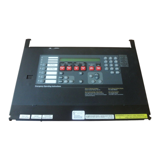
- Page 39 4100U/4100ES Panels 4100U/4100ES Panel The 4100U or 4100ES panel serves as the system controller for the Simplex Smoke Control FigureTag FD4-465- System. It controls the communications between the other system components within the smoke control system. This panel can be used in a dedicated or a non-dedicated smoke control application.
-
Page 40: 4190 Truesite Workstation And 24 Point I/O Graphic Interface
4190 TrueSite Workstation System and 24 Point I/O Graphic Interface 4190 TrueSite The 4190 TrueSite Workstation (TSW) provides a graphical user workstation within the Simplex Workstation (TSW) Smoke System. You can interact with the smoke control system by entering input through a keyboard, mouse, or touch-screen. -
Page 41: Optional And Peripheral System Components
Optional and Peripheral System Components Optional System The following components may also be used in the Simplex Smoke Control System: Components • Network Display Unit (NDU). • 4010 Fire Alarm Control Panel (FACP). • LCD Annunciator. Note The designated FSCS must initiate smoke control commands at the highest priority. -
Page 42: Peripheral Components
Optional and Peripheral System Components, Continued Peripheral In addition to the components previously described, a Simplex Smoke Control System also Components contains one or more of the following addressable or conventional components: • Smoke Detection Device • Duct Smoke Detection Relay •... -
Page 43: Firefighter Smoke Control Station
The figure below shows a view of a typical Firefighter’s Smoke Control Station (FSCS) used with Control Station the Simplex Smoke Control System. FSCS panels are custom designed for each building. See the (FSCS) “FSCS Ordering Information” section later in this chapter. -
Page 44: Firefighter Smoke Control Station (Fscs)
Firefighter Smoke Control Station, Continued Firefighter Smoke The smoke control panel must work completely in conjunction with the fire alarm control panel. Control Station This is because the FSCS is used by firefighters to activate and deactivate all smoke control (FSCS) sequences in the event that the fire spreads and for smoke cleanup operations. -
Page 45: Fscs Ordering Information
ON all indicators to allow for visual confirmation of failed indicator LEDs. Note: Refer to Chapter 4 for a list of Simplex Field Wiring Diagrams and Interconnection Diagrams that can assist you in installing the Simplex Smoke Control System. -
Page 46: About The Fire Alarm Control Panel
Firefighter Smoke Control Station, Continued About the Fire Alarm The Fire Alarm Control Panel connects to all of the smoke detectors, manual pull boxes, fire Control Panel alarms, etc. within the building. When one of the FACP sensors detects a problem, the FACP informs the smoke control panel which sensor is in alarm condition and what the alarm condition is. -
Page 47: Chapter 4 Installing The Smoke Control System
Please refer to the applicable installation documents for component installation instructions. These documents are shipped with the individual components. All wiring in the Simplex Smoke Control System must comply with the National Electric Code (NFPA 70), the National Fire Alarm Code (NFPA 72), the appropriate Simplex Field Wiring diagrams (refer to the “Field Wiring and Interconnection Diagrams”... -
Page 48: General Smoke Control Interconnections
General Smoke Control Interconnections Overview A Simplex Smoke Control System is usually part of a larger Simplex Fire Alarm System. The Simplex Smoke Control System ties into the building air handling equipment, either dedicated, non-dedicated, or both, to form the overall Smoke Management system for the building. - Page 49 General Smoke Control Interconnections, Continued UUKL Addressable The following table lists the UUKL addressable monitor/control devices for the 4100U or 4100ES Monitor/Control system. Devices for 4100U and 4100ES Table 4-1. UUKL Addressable Monitor/Control Device List for 4100U/4100ES ® Model Description IDNet™...
-
Page 50: Reference Information
General Smoke Control Interconnections, Continued Reference For wiring details on the devices shown in the following sections, refer to the following reference Information information shown below: • MAPNET II/IDNet Devices Field Wiring Diagram ......841-804 • 4020/4100 Graphic Annunciator Field Wiring Diagram ....841-802 •... -
Page 51: Four Story Building Smoke Control Example
The figure below shows an application diagram for a four-story building. This figure illustrates Building Smoke how the elements of the Smoke Control System are architecturally related, how they fit within the Control Example overall Simplex Fire Alarm System, and how they relate to the building air handling systems. Figure Legend Description FACP Fire Alarm Control Panel (e.g., Model 4100U as described in Chapter 3). -
Page 52: Dedicated Smoke Control System Wiring
The following sections illustrate some examples of dedicated fan and damper control. Dedicated Damper control is a basic function of the Simplex Smoke Control System. Interconnections to Damper Control motorized dampers are shown in Figures 4-2 and 4-3. - Page 53 IAMs and 6-Point I/O Modules, except that the 4100-7401 module is used for both control and feedback. This module communicates with the 4100U/4100ES Master over the RUI communications, and offers the added advantage that all I/O is supervised. The figure below shows dedicated motorized damper control using the 4100-7401 24-Point I/O: Figure 4-3.
-
Page 54: Dedicated Fan Control
Dedicated Smoke Control System Wiring, Continued Dedicated Like smoke dampers, fan control is a basic function of the Simplex Smoke Control System. Fan Control General principles for interconnection to a dedicated fan are shown in Figures 4-4 and 4-5. In a dedicated fan control application, the 4090-9118 Relay IAM is used to provide inputs to a fan to turn it ON and monitor the feedback from the controller. - Page 55 6-Point I/O Modules, except that the 4100-7401 module is used for both control and feedback. This module communicates with the 4100U/4100ES Master over the RUI communications, and offers the added advantage that all I/O is supervised. The figure below shows the equivalent interconnects for applications using a 24-Point I/O Module.
-
Page 56: Non-Dedicated Smoke Control System Wiring Diagrams
Non-Dedicated Damper control and overriding the HVAC control of the damper is a basic function of the Simplex Damper Control Smoke Control System. Interconnections for dampers are shown in Figures 4-6 through 4-9. -
Page 57: Non-Dedicated Damper Control
Feedback of the closure is accomplished using a 4090-9120 6-Point I/O Module to monitor the Damper Control closed position limit switch on the damper. The module also communicates with the Simplex FACP via IDNet. Wiring from the module to the control relay is unsupervised, so it must be mounted within three feet of the relay/damper in accordance with NFPA 72. - Page 58 Non-Dedicated Smoke Control System Wiring Diagrams, Continued Non-Dedicated The figure below shows non-dedicated motorized damper control using the 24-Point I/O Module. Damper Control Figure 4-7. Non-Dedicated Motorized Damper Control Using the 24-Point I/O Module 4-12...
-
Page 59: Non Dedicated Fan Control
Like smoke dampers, fan control and overriding the HVAC control is a basic function of the Fan Control Simplex Smoke Control System. General principles for interconnection to a non-dedicated fan are shown in Figures 4-8 and 4-9. In a non-dedicated fan control application, a 4090-9120 6-Point I/O Module is used to provide inputs to a fan controller for smoke control override and monitor the feedback from the controller. - Page 60 6-Point I/O Module, except that the 4100-7401 24-Point I/O Module is used for both control and feedback. This module communicates with the 4100U/4100ES Master over the RUI communications SLC, and offers the added advantage that all I/O is supervised, so no restrictions on module placement are required.
-
Page 61: Chapter 5 Smoke Control System Programs
Smoke Control System Programs Introduction This chapter provides examples of Simplex Smoke Control System programs. These programs are presented to illustrate what can be accomplished with this system. Since every system is unique, your programs will not be identical to these programs. Instead, use these programs as templates when programming the system. -
Page 62: Smoke Control Program Requirements
Smoke Control Program Requirements Introduction The following paragraphs describe the requirements for the various types of programs that can be implemented using the Simplex Smoke Control System. Emergency Emergency operation programs have the following functions: Operation • Zoned smoke control to activate from automatic devices only. -
Page 63: Dedicated Smoke Control System Weekly Self-Test
Dedicated Smoke Control System Weekly Self-Test Custom Control The Custom Control equations in this example are written for 4100U/4100ES based smoke control Programming system, and show how to implement the Dedicated Smoke Control System Weekly Self-Test Example requirement described on the previous page. -
Page 64: Equation 3: Test Stairwell Air Pressure
Dedicated Smoke Control System Weekly Self-Test, Continued Label: TEST STAIRWELL AIR PRESSURE Equation 3 Equation 3: Test Stairwell Air Pressure COMMENTS: INPUTS: The ON state of: P281 UTILITY START SELF TEST PROGRAM AND the ON state of: M1-9 CPRESS STAIR PRESS FAN DELAY for 10 secs, running timer is A283 AND NOT the ON state of: M1-42... -
Page 65: Smoke Control System Custom Control Equations
Smoke Control System Custom Control Equations Introduction The following Custom Control (CC) equations are written for a 4100U/4100ES based smoke control system. Note that the points mentioned are representative of any system. Your system will use different points to provide the Inputs and Outputs. - Page 66 Smoke Control System Custom Control Equations, Continued Equation No. Label Smoke Control ------------------- ------------------------------------------------------------------- System CC Equation Summary REPORT TBL IF EXH DAMPER 3 NOT CLOSED REPORT TBL IF EXH DAMPER 4 NOT OPEN REPORT TBL IF EXH DAMPER 4 NOT CLOSED MANUAL CONTROL SUP AIR DAMPER 1 OPEN MANUAL CONTROL SUP AIR DAMPER 1 CLOSE MANUAL CONTROL SUP AIR DAMPER 2 OPEN...
-
Page 67: Equation 1: Set Up Normal Conditions At Startup
Smoke Control System Custom Control Equations, Continued Label: SET UP NORMAL CONDITIONS AT STARTUP Equation 1 Equation 1: Set Up Normal Conditions at COMMENTS: Startup INPUTS: The ON state of: TIMER SYSTEM STARTUP PULSE TIMER OUTPUTS: HOLD points ON pri=9,9 M1-10 CPRESS SUPPLY FAN RELAY... -
Page 68: Equation 3: Set Normal Conditions At Reset
Smoke Control System Custom Control Equations, Continued Label: SET NORMAL CONDITIONS AT RESET Equation 3 Equation 3: Set Normal Conditions at Reset COMMENTS: INPUTS: The ON state of: TIMER SYSTEM RESET PULSE TIMER OUTPUTS: HOLD points ON pri=9,9 P290 UTILITY SET NORMAL CONDITIONS AT RESET END: Label: SET NORMAL CONDITIONS AT RESET... -
Page 69: Equation 5: Initialize Normal Conditions At Reset
Smoke Control System Custom Control Equations, Continued Label: INITIALIZE NORMAL CONDITIONS AT RESET Equation 5 Equation 5: Initialize Normal Conditions at Reset COMMENTS: INPUTS: The ON state of: P290 UTILITY SET NORMAL CONDITIONS AT RESET AND NOT the TROUBLE state of: P256 TROUBLE FSCS SWITCHES NOT RESET... -
Page 70: Equation 7: Smoke Control Initiate
Smoke Control System Custom Control Equations, Continued Label: SMOKE CONTROL INITIATE Equation 7 Equation 7: Smoke Control Initiate COMMENTS: INPUTS: The ON state of: ANALOG NUMBER OF SYSTEM FIRE ALARMS OUTPUTS: TRACK points ON pri=9,9 P275 UTILITY SMOKE CONTROL ALARM INITIATE PULSE analog: A280, for 2 sec. -
Page 71: Equation 10: Activate Smoke Control Zone 1
Smoke Control System Custom Control Equations, Continued Label: ACTIVATE SMOKE CONTROL ZONE 1 Equation 10 Equation 10: Activate Smoke Control Zone 1 COMMENTS: The 5 second delay allows points that may be ON in test to be turned OFF prior to being turned ON by this smoke control equation. INPUTS: The ON state of: P276... -
Page 72: Equation 12: Activate Smoke Control Zone 2
Smoke Control System Custom Control Equations, Continued Label: ACTIVATE SMOKE CONTROL ZONE 2 Equation 12 Equation 12: Activate Smoke Control Zone 2 COMMENTS: INPUTS: The ON state of: P277 UTILITY SMOKE CONTROL ZONE 2 INITIATE DELAY for 5 sec., running timer is A285 OUTPUTS: HOLD points OFF pri=8,9 M1-14... -
Page 73: Equation 14: Activate Smoke Control Zone 3
Smoke Control System Custom Control Equations, Continued Label: ACTIVATE SMOKE CONTROL ZONE 3 Equation 14 Equation 14: Activate Smoke Control Zone 3 COMMENTS: INPUTS: The ON state of: P278 UTILITY SMOKE CONTROL ZONE 3 INITIATE DELAY for 5 sec., running timer is A286 OUTPUTS: HOLD points OFF pri=8,9 M1-14... -
Page 74: Equation 16: Activate Smoke Control Zone 4
Smoke Control System Custom Control Equations, Continued Label: ACTIVATE SMOKE CONTROL ZONE 4 Equation 16 Equation 16: Activate Smoke Control Zone 4 COMMENTS: INPUTS: The ON state of: P279 UTILITY SMOKE CONTROL ZONE 4 INITIATE DELAY for 5 sec., running timer is A287 OUTPUTS: HOLD points OFF pri=8,9 M1-14... -
Page 75: Equation 19: Report Tbl If Supply Fan Not On
Smoke Control System Custom Control Equations, Continued Label: REPORT TBL IF SUPPLY FAN NOT ON Equation 19 Equation 19: Report TBL if COMMENTS: Supply Fan Not ON INPUTS: The ON state of: M1-10 CPRESS SUPPLY FAN RELAY DELAY for 10 sec., running timer is A264 AND NOT the ON state of: M1-41 UTILITY... -
Page 76: Equation 23: Report Tbl If Stair Press Fan Not On
Smoke Control System Custom Control Equations, Continued Label: REPORT TBL IF STAIR PRESS FAN NOT ON Equation 23 Equation 23: Report TBL if Stair COMMENTS: Press Fan Not ON INPUTS: The ON state of: M1-9 CPRESS STAIR PRESS FAN DELAY for 10 sec., running timer is A265 AND NOT the ON state of: M1-42 UTILITY... -
Page 77: Equation 27: Report Tbl If Main Sup Damper Not Open
Smoke Control System Custom Control Equations, Continued Label: REPORT TBL IF MAIN SUP DAMPER NOT OPEN Equation 27 Equation 27: Report TBL if COMMENTS: Main SUP Damper INPUTS: Not Open The ON state of: M1-12 CDAMPER MAIN OUTSIDE AIR DAMPER DELAY for 10 sec., running timer is A266 AND NOT the ON state of: M1-48... -
Page 78: Equation 31: Report Tbl If Sup Damper 1 Not Open
Smoke Control System Custom Control Equations, Continued Label: REPORT TBL IF SUP DAMPER 1 NOT OPEN Equation 31 Equation 31: Report TBL If SUP COMMENTS: Damper 1 Not Open INPUTS: The ON state of: M1-15 CDAMPER 1ST FLOOR SUPPLY AIR DAMPER DELAY for 10 sec., running timer is A257 AND NOT the ON state of: M1-25... -
Page 79: Equation 35: Report Tbl If Sup Damper 3 Not Open
Smoke Control System Custom Control Equations, Continued Label: REPORT TBL IF SUP DAMPER 3 NOT OPEN Equation 35 Equation 35: Report TBL If SUP COMMENTS: Damper 3 Not Open INPUTS: The ON state of: M1-17 CDAMPER 3RD FLOOR SUPPLY AIR DAMPER DELAY for 10 sec., running timer is A272 AND NOT the ON state of: M1-27... -
Page 80: Equation 39: Report Tbl If Exh Damper 1 Not Open
Smoke Control System Custom Control Equations, Continued Label: REPORT TBL IF EXH DAMPER 1 NOT OPEN Equation 39 Equation 39: Report TBL if EXH COMMENTS: Damper 1 Not Open INPUTS: The ON state of: M1-19 CDAMPER 1ST FLOOR EXHAUST/RETURN AIR DAMPER DELAY for 10 sec., running timer is A258 AND NOT the ON state of: M1-33... -
Page 81: Equation 43: Report Tbl If Exh Damper 3 Not Open
Smoke Control System Custom Control Equations, Continued Label: REPORT TBL IF EXH DAMPER 3 NOT OPEN Equation 43 Equation 43: Report TBL If EXH COMMENTS: Damper 3 Not Open INPUTS: The ON state of: M1-21 CDAMPER 3RD FLOOR EXHAUST/RETURN AIR DAMPER DELAY for 10 sec., running timer is A278 AND NOT the ON state of: M1-35... -
Page 82: Equation 47: Manual Control Sup Air Damper 1 Open
Smoke Control System Custom Control Equations, Continued Label: MANUAL CONTROL SUP AIR DAMPER 1 OPEN Equation 47 Equation 47: Manual Control SUP AIR Damper 1 Open COMMENTS: INPUTS: The UP state of: 8-66 SWITCH Ann 1 Pt 66 Graphic LED/SW Ctlr w/32 AND the ON state of: P273 UTILITY... -
Page 83: Equation 51: Manual Control Sup Air Damper 3 Open
Smoke Control System Custom Control Equations, Continued Label: MANUAL CONTROL SUP AIR DAMPER 3 OPEN Equation 51 Equation 51: Manual Control SUP Air Damper 3 Open COMMENTS: INPUTS: The UP state of: 8-70 SWITCH Ann 1 Pt 70 Graphic LED/SW Ctlr w/32 AND the ON state of: P273 UTILITY... -
Page 84: Equation 55: Manual Control Exh Air Damper 1 Open
Smoke Control System Custom Control Equations, Continued Label: MANUAL CONTROL EXH AIR DAMPER 1 OPEN Equation 55 Equation 55: Manual Control EXH Air Damper 1 Open COMMENTS: INPUTS: The UP state of: 8-67 SWITCH Ann 1 Pt 67 Graphic LED/SW Ctlr w/32 AND the ON state of: P273 UTILITY... -
Page 85: Equation 59: Control Exh Air Damper 3 Open
Smoke Control System Custom Control Equations, Continued Label: MANUAL CONTROL EXH AIR DAMPER 3 OPEN Equation 59 Equation 59: Control EXH Air Damper 3 Open COMMENTS: INPUTS: The UP state of: 8-71 SWITCH Ann 1 Pt 71 Graphic LED/SW Ctlr w/32 AND the ON state of: P273 UTILITY... -
Page 86: Equation 63: Manual Control Stair Press Fan On
Smoke Control System Custom Control Equations, Continued Label: MANUAL CONTROL STAIR PRESS FAN ON Equation 63 Equation 63: Manual Control Stair Press Fan ON COMMENTS: INPUTS: The UP state of: 8-65 SWITCH Ann 1 Pt 65 Graphic LED/SW Ctlr w/32 AND the ON state of: P273 UTILITY... -
Page 87: Equation 67: Manual Control Main Ret Air Damper Open
Smoke Control System Custom Control Equations, Continued Label: MANUAL CONTROL MAIN RET AIR DAMPER OPEN Equation 67 Equation 67: Manual Control Main RET Air COMMENTS: Damper Open INPUTS: The UP state of: 8-75 SWITCH Ann 1 Pt 75 Graphic LED/SW Ctlr w/32 AND the ON state of: P273 UTILITY... -
Page 88: Equation 71: Manual Control Main Sup Air Damper Open
Smoke Control System Custom Control Equations, Continued Label: MANUAL CONTROL MAIN SUP AIR DAMPER OPEN Equation 71 Equation 71: Manual Control Main SUP Air COMMENTS: Damper Open INPUTS: The UP state of: 8-77 SWITCH Ann 1 Pt 77 Graphic LED/SW Ctlr w/32 AND the ON state of: P273 UTILITY... -
Page 89: Equation 75: Manual Control Clear Faults
Smoke Control System Custom Control Equations, Continued Label: MANUAL CONTROL CLEAR FAULTS Equation 75 Equation 75: Manual Control Clear Faults COMMENTS: INPUTS: The UP state of: 8-80 SWITCH Ann 1 Pt 80 Graphic LED/SW Ctlr w/32 AND the ON state of: P273 UTILITY MASTER KEY SWITCH ENABLE... -
Page 90: Equation 77: Turn Sonalert On
Smoke Control System Custom Control Equations, Continued Label: TURN SONALERT ON Equation 77 Equation 77: Turn SONALERT ON COMMENTS: INPUTS: OR the ON state of: P260 UTILITY FL1 SUPPLY AIR DAMPER FAIL P261 UTILITY FL2 SUPPLY AIR DAMPER FAIL P262 UTILITY FL3 SUPPLY AIR DAMPER FAIL P263... -
Page 91: Chapter 6 Glossary Of Terms
Chapter 6 Glossary of Terms Introduction This chapter contains a glossary to terms that are used in this publication In this Chapter Refer to the page number listed in this table for information on a specific topic. Topic See Page # Glossary of Terms... -
Page 92: Glossary
Glossary of Terms Glossary Acceptance Tests – Tests designed to prove a smoke control system is capable of doing what is designed to do. AHJ – The “Authority Having Jurisdiction” is the organization, office, or individual responsible for approving equipment, an installation, or a procedure. Alarm Service –... - Page 93 Glossary of Terms, Continued Glossary Bypass Pressure Control System – The bypass-around supply fan can actually be placed at any level. The bypass duct dampers are controlled by one or more static pressure sensors located between the stairtower and the building. In addition, a manually operated damper may be located at the top of the stairtower for smoke purging by the Fire Department.
- Page 94 Glossary of Terms, Continued Glossary Control Unit – A device with the control circuits necessary to (a) furnish power to a fire alarm system; (b) receive signals from alarm initiating devices and transmit them to audible alarm notification appliances and accessory equipment; and (c) electrically supervise the system installation wiring and primary (main) power.
- Page 95 Glossary of Terms, Continued Glossary Ground Fault – A condition in which the resistance between a conductor and ground reaches an unacceptably low level. Heat Detector – A device which detects abnormally high temperature or rate-of-temperature rise. Horns – An audible signal appliance in which energy produces a sound by imparting motion to a flexible component that vibrates at some nominal frequency.
- Page 96 Glossary of Terms, Continued Master Box – A municipal fire alarm box that may also be operated by remote means. Glossary Multiplexing – A signaling method characterized by the simultaneous or sequential transmission, or both, and reception of multiple signals in a communication channel including means for positively identifying each signal.
- Page 97 Glossary of Terms, Continued Glossary Proprietary Protective Signaling System – An installation of protective signaling systems that serve contiguous and noncontiguous properties under one ownership from a central supervising station located at the protected property, where trained, competent personnel are in constant attendance.
- Page 98 TSW – TrueSite Workstation System. The 4190 TSW provides a graphical user workstation within the Simplex Smoke System. Visible Signal – A visible signal is the response to the operation of an initiating device by one or more direct or indirect visible notification appliances.
-
Page 99: Index
Index 24-Point I/O Graphic Interface, 3-4 elevator shafts, 1-18 Emergency Operation, 5-2 end-range switches, 1-20 Equation 1 4010 Fire Alarm Control Panel (FACP), 3-5 Start Self Test, 5-3 4020 FACP, 3-5 Equation 2 4190 TrueSite Workstation, 3-4 Turn ON Stair Pressure Fan, 5-3 Equation 3 Test Stairwell Air Pressure, 5-4 Equation 4... - Page 100 manual control panel, 1-19 smoke control interconnections, 4-2 manual fire alarm pull boxes, 2-4 Smoke Control Program Requirements, 5-2 manual pull boxes, 1-9 smoke control system, 1-9 manual pull stations, 1-19 Smoke Control System Custom Control manually-operated damper, 1-17 Equations, 5-5 master key-switch, 3-8 smoke control systems, 1-1 monitored switches, 2-3...
- Page 102 574-465 Rev. D ©2005-2010 SimplexGrinnell LP. Specifications and other information were current as of publication and are subject to change without notice.
Need help?
Do you have a question about the 4100U and is the answer not in the manual?
Questions and answers